The principles here apply equally to 2 single coil pickups (such as a Telecaster, 2-pickup Stratocaster, or P90 Les Paul), 2 humbucking pickups (such as a Les Paul), or the two coils of a 4 conductor humbucker pickup (such as a Gibson Burstbucker, Seymour Duncan JB, Seymour Duncan Red Devil, Seymour Duncan Hot Rails, or Seymour Duncan Hot Stack Strat). The possibilities will be severely limited when using active pickups, however, as the output from those has already been buffered. Active circuits may interfere with attempts to combine the pickups, or may require a shared ground. Active pickups are therefore not covered here, and this page is dedicated only to passive pickups.
Pickups are presented as having opposite polarity (North facing and South facing). For convention reasons, these are shown with the input and output (marked with a +) ends reversed, but in reality, the inputs and outputs are usually beside each other, with only the coils wound in opposing directions. The same principles will work even if the pickups have the same polarity, with the exception that humbucking will only apply to out-of-phase wirings, instead of in-phase.
Note that it is also possible for single pickups to have a coil tap (not a coil split), which allows the pickup to be used with a lower number of wire turns, reducing the power output, and making the pickup produce more high tones and harmonics. In such a case, each of the normal combinations is possible with one or both of the pickups being tapped to its reduced number of turns. That is covered in detail further down this page.
Configuration
Single pickup (or single coil)
Two pickups in series
Two pickups in parallel
In phase
Single pickup (or coil)
Tuned tap (fat tap)
Humbucker series
Humbucker parallel
Wiring
Ground to input of pickup 1. Output of pickup 1 to guitar output. Both ends of pickup 2 optionally grounded.
Ground to input of pickup 2. Output of pickup 2 to guitar output. Both ends of pickup 1 optionally grounded.
Ground to input of pickup 2. Output of pickup 2 to input of pickup 1. Output of pickup 1 to guitar output. Output of pickup 2 connected to ground through a capacitor.
Ground to input of pickup 1. Output of pickup 1 to input of pickup 2. Output of pickup 2 to guitar output. Output of pickup 1 connected to ground through a capacitor.
Ground to input of pickup 1. Output of pickup 1 to input of pickup 2. Output of pickup 2 to guitar output.
Ground to inputs of pickups 1 and 2. Outputs of pickups 1 and 2 to guitar output.
Usage for two separate pickups
Standard single pickup selection.
Not normally used, since it can be replicated with separate tone controls.
Not normally used, but can be used to make a pair of single coil pickups give high output similar to a humbucker, or a pair of humbucking pickups give very high output.
Standard arrangement for combining pickups.
Usage for two humbucker coils
Standard single coil arrangement for split coil humbuckers. Allows a humbucker pickup to function and sound more like a Stratocaster pickup.
Gibson's emulation of P90 pickups.
Standard humbucking pickup arrangement for most high output guitars (PAF, Patent Sticker, Filtertron, Fidelitron, typical humbucker, typical stacked pickup, typical sidewinder pickup).
Provides a humbucking single coil sound, available with some Ibanez Tri-sound switching configurations.
Sound (comparative)
Bright (more harmonics and high tones) and crisp.
Fat sound (lots of low tones), with lots of power.
Fat sound (lots of low tones) with more mid/high and harmonics than a P90, and with lots of power.
Similar to a single pickup positioned half way between the two pickups.
Output power
Medium
High
High
Medium
Output pickup differences
Pickup close to the bridge sounds bright (more harmonics and high tones). Pickup close to the neck sounds darker (dominated by lower tones). Pickups sound almost identical when positioned close to each other, far from the bridge.
Almost no difference because pickups are so close to each other. Slightly more high tones when the output pickup is closer to the bridge. Much more noticeable if the pickups have different tonal outputs.
None
None
Humbucking with same polarity
No
No
No
No
Humbucking with opposite polarity (as shown)
No
Yes, low tones only
Yes
Yes
Notes
Unused pickup may be optionally grounded at both ends.
Out of phase
Tuned tap out of phase
Series out of phase
Parallel out of phase
Wiring
Ground to output of pickup 2. Input of pickup 2 to input of pickup 1. Output of pickup 1 to guitar output. Input of pickup 2 connected to ground through a capacitor.
Ground to output of pickup 1. Input of pickup 1 to input of pickup 2. Output of pickup 2 to guitar output. Input of pickup 1 connected to ground through a capacitor.
Ground to input of pickup 1. Output of pickup 1 to output of pickup 2. Input of pickup 2 to guitar output.
Ground to input of pickup 1 and output of pickup 2. Output of pickup 1 and input of pickup 2 to guitar output.
Usage for two separate pickups
Not normally used, since it can be replicated with separate tone controls.
Higher power out of phase arrangement.
Standard out of phase arrangement.
Usage for two humbucker coils
Unusual out of phase arrangement.
Not normally used, since it produces relatively little output, but available with some Ibanez Tri-sound switching configurations.
Not normally used, since it produces very little output.
Sound (comparative)
Dominated by mids, similar to a wah-wah pedal in middle position.
Higher output version of parallel output, but with fewer harmonics. With separate pickups, end result can sound similar to in-phase parallel wiring, but with slightly less low tones. Turning down a tone dial (with separate pickups) causes mids to become dominant.
Thin version of normal pickup sound, dominated by harmonics, similar to a wah-wah pedal in high-pass position. Turning down a tone dial (with separate pickups) causes mids to increase.
Output power
Medium
Medium for separate pickups, low for two humbucker coils
Low
Output pickup differences
Almost no difference because pickups are so close to each other. Slightly more high tones when the output pickup is closer to the bridge. Much more noticeable if the pickups have different tonal outputs.
None
N/A
Humbucking with same polarity
Yes, low tones only
Yes
Yes
Humbucking with opposite polarity (as shown)
No
No
No
Notes
Basically sounds like the difference between the pickups. Pickups placed further apart or with other differences will produce a higher output.
Half out of phase
Half out of phase
Wiring
Ground to input of pickup 1 and output of pickup 2. Output of pickup 1 to guitar output. Input of pickup 2 connected to guitar output through a capacitor.
Ground to input of pickup 2 and output of pickup 1. Output of pickup 2 to guitar output. Input of pickup 1 connected to guitar output through a capacitor. (Sometimes done simply by using the same circuit as the first version, but taking the output from the input of pickup 2. However, this leaves the low notes out of phase with any other pickups.)
Usage for two separate pickups
Common modification to allow Telecasters to produce a similar sound to a Stratocaster with two pickups enabled.
Usage for two humbucker coils
Unusual arrangement.
Sound (comparative)
Hollowed out, with mids cut.
Output power
Medium
Output pickup differences
More low tones when the output pickup is closer to the neck.
Humbucking with same polarity
Yes, high tones only
Humbucking with opposite polarity (as shown)
No
Notes
More powerful than normal out of phase, as bass tones are not cut.
The following circuit covers all 12 possibilities for a humbucker. It uses one rotary switch to select the coil arrangement, then uses a switch (such as a push/pull switch in one of the volume controls) to switch it to out-of-phase. I refer to this overall arrangement as the Rotary Weaver, since it is a highly organised bird's nest, like that of a weaver bird. On a guitar with two humbuckers, there will be two copies of this circuit, one for each humbucker. Humbucker pickups designed to sound like a traditional humbucker will generally work better, since humbucker pickups designed to sound like a traditional single coil pickup may become far too bright when split.
Wiring for all 12 options (suggested switching circuit for a humbucker pickup): Neck-most pickup input to rotary pole 2. Neck-most pickup output to rotary pole 1. Bridge-most pickup input to rotary pole 4. Bridge-most pickup output to rotary pole 3. Push/pull in pushed position pole 1 output and pulled position pole 2 output to rotary pole 5. Push/pull in pushed position pole 2 output and pulled position pole 1 output to rotary pole 6. Hot output (to guitar) to rotary pole 1 outputs 1, 2 and 5, rotary pole 4 outputs 3 and 6, and rotary pole 5 outputs 4 and 5. Floating ground output (to guitar) to rotary pole 1 output 6, rotary pole 2 outputs 1, 4 and 5, rotary pole 3 output 6, rotary pole 4 output 1, and rotary pole 6 outputs 2, 3 and 5. Push/pull pole 1 to rotary pole 1 output 3 and rotary pole 4 outputs 2, 4 and 5. Push/pull pole 2 to rotary pole 2 outputs 3 and 6, and rotary pole 3 outputs 1, 2, 4 and 5. Rotary pole 1 output 4 to rotary pole 6 output 4. Rotary pole 2 output 2 to rotary pole 3 output 3, rotary pole 5 outputs 2 and 3, and via tuned tap capacitor to floating ground output. Rotary pole 5 output 1 to Rotary pole 5 output 6 and via half-out-of-phase capacitor to hot output.
Push/pull
Rotary position 1
Rotary position 2
Rotary position 3
Rotary position 4
Rotary position 5
Rotary position 6
Down (off) = in phase
Neck-most single coil
Tuned tap (P90 emulation) with neck-most coil priority
Tuned tap (P90 emulation) with bridge-most coil priority
Humbucker series
Humbucker parallel
Bridge-most single coil
Up (on) = out of phase
Neck-most coil with bridge-most coil half out of phase
Tuned tap (P90 emulation) with neck-most coil priority and bridge-most coil out of phase
Tuned tap (P90 emulation) with bridge-most coil priority and neck-most coil out of phase
Humbucker series out of phase
Humbucker parallel out of phase
Bridge-most coil with neck-most coil half out of phase
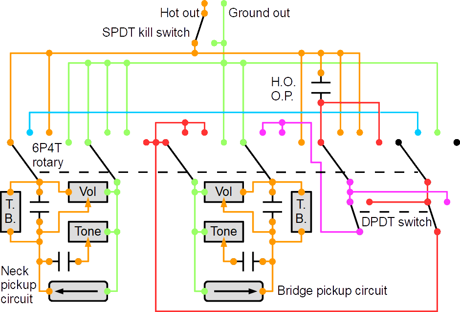
The same approach is then used to switch between pickups on the guitar, using a total of 7 controls (including separate volume and tone controls), with 3 push/pull switches. There is not much point in having tuned tap for the master pickup selection, since the same effect can be achieved by using series wiring, and turning down a tone dial. Therefore positions 2 and 3 on the rotary switch can be omitted for master selection, as well as the tuned tap capacitor. This gives 12 positions for each humbucking pickup, and 8 for the master controls, giving a staggering 1152 configurations with just 2 humbuckers. For master controls, wire volume and tone controls so that they use the pickup's "floating ground out" wire instead of the guitar's ground, so that they can modify each pickup separately even in series.
Wiring for 8 master options (suggested switching circuit for master switching): Using tone controls and decoupled volume controls with treble bleed circuit for each pickup.
Neck pickup switching circuit's floating ground output to rotary pole 2.
Anticlockwise pin of neck volume control to rotary pole 2.
Anticlockwise pin of neck tone control to rotary pole 2.
Neck pickup switching circuit's hot output to centre pin of neck volume control. Clockwise pin of neck volume control to rotary pole 1.
Clockwise pin of neck volume control via neck treble bleed capacitor to centre pin of neck volume control. Clockwise pin of neck volume control via neck treble bleed resistor to centre pin of neck volume control.
Centre pin of neck tone control via neck tone capacitor to neck pickup switching circuit's hot output.
Bridge pickup switching circuit's floating ground output to rotary pole 3.
Anticlockwise pin of bridge volume control to rotary pole 3.
Anticlockwise pin of bridge tone control to rotary pole 3.
Bridge pickup switching circuit's hot output to centre pin of bridge volume control. Clockwise pin of bridge volume control to rotary pole 4.
Clockwise pin of bridge volume control via bridge treble bleed capacitor to centre pin of bridge volume control. Clockwise pin of bridge volume control via bridge treble bleed resistor to centre pin of bridge volume control.
Centre pin of bridge tone control via bridge tone capacitor to bridge pickup switching circuit's hot output.
Push/pull in pushed position pole 1 output and pulled position pole 2 output to rotary pole 5. Push/pull in pushed position pole 2 output and pulled position pole 1 output to rotary pole 6. Hot output (to amplifier) to SPDT kill switch pole. Kill switch pushed/default output to rotary pole 1 outputs 1 and 3, rotary pole 4 output 4, and rotary pole 5 outputs 2 and 3. Kill switch pulled/alternate output to floating ground output. Floating ground output (to guitar) to rotary pole 1 output 4, rotary pole 2 outputs 1, 2 and 3, rotary pole 3 output 4, rotary pole 4 output 1, and rotary pole 6 output 3. Push/pull pole 1 to rotary pole 4 outputs 2 and 3. Push/pull pole 2 to rotary pole 2 output 4, and rotary pole 3 outputs 1, 2 and 3. Rotary pole 1 output 2 to rotary pole 6 output 2. Rotary pole 5 output 1 to Rotary pole 5 output 4 and via half-out-of-phase capacitor to kill switch pushed/default output.
Push/pull
Rotary position 1
Rotary position 2
Rotary position 3
Rotary position 4
Down (off) = in phase
Neck pickup
Pickups in series
Pickups in parallel
Bridge pickup
Up (on) = out of phase
Neck pickup with bridge pickup half out of phase
Pickups in series out of phase
Pickups in parallel out of phase
Bridge pickup with neck pickup half out of phase
The suggested circuit does cause the volume and tone to be wired backwards (to the pickup's new input instead of its output) whenever a pickup is out of phase, but they should still function correctly. (In most guitars with out of phase and separate controls, the phase switching is done directly to the pickup's input and output wires. However, this then forces only one of the pickups to be switched out of phase. Some of the options provided by this circuit require both pickups to be able to operate out of phase, so the usual approach would not be possible. And besides, it should work anyway, so there is no need to worry.)
4P6T and 6P6T, the shortest ones you can find - thicker ones need a thicker bodied guitar - C4D0606N-A and C4D0604N-A require 3.5 cm (just under 1⅜ inches) and turn a full circle, 09A30-02-3-04N-F also requires 3.5 cm while turning a partial circle, Grayhill 71B30-03-2-06N requires 3.2 cm (1¼ inches) while turning a partial circle, and 44M30-03-2-065 requires 4.5 cm (1¾ inches) while turning a partial circle, but some are available as a rotary base and separate decks to add as many poles as you need
Because of the amount of wiring, it is essential to use shielded wires wherever possible (connected to the guitar's ground), and ensure that control cavities are also shielded using a conductive coating. The cases of the potentiometers should be grounded using the guitar's ground for shielding. Note, however, that since the tone and volume controls are wired to the pickup switching circuit's floating ground, the ground pin of each potentiometer must not be connected to the case of the potentiometer.
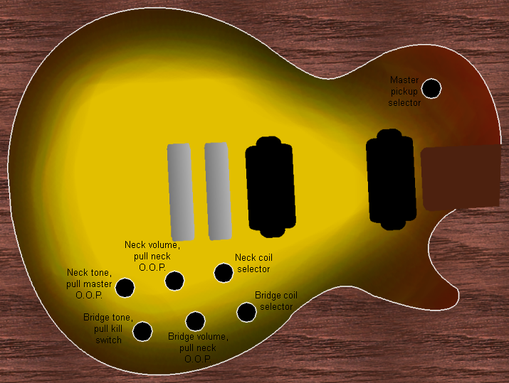
Suggested control layout on an LP style guitar: Master pickup selector in the usual selector switch position. 6 controls in 2 rows in the usual position of the volume and tone controls. Top row (when the guitar is held horizontally); neck coil selector, neck volume, neck tone. Bottom row; bridge coil selector, bridge volume, bridge tone. Pull neck volume to set neck coil to out of phase. Pull bridge volume to set bridge coil to out of phase. Pull neck tone to set master out of phase. Pull bridge tone as a kill switch.
Alternatively, if the guitar has enough space between the bridge and bottom strap button (such as on an Explorer), the normally wasted space can be used for the controls instead, something which is commonly seen with an XY MIDIpad, for example. Four of the controls would be in the usual location for the four controls of an LP, with two aditional controls above them instead of beside them. In such a case the controls could be arranged with the neck controls closer to the neck, and the bridge controls further from the neck. This is rather more intuitive than the normal LP control layout.
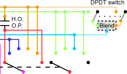
One missing option is the abilitity to blend in percentages between single coil and series humbucker. Fender offers this option in certain HH versions of their Jaguar guitar, and Peavey did the same on their T-60. This is also basically how Dan Armstrong's Stratocaster mod works when two pickup coils are in series (in parallel it just varies the volume of two pickups inversely to each other, something that can be done with the volume dials in a Rotary Weaver circuit).
The way this is done is quite ugly, as it is simply a variable resistor with one end connected to ground, and the other end connected to the wire that joins the coils of the humbucker in series. This resistor is always there, so it alters the impedance seen by both of the humbucker coils, and therefore alters the tone (a Fender TBX control produces its bass-cutting effect by altering this impedance). The resistor has random, unpredictable effects on the tone and volume controls, depending on what values are currently selected on all of them. It also causes the partially used coil to influence the tonal output of the not-quite-single coil all the way until it has reached 0, since it is still adding to the impedance. The effect it has influences the treble much more than the bass, so when it is partially turned down, it reduces the treble on both coils much faster than the bass, and the output sounds much more muddy than it should (this is sometimes used intentionally as an alternative way to produce Gibson's tuned tap effect). As a result, I do not recommend using this modification.
However, if you would like to do it, simply connect the centre pin of a potentiometer (Fender use a 1 MΩ linear potentiometer for one of them, and a 50 KΩ linear potentiometer for the other one, while Peavey used a 500 KΩ linear potentiometer) to pole 1 or 6 ouput 4 of the 6P6T rotary switch, and connect the anticlockwise potentiometer pin to the floating ground. This will only allow you to prioritise one of the two coils of the humbucker.
If you would also like to be able to do this with the other coil as well, connect the clockwise end of the potentiometer to the hot output; at each end of its travel only one coil will be active, while in the middle both will be active. This introduces a constant impedance in all settings, so keep it high enough that it doesn't alter the tone too much, such as 1 or 2 MΩ. It may help to get one with a centre detent and a linear response, so you can feel where the 50% setting is. For best results, it should be a DPDT push/pull potentiometer, with the switches connecting the ends of the potentiometer to the hot and floating ground, so that it is normally removed from the circuit so that it does not affect the impedance. For it to have an effect, you would need to pull the switch, so that it puts the potentiometer into the circuit, then turn the dial to the desired amount of blend. Blending would only happen when the humbucker coil selection is set to humbucker series (in-phase or out-of-phase).
Wiring for blend control, as part of the humbucker coil selection circuit: Push/pull in pulled position pole 1 output to hot output. Push/pull in pulled position pole 2 output to floating ground output. Push/pull pole 1 to anticlockwise pin of blend control. Push/pull pole 2 to clockwise pin of blend control. Rotary pole 6 (or 1) output 4 to centre pin of blend control.
This all seems totally unnecessary when you already have 1152 configurations to choose from. Do you really need more? If you really want to blend humbucker and single coil, you can already do it properly by setting one of the existing humbuckers to single coil, and keeping the other one as a humbucker, and blend them with the volume controls.
It is, of course, possible to use standard Gibson wiring for the tone and volume controls - swapping the centre and clockwise pin connections of the volume potentiometers - so that the two volume controls are coupled (turning one of them fully down causes the other pickup to go silent when the pickups are in parallel). The treble bleed circuits may be considered optional in such cases, depending on taste. It is also possible to use a Passive Treble/Bass tone circuit instead of a single tone control, which would allow bass tones to be cut as well as treble, but this will require an extra 2 potentiometers, and causes each bass tone control to affect both pickups when they are in series. (It is also possible to wire the ground of the tone and volume controls to the guitar's ground. However, this will cause one of them to act as a master volume and tone when the pickups are in series, and will produce some totally unpredictable behaviour in out of phase and half out of phase modes.) It would not be possible to use a TBX dial reliably, since they rely on the output of a pickup being static (they provide a variable impedance that acts as a load on the pickup, causing various frequencies to be cut), while the pickup's output here could change massively depending on which options are chosen for splitting or combining the coils.
The Rotary Weaver circuit builds on the concepts developed over many decades by countless luthiers, musicians, and electronics engineers. The switching circuit itself was developed by Tarquin Wilton-Jones on 15 November 2018, and publicly published on 5 December 2018. It was developed entirely independently, and was not based on any other published circuits.
Coil taps are often confused with coil splits, but they are not the same thing. (Note that Gibson's Tuned Tap - also known as Fat Tap - is neither a coil split nor a coil tap, but is perhaps closest to a coil split. It is decribed above.)
A coil split allows the two coils of a humbucker pickup to be accessed separately, so that they can be treated as two separate pickups, each with reduced power and a brighter sound than the humbucker arrangement. This typically results in a humbucker pickup with four conductors (optionally with an additional shielding wire); one for each end of the two coils. Technically there only needs to be 3 signal conductors (such as the Seymour Duncan Classic Stack Plus), with the output of the first coil permanently connected to the input of the second coil, but that prevents many applications (including a Rotary Weaver circuit), and it is not normal for pickups to be made that way.
A coil tap applies to a single pickup coil, and is therefore normally only found in single coil pickups. A single coil pickup may be made from a wire wrapped 8000-10000 times (turns) around the magnets. All single coil pickups have a single tap at the end of the wire; 100% of the turns. A tapped single coil pickup may provide two taps, one at the end of the wire (100%), and one after a fraction of the coils. For example, a P90 pickup normally has about 10000 turns of wire. A tapped P90 pickup may have one tap after 8000 turns (80%), and one after 10000 turns (100%). This would result in a pickup with three conductors, one for the pickup's input, one for the 80% tap, and one for the 100% tap. If the output is taken at the 100% tap, it will sound like a normal P90. If the output is taken at the 80% tap, it will have a lower power and brighter sounding output, more like a Stratocaster pickup.
By comparison, a humbucker may have between 10000 and 12000 turns in total. When split, each coil may have only 5000 turns, so they can be lower power or brighter sounding than a Stratocaster pickup. Some even have uneven numbers of windings, so that one coil might have 4500 turns, while the other might have 5500. (The overall power and tone is also affected by many other factors, such as the strength and arrangement of the magnets, wire guage, coil resistance, coil inductance, the transformer effect of the closely positioned coils, and how close the string is to the pickup. This is why a coil tapped P90 will not sound identical to a Stratocaster pickup, and why a Filtertron's large magnet gives a high output despite having far fewer coils than a PAF humbucher.)
Wiring configurations for single coil and humbucker pickups with coil split and tap. These figures show idealised pickups where the wires are wrapped from bottom to top, so that you can visualise how the taps relate to the number of turns. In real pickups, the conductors are likely to all come out beside each other at the bottom of the pickup, and the wires are wrapped randomly up and down the magnets.
Arrangement
Single coil
Humbucker
Basic
Wiring for a basic single coil pickup; green is input (typically ground), orange is hot/output. There may also be an optional shielding wire that grounds the pickup's chassis/cover and shields the conductors.
Wiring for a basic humbucker pickup; green is input (typically ground), blue connects the two pickup coils, orange is hot/output. There may also be an optional shielding wire that grounds the pickup's chassis/cover and shields the conductors.
Coil split
Wiring for a coil split humbucker pickup; green is input (typically ground), blue connects the two pickup coils, orange is hot/output, with a switch to select between humbucker and coil split. The switch is wired for the most basic split, where the output of the first coil is grounded, leaving only the second coil functioning. In most humbuckers that can be split, the output of the first coil and input of the second coil have two separate conductors, which can be joined to make a humbucker, connected to ground for a basic coil split, or connected in some other way to allow other possibilities (such as the Rotary Weaver).
Coil tap
Wiring for a coil tapped single coil pickup; green is input (typically ground), orange is the 100% hot/output tap, pink is the 80% hot/output tap, with a switch to select between the taps.
Wiring for a coil tapped humbucker pickup; green is input (typically ground), blue connects the two pickup coils, orange is the 100% hot/output tap for the second coil, pink is the 80% hot/output tap for the second coil, with a switch to select between the taps. This sort of pickup is technically possible, but extremely rare in reality. When someone says that a humbucker has been wired for "coil tap", they usually mean coil split.
Coil split and coil tap
Wiring for a coil split and coil tapped humbucker pickup; green is input (typically ground), blue is the 100% hot/output tap for the first coil, brown is the 60% hot/output tap for the first coil, the continuing blue then connects the two pickup coils, orange is the 100% hot/output tap for the second coil, pink is the 80% hot/output tap for the second coil, switch 1 selects between humbucker and coil split using the most basic split, switch 2 selects between the output taps on the first coil, and switch 3 selects between output taps on the second coil. This sort of pickup is technically possible, but extremely rare in reality. When someone says that a humbucker has been wired for "coil tap", they usually mean coil split.
The Rotary Weaver circuits do not cater to pickups with coil taps (rather than coil splits). An extra coil tap (in addition to the normal 100% tap) nearly doubles the number of options. If one coil is has 2 tap positions (eg. 100% and 75%), the 12 possibilities become 23 (11 * taps_for_coil + 1). If two coils each have 2 tap positions (eg. 100% and 75%), the 23 possibilities become 44. If two coils each have 3 tap positions (eg. 100%, 75% and 50%), there are 93 possibilities (10 * taps_for_first_coil * taps_for_second_coil + taps_for_first_coil + taps_for_second_coil). For this reason, a rotary switch quickly becomes unmanageable. Any coil taps should be implemented with a single toggle switch per tappable coil, selecting the tap position for that coil. So for the example twin humbucker guitar, if all four coils can be tapped, another four controls are needed, giving a total of 11 controls. With the suggested wiring, 2 humbuckers with 3 taps per coil would give 69192 total combinations. This way lies insanity! Fortunately, very few standard humbuckers are made with coil taps, even though it is technically possible for each of the humbucker's coils to have coil taps as well.
 Ground to input of pickup 1. Output of pickup 1 to guitar output. Both ends of pickup 2 optionally grounded.
 Ground to input of pickup 2. Output of pickup 2 to guitar output. Both ends of pickup 1 optionally grounded.
 Ground to input of pickup 2. Output of pickup 2 to input of pickup 1. Output of pickup 1 to guitar output. Output of pickup 2 connected to ground through a capacitor.
 Ground to input of pickup 1. Output of pickup 1 to input of pickup 2. Output of pickup 2 to guitar output. Output of pickup 1 connected to ground through a capacitor.
 Ground to input of pickup 1. Output of pickup 1 to input of pickup 2. Output of pickup 2 to guitar output.
 Ground to inputs of pickups 1 and 2. Outputs of pickups 1 and 2 to guitar output.
 Ground to output of pickup 2. Input of pickup 2 to input of pickup 1. Output of pickup 1 to guitar output. Input of pickup 2 connected to ground through a capacitor.
 Ground to output of pickup 1. Input of pickup 1 to input of pickup 2. Output of pickup 2 to guitar output. Input of pickup 1 connected to ground through a capacitor.
 Ground to input of pickup 1. Output of pickup 1 to output of pickup 2. Input of pickup 2 to guitar output.
 Ground to input of pickup 1 and output of pickup 2. Output of pickup 1 and input of pickup 2 to guitar output.
 Ground to input of pickup 1 and output of pickup 2. Output of pickup 1 to guitar output. Input of pickup 2 connected to guitar output through a capacitor.
 Ground to input of pickup 2 and output of pickup 1. Output of pickup 2 to guitar output. Input of pickup 1 connected to guitar output through a capacitor. (Sometimes done simply by using the same circuit as the first version, but taking the output from the input of pickup 2. However, this leaves the low notes out of phase with any other pickups.)
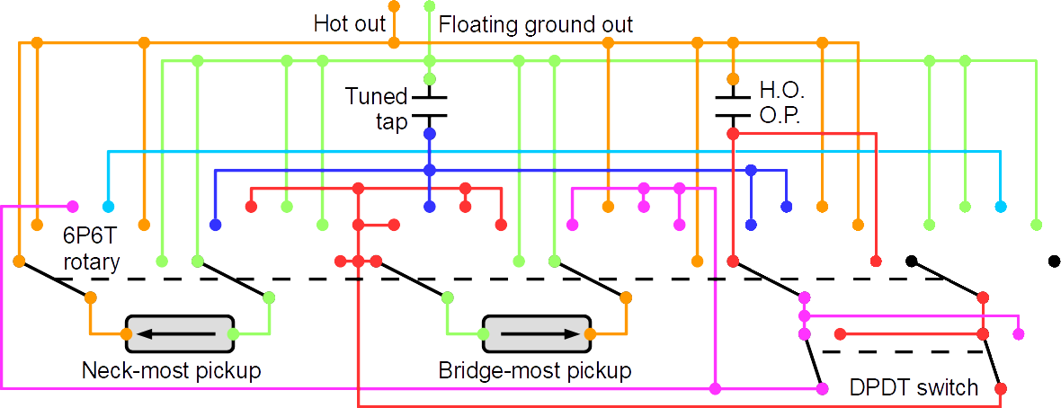
 Wiring for a basic single coil pickup; green is input (typically ground), orange is hot/output. There may also be an optional shielding wire that grounds the pickup's chassis/cover and shields the conductors.
 Wiring for a basic humbucker pickup; green is input (typically ground), blue connects the two pickup coils, orange is hot/output. There may also be an optional shielding wire that grounds the pickup's chassis/cover and shields the conductors.
 Wiring for a coil split humbucker pickup; green is input (typically ground), blue connects the two pickup coils, orange is hot/output, with a switch to select between humbucker and coil split. The switch is wired for the most basic split, where the output of the first coil is grounded, leaving only the second coil functioning. In most humbuckers that can be split, the output of the first coil and input of the second coil have two separate conductors, which can be joined to make a humbucker, connected to ground for a basic coil split, or connected in some other way to allow other possibilities (such as the Rotary Weaver).
 Wiring for a coil tapped single coil pickup; green is input (typically ground), orange is the 100% hot/output tap, pink is the 80% hot/output tap, with a switch to select between the taps.
 Wiring for a coil tapped humbucker pickup; green is input (typically ground), blue connects the two pickup coils, orange is the 100% hot/output tap for the second coil, pink is the 80% hot/output tap for the second coil, with a switch to select between the taps. This sort of pickup is technically possible, but extremely rare in reality. When someone says that a humbucker has been wired for "coil tap", they usually mean coil split.
 Wiring for a coil split and coil tapped humbucker pickup; green is input (typically ground), blue is the 100% hot/output tap for the first coil, brown is the 60% hot/output tap for the first coil, the continuing blue then connects the two pickup coils, orange is the 100% hot/output tap for the second coil, pink is the 80% hot/output tap for the second coil, switch 1 selects between humbucker and coil split using the most basic split, switch 2 selects between the output taps on the first coil, and switch 3 selects between output taps on the second coil. This sort of pickup is technically possible, but extremely rare in reality. When someone says that a humbucker has been wired for "coil tap", they usually mean coil split.