Surveys are a schematic rendering of the cave, using symbols to represent objects, not a photographic view. There are several types of survey that are used with caves. The most common is the plan view; this is a drawing of the cave as it would appear from above, like a standard map, so only the walls are visible, not the ceiling or floor. Each piece of the cave is drawn as if you were directly over that piece, without perspective.
The second type is a projected elevation; this is a view of the cave as it would appear when looking horizontally from one side. Each piece of the cave is drawn as if you were looking at it from that direction, without perspective, not from a static point. In general, only the ceiling and floor are visible, but some walls may be visible in passages that head directly away from the projected view. Passages can easily end up overlapping each other in horizontal systems. This approach allows the relationships between passages to be seen, and is generally the only approach that makes sense for viewing the elevation of highly complex caves.
The third type is an extended elevation; this takes all of the twists and turns of the passage, and unfolds them so that the passage can all be viewed from one side. Sometimes a fold may be intentionally added back, so that the passage may change direction from right to left, to help things fit on a page better, or to separate overlapping passages. Extended elevations break the relationships between passages, as loops might be longer on one side than on the other due to the number of twists in the passage, but they are the most common way to show vertical caves, such as rigging topos. Only the ceiling and floor are drawn, not the walls.
The fourth type of survey is a 3D rendering. This may be done from the perspective of looking at the cave from the outside, so that it can be rotated and tilted to get a better idea of the relationships between passages, or it may be done from the perspective of an internal view, as if you were walking through the cave.
Traditional cave surveys are prepared in a very simplistic manner. Firstly, a team surveys the cave using little more than a tape measure, compass, clinometer/inclinometer ("clino"), and notebook. They follow the passages, picking appropriate points along the passage, trying to remain in the centre of the passage where possible. Often the points will be on the ceiling or walls of a smaller passage. From each point (called a station), they take measurements of the compass bearing, inclination, and distance to the next point. To help see a distant station better, an assistant might hold a sighting card (a brightly coloured piece of plastic that is easier to aim for) on the station. Vertical drops are done with a plumbline instead of compass and clinometer, as both become fairly inaccurate at steep angles. These readings are written by hand onto a piece of paper, where each station is usually given a number instead of a name (though a name could be used for very important stations).
| From station | To station | Length | Compass | Clino |
|---|---|---|---|---|
| 1 | 2 | 7.53 | 117 | -7 |
| 2 | 3 | 3.24 | 76 | 15 |
| 3 | 4 | ... | ... | ... |
There will always be tiny errors when taking the readings, depending on how accurately the tools are used, and how well the tools are positioned on the stations. There will also be occasional mistakes when writing on the paper or reading the numbers from the paper afterwards. Mud and smudges can make things difficult to read, or a 15 could be mistaken for a 75. The numbers on the devices can be difficult to read, and it may be difficult to point them perfectly at the next station, especially when lying in awkward positions with your face stuck against a rock. The person taking the readings must have their head behind the devices, so when a leg points away from a wall where the station is, the devices cannot sit on the station; that person has to try to align their head and the devices perfectly in line between the two stations.
The combination of all of these lines is called a "centreline", even if it does not perfectly follow the centre of a passage, and even if it bounces off a wall or ceiling. The line between two stations is called a "leg". After correcting between magnetic and grid North, the data can then be plotted as a centreline, either laboriously by hand, or much faster, using a computer program, such as Survex. Any time a loop is completed, any legs along that loop must have their directions, inclinations, and lengths altered to compensate for any errors when closing the loop (where the two ends of the loop do not match up exactly). Survex is the most popular cave surveying program in the UK for doing this automatically, and several other applications embed Survex to do this job for them. Its rendering application Aven remains one of the most useful tools for visualising centreline data in 3D.
When talking about the length or depth of a cave, it is the length of the centreline that is used to decide the length. Sometimes it might be in a straight line while the passage gently wiggles, so it will be a little bit too short. Sometimes it might zig-zag from one wall to the other and be a bit too long. Overall, these differences are likely to average out, so it is treated as being the length of the cave. The highest and lowest stations normally give the depth (though sometimes the highest ceiling and lowest dip in the floor below the centreline might be used instead). When a passage gets two lines down it at the same time, one of them is ignored ("duplicate") during the calculation. Sometimes this is used to measure large chambers, and sometimes it is done because a branch needs to be surveyed from the nearest known survey station, which was part way back down the first passage.
For better passage dimension drawings, several more measurements are taken on the way. Firstly, at every station along the way, the distance to each wall, and the "normal" floor and ceiling are measured. In big passages, the height to the ceiling may either be estimated, or calculated using two angled spotlights, and trigonometry. The passage dimensions are usually measured at the station the leg starts from. If a leg is measured backwards (so the compass and clinometer are used from the wrong end of the leg), the "from" and "to" stations get written in the opposite order, but the passage measurements are done from the earlier station (so the "to" station) as if the leg were measured in the normal direction; this can be confusing for anyone who is not used to it, but it is important to make sure that every station gets the measurements.
| From | To | Length | Compass | Clino | Left | Right | Up | Down |
|---|---|---|---|---|---|---|---|---|
| 1 | 2 | 7.53 | 117 | -7 | 0.3 | 1.2 | 7.5 | 0.3 |
| 2 | 3 | 3.24 | 76 | 15 | 1.7 | 0.6 | 12 | 1.1 |
| 4 | 3 | 8.20 | 264 | -22 | 3.1 | 0 | 6.5 | 0.9 |
| 4 | 5 | ... | ... | ... | ... | ... | ... | ... |
This data can be used to show little lines sticking out of the sides of the centreline, to help when drawing passages around it. Some programs can do this automatically, and some can even generate basic blocky walls around it, to look a little more like a passage tube. Survex can do it, but the syntax is rather messy, while Therion and Compass can use it more effectively. (Compass is not commonly used in the UK.)
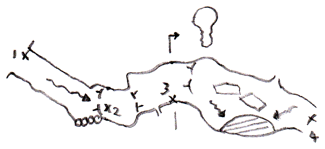
Secondly, one member of the team will draw diagrams of the passage wall shape and ceiling/floor shape, as well as cross sections of the passage (cross sections are not normally done at every station). When the centreline has been plotted, the drawings are then laid over it, corrected to allow for the actual directions. This may be done by hand, or better, using a computer program. These can then be exported either as a normal image, or better, as a vector graphic, to allow them to be drawn at any size, or adjusted later to allow for any new loops that are discovered.
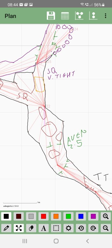
Modern cave surveys are often done using digital measuring devices, such as a DistoX2 or the comically named Shetland Attack Pony, commonly referred to as a Disto survey. These use a laser range finder (tape measure) to measure distances, a multi-dimensional digital magnetic compass and inclinomiter, to perform the same measurements as traditional surveying tools. They then transmit these to a mobile phone or tablet computer, which can immediately take the data and plot it in a graphical editor such as SexyTopo, TopoDroid or PocketTopo, which allows passage walls and details to be drawn. This is then transferred onto a computer, and redrawn using vector graphics in a program such as Therion (a more advanced program inspired by Survex), or a CAD application; Therion is the most advanced currently available, as it can perform the error correction on the drawings as well as the centreline, allowing automatic corrections when loops are closed. See the guide for using SexyTopo to survey caves.
The benefits of the digital versions are that the surveys are generally far faster to perform, as a single button press can take all the readings at once. Distances and angles can be measured to far higher accuracy and precision than a human can do. The person using the instruments does not have to get their head into awkward positions to look into the instruments, and measurements can be taken towards places that would be considered impossible or too dangerous for a person to go. The feedback is instant - the person drawing the details can immediately see if a measurement looks wrong. And there are no mistakes when reading or writing numbers, since it is all sent directly between devices in digital format with no human intervention. But these types of survey require more complex setup, and more technical knowledge, so traditional techniques are still regularly used. A very rapid digital survey can easily prove more accurate than the best traditional surveys. When taking the same time as a traditional survey, the passage can be recorded in much better and more accurate detail.
Grades are made up in two ways. The first is a number from 1 to 6, or the letter X, which says the quality of the centreline data. The second is a letter 'a' to 'd', which says the quality of the passage dimension drawings. Typical grades would be 1a, 1b, 2b, 3b, 3c, 5c, 5d, or 6d. The following may not be official descriptions of the grades, but they are put into normal terms to make them more easy to understand. The official descriptions can be seen on the BCRA website.
The grades talk about how precisely you use the surveying devices - reading a compass bearing to the nearest 1 degree is better than reading it to the nearest 5 degrees, and reading a tape measure to the nearest metre is a lot worse than reading it to the nearest centimetre. They also talk about station position error; when you take a measurement to a point in space (such as the surveyor's nose when standing at that position), how perfectly can you place the measuring devices into that position when taking the next reading? Did that person's nose move by 50 cm as they turned around? Lower grade surveys allow you to use floating survey stations; where you use a position in the air above the floor as the station, and try to keep the tools in the right position for the next readings. Higher grade surveys require you to use permanent features that cannot move, such as a boulder or rock flake, or temporary tripods that remain perfectly still as each reading is taken. Modern surveys often use natural features like rock spikes, temporary rock piles, or small dots that are painted onto a wall using correction fluid (Tipp-Ex) or nail varnish. Some will use small paper notes left at a natural station so that they can be found again. Permanent stations - stations that might need to be used at some distant future date - may have their locations marked with a distinctive chisel mark or a small metal/plastic fixing, so that they will survive weathering for as long as they might be needed, and can be easily identified. For best results, measuring devices should be placed so that their measurements are taken from as close to that point as possible.
Since most stations end up getting used more than once - for a leg coming into them, and a leg going away from them - each time it gets used, the measuring tools must be placed within half the station-position-error distance from the station itself - a sphere with a diameter the same as the station position error. This means that in the worst case, the distance between the two versions of the station is no more than the permitted station position error. For a station position error of ±10cm, the measuring devices should be 5cm from the station at most, which would mean that the legs might be 10cm too short or too long in the worst cases.
When trying to aim for higher grades, note that it will often be impossible to position the measuring point of the device exactly on the actual station. If a device is 5 cm across, and takes its measurements from the middle of its box, then it will not be able to get within 2.5 cm of a dot that is painted on the wall when measuring parallel to that wall, so the grade 6 station position error would be used up by the size of the device itself.
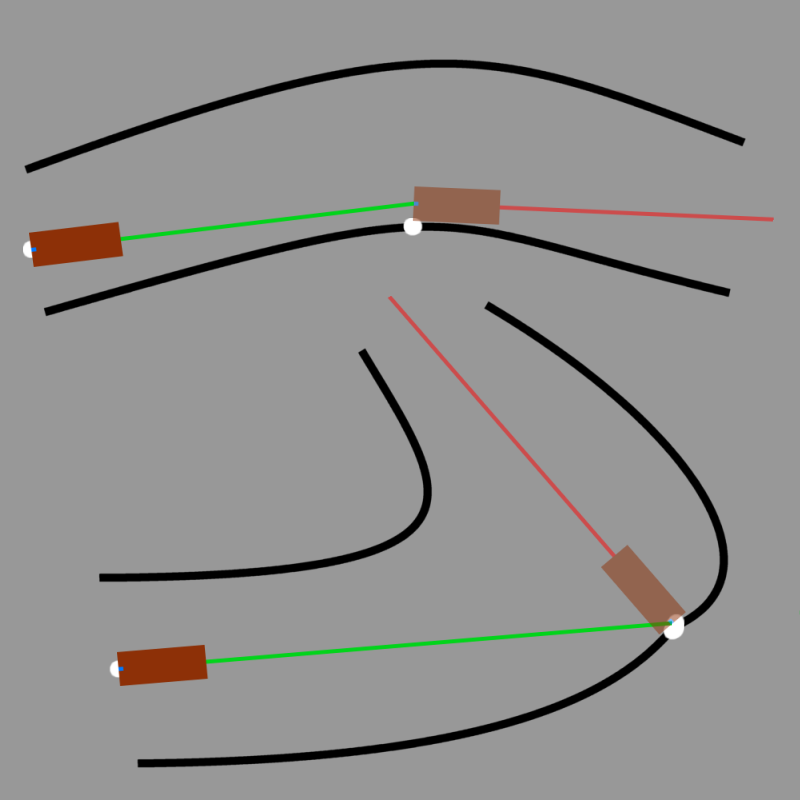
To counteract this error, measurements towards a station need to be taken to a point the same distance away from the station marker as the measuring devices will be positioned for the next readings from that station. As a real example, a DistoX2 normally takes its measurements from the middle of the base of its case, about 1.5 cm away from the back face of the device, so when taking measurements parallel to the wall, it will always have a 1.5 cm position error at best. With a DistoX2, when the legs are parallel to the wall where the stations are placed, the measurements need to be taken to the point that is 1.5 cm from the wall instead, as that is where the next measurements will be taken from. A sighting card can help to give a real station positioned the right distance away from the dot marked on the wall. When taking measurements perpendicular to that wall, the measuring point of the device can be positioned exactly on the dot marked on the wall. Therefore, this needs to be considered at each station.
The official survey grades do not mention loop closures at all, as they relate only to how well you use the surveying tools; the precision of the readings, and the accuracy of the station placement. However, surveyors will see how well they managed to adhere to their target grade by how big the error is after closing a big loop. A loop of 100 metres might have the two ends of the loop misplaced by 1 metre (horizontally or vertically). That would be a 1/100 or 1% error. The grades also do not specify exactly how to calibrate devices, but surveyors often use better approaches for calibration at higher grades.
The grades do not really apply to the resulting survey. They grade the data used to create it. While major features do have to be accurately placed in order to get "d", that is the only requirement. A survey can also mix data of different grades. In most cases, the grade for the majority of the data is used for the overall survey grade, but if a critical part of the cave, such as its entrance series, relies on low grade data, that could reduce the overall grade of the survey. In most cases, a survey that mixes data of different grades will have each little piece of lower grade data identified on the survey with a visible label, to show that the data for that passage is of lower grade.
Note that loop closure errors can be fairly high for loops of only a few legs (such as 5% to 10% for a loop of 3 legs). This is not usually considered bad enough to reduce the grade from 5 to 4. On longer loops, an error of that magnitude would usually require a resurvey, or reduction of survey grade.
The standard grades were created before the invention of digital devices like the DistoX2, and they are aimed primarily at manual devices. It is possible to use a digital device very poorly, typically by failing to calibrate it properly, or calibrating it to low accuracy (anything greater than 0.5% calibration error is considered bad for a DistoX2, while 0.2%-0.3% is extremely good). It is also possible to position it very poorly next to a station. However, standard use of a digital device like these will typically produce readings at far higher precision than any of the standard grades, as long as it has been properly calibrated, and station position errors are kept low. Therefore, a Disto survey will typically be above grade 6, and can often beat the results of a grade X survey for surveys with a lot of short legs. The grade of such Disto surveys should be stated as grade 6 (simply because the standard grades do not offer anything more appropriate).
In practice, testing has shown that leap frogging does not normally produce any significant improvement to the overall accuracy, so it is common not to use leap frogging for Disto surveys. However, it is possible for devices to go out of calibration randomly, or to be affected significantly by magnetic rocks or metalwork. For this reason, it is best to use back-and-forward sightings, where each leg's measurements are taken in the forward direction, then confirmed by re-taking them in the backwards direction, either as a full leg or just a single splay; if the two do not agree with each other, something went wrong, and the calibration or measurements should be performed again. Whether or not a surveyor chooses to use this approach is not mandated and does not affect the grade, but mistakes can be detected more quickly when using it. An alternative method is to take one reading, then roll the device onto its side and take the reading again, which should not change the result if it has been calibrated correctly; this detects calibration issues but does not detect magnetic rocks as reliably as a back sighting.
Wall measurements can be taken using any of the standard lettered approaches. However, it is common to use the approach of splays. These are measurements taken towards the walls, celing or floor in any direction from a station, showing every single point where the wall outline bulges significantly out or in, or where there are important features to draw. Is is therefore extremely easy when using a Disto-style device to achieve passage detail grade d, without needing to create as many stations as traditional surveying would need to achieve that same grade. In fact, this can easily surpass traditional surveys, as every feature can be acurately located, even down to the positions of prominent stalactites or boulders. Grade 6d is therefore a normal grade for Disto surveys, something that would only have been achievable by the most dedicated traditional surveys.
Traditionally, surveys were plotted and drawn up by hand. The first batch of data came in, it would be plotted, and the walls would be drawn. Then more data came in, and a loop would be closed. The centreline could have the error distributed over the loop, and the passage redrawn, with all the old drawings being discarded. Or the error would just be distributed only into the new data, forcing that section to absorb all of the distortion, and bending it out of shape significantly, leaving the original data untouched. Depending on how long the loop is, how big the error is, and how short the new piece of data is, the distortion of that new data might be enough to completely misrepresent the layout of the passages, and reduce its grade. However, the grades apply to the data, not the resulting survey, so the grade would not be changed, even though there is now a substantial error in part of the survey.
When closing a 3 km loop which has a 10 metre loop closure error (a 0.33% error, well within grade 6), with just 5 metres of new survey data, that new piece of data could be stretched to 15 metres, a 200% error. Or the passages could be found to be on opposite sides from each other. Changing 3 km of drawings is a painstaking task, and is unlikely to happen. The more loops that get closed before drawing up the survey, the less chance of a new loop causing such disruption, but surveys rarely get drawn up that way. As a result, grade 6 data can end up with a 200% error at one point, without the survey grade showing that anything is wrong.
When digitally drawing up a survey, Survex could be used to export a centreline, which can be loaded into a CAD package to draw the walls. This approach is used for many surveys, but it suffers from the same problem. In fact, Survex is designed specifically to allow this kind of issue, as it can be told to freeze the old data as it would have appeared before a new loop is closed, so that the new loop is forced to absorb all of the error.
This problem affects a very large number of surveys, from old style drawings like the Gaping Ghyll/Gill survey (where one passage in Hensler's Series got distorted very heavily to absorb the cumulative errors from other parts of the survey), to modern surveys like Ogof Ffynnon Ddu. Yes, that fantastic survey of Ogof Ffynnon Ddu that we all marvel at when visiting the South Wales Caving Club, is drawn up in a CAD application, and new passages have to absorb any loop closure errors from older parts of the survey (but at least there are so many loops in that survey already that most of the distortions have been ironed out).
Therion was produced to solve this problem. It uses Survex to close loops, then it applies the distortions to the passage walls and feature drawings too, based on how much the centreline near them was distorted. This means that the entire surveyed loop can have its 0.33% error, and that 5 metre set of data can be adjusted to 5.017 metres. The old surveyed passages will move into their newly calculated positions, and the distortion will be invisible. This is why Therion is the recommended application for drawing up cave surveys.
Compass is a rare application that does not use Survex's approach for loop closure; instead it closes loops in sequence depending on how bad their error is, pushing most of the error into the worst loop. This is very similar to the approach that was used in hand drawn surveys before Survex was created, and as a result, Compass recreates the old problem, but in a way that puts the errors into the worst offending loops, rather than just the most recent loops. It could be argued to be a more honest approach, since it means a well surveyed loop does not have to be modified by a poorly surveyed loop, but most other applications prefer Survex's approach. Survex and Therion both allow each piece of the data to specify its quality (standard deviation), so that errors can be distributed more appropriately, allowing a poorly surveyed section to receive most of the correction when a loop is closed.
Sumps are normally surveyed using a simple dive compass, a standard diving depth gauge, and a length taken from markings on the dive line. The lengths are relatively inaccurate, since the length markings on a dive line are fairly low resolution, and when the line is wrapped around rocks or bent around corners, its lengths can be altered. The compass readings are generally taken from the direction of the dive line compared with a nearby dive compass, since silt often obscures the view of the next tie-off point (which becomes a station). Depth gauges are fairly accurate at shallow depths as long as they have been calibrated to fresh water (or salt water for marine caves), with a 1% + 30cm error being considered normal and 3% + 30cm being acceptable. At deeper depths, the error can increase. The diver needs to position the depth gauge next to the station in order to get the station's depth rather than their own body depth. The resulting accuracy and precision of all three measurements are quite low. Nevertheless, this is how surveys of sumps are usually done. This type of centreline survey approximates grade 3 or 2, and the walls are often drawn at grade a or b. The altitude can be reliably measured from the water surface at each end of a sump, which must be at the same level (except in sumps with very strong current). Survex and Therion can both use this type of data.
An automated device such as MNemo can be clipped onto a dive line, detect the compass bearing, depth or inclination, and then count the length of the dive line as the diver pushes it along. This needs to be removed from the dive line and clipped back on it again on the other side of each tie-off point, which it can use to detect the fact that it is at a station. A small amount of the length goes missing at the station because of this, and the compass bearing, depth and inclination measurements have the same issues as before. The accuracy of MNemo is relatively high, roughly equivalent to grade 3. It cannot perform any kind of passage detail measurements, so grade 3a is as good as it gets.
Alternative automated devices exist, such as the SEACRAFT ENC3. This particular one works using GPS when in contact with the surface, then gyroscopes, accelerometers, compass and depth gauge underground or underwater. Its design seems to be aimed at the use of scooters, rather than being handheld. The compass has only 3-5° accuracy (unless specifically calibrated), and the depth gauge has 0.3m accuracy. Part of its operation uses a speed sensor which detects water flow, so its results vary depending on the current within the cave, and its accuracy is 2% when moving at scooter speed (and likely far worse at slow speeds). The main accuracy limitation is the quality of the inertial sensors, which will become progressively worse over time, so the accuracy decays over longer dives. Even a high quality device is expected to lose 50 m of accuracy within 15 minutes. The equivalent cave surveying grade is therefore very hard to estimate, and probably equates to grade 2 at best.
It is not generally possible to use digital surveying techniques underwater, since the equipment is not normally waterproof, not generally calibrated for the speed of light through water (measured distances through fresh water are exaggerated by about 10% when using a laser range finder), and cannot cope with the refraction at the water surface or the device's lens. It would in fact be possible for a device to exist that is calibrated correctly for this purpose, but the biggest limitation would be that silt prevents the use of a laser range finder. This approach has been used with a DistoX2 housed in a waterproof enclosure, in the clear sumps of Wookey Hole, setting a distance scaling factor in Survex and Therion, and compensating for the waterproof housing changing the length measurements.
Radiolocation may also be used to correct the horizontal position of passages relative to the surface above them. This is surprisingly accurate, and may be able to locate the horizontal position of an underground point to within just 1.5% of the depth below ground (about 1 metre per 67 metres of depth), and the depth to about 5% of its actual depth, depending on how level the surface is. This is often used to correct the survey of a sump after a poor grade underwater survey. To give an idea; a South Wales cave at 120 metres below surface (a common depth) could be horizontally located to about 1.8 metres, and vertically located to 6 metres. A grade 5 survey might have that much horizontal error within just 180 metres of passage, and that much vertical error within 600 metres of passage. Radiolocation can potentially provide a significant improvement to the accuracy of most big cave surveys, as long as the cave is within about 300 metres of the surface (after that, the signal becomes too hard to detect). However, it does not alter the grade of the survey data. The biggest issue is how well the point on the surface can be located, and how well the survey of the cave itself has been located. Location fixes for many surveys can be quite inaccurate, and surveying from the cave entrance to a radiolocation point creates a new survey error for that piece of surface survey. As a result, radiolocation is not as accurate as it might at first seem.
It is also possible to create 3D representations of a cave using LIDAR scans (thousands of laser measurements taken from each station, usually with alignment markers to allow each scan to be placed relative to the ones around it). This does not produce a standard survey, and any renderings produced in this way cannot be graded with the standard grading system. The "centreline" accuracy can be extremely high, depending on how well stations can be aligned compared with each other. However, there is no real centreline to be measured in most cases, since stations are selected for the best scanning position, not while trying to represent the cave's passage length. The wall renderings can be exceptionally accurate. Therefore it might be possible to obtain a similar accuracy to a grade 6d survey, or perhaps even better, but it does not really make sense to use the standard grades for this type of survey.
Similarly, sonar can be used to measure distances underwater, and this approach is used by the oil drilling industry to measure the size of oil fields. The equipment needed to do this was traditionally too bulky and too expensive to be considered for measuring underwater caves. However, multibeam imaging sonars do exist, and an ROV (remotely operated vehicle or mini submarine) has been used with one to survey some flooded caves with great success - search the web for Vilina Spilja sonar survey to learn more. These surveys are very costly, and still need some way to measure distances, directions and depths to position the resulting sonar pictures. The ROV can use depth gauges, a digital compass, and the length of its tether line to calculate its position at any given point (this is how it was actually done in Vilina Spilja). This means that this most likely could be equated to grade 3d or 4d, depending on how accurately those depth measurements and tether length measurements could be made, but the standard survey grades really were not designed to be applied to this kind of survey. While this is a dramatic improvement over standard sump surveying techniques, it is unlikely that cave divers will have a futuristic wrist-mounted automatic sonar surveying tool any time soon.
The French UIS (Union Internationale de Spéléologie) have their own grading system that has more grades dedicated to approximate surveys, such as ones drawn from sketches, or measured in body lengths or paces. It also concentrates more on how well each device is calibrated and how accurately it is read, but ignores how closely it is held to a station. As a result, the grades cannot be used to directly relate to the B.C.R.A. grades. Nevertheless, they are interesting in that they can say whether loops have been closed to prove that the desired grade has actually been achieved, and whether the location fixes were done accurately. The UIS grading system has its own documentation.
The ASF (Australian Speleological Federation) also has its own grades, which have many more levels for the use of Theodolites. Like the B.C.R.A. grades, it pre-dates Disto surveys. Like the UIS grades, it says how much error should be expected when closing loops, and can say whether this was proven by loop closures. The ASF grading system has its own documentation.