This is not intended as a safety briefing, and should not be used for learning about safety. Training is essential. Take a dedicated course. Do not learn about how to use vertical caving techniques from some guy on the Internet. Do not use this page to learn how to use any of the techniques, it is not intended for training purposes. It is aimed only at the terminology and approaches used in Britain, and specifically in English. It is also intended to be used for historical research into how the various techniques developed, for historical education purposes (see the history section if that is what you are here for). While most of the information here is factual, there is intentionally some (hopefully obvious) humour in here. If you do not know how to detect humour, it is perhaps best to go looking for a more serious guide. I do not claim to be an expert, I am just a caver, documenting what I see.
And even more importantly, do not learn how to use vertical caving techniques from YouTube videos, where some non-expert repeats the bad advice they learned from someone else on YouTube, and makes it sound like they know what they are talking about. Even if someone is an expert, they may be an expert in a different country or a different discipline where the vertical caving practices are different, and incompatible with the approaches used in your own. Or they may have learned from someone else with those same limitations. Or their advice might have been correct at the time they learned it or produced it, but up to date advice might be different. You might never have the chance to realise what was wrong with their advice, before their mistake lands you in trouble. Take a dedicated course in your own country, from someone experienced with vertical caving. Your instructor might notice you making mistakes that books and videos never warned you about, and an instuctor can correct your mistakes before they become a problem. Most caving clubs can offer dedicated courses that are run by a training organisation, or they may have their own training programmes. Contact a local caving club. You can also use highly regarded books to assist in your education, as long as they cover the correct techniques for your local region, but these should be in addition to a practical course. Ask your instructor for book suggestions, and do not learn how to use vertical caving techniques from the Internet!
This page is aimed only at caving. While similar equipment is used in some aspects of rock climbing, rope access and arboriculture, each of these disciplines has its own terminology and ways to use the equipment. Those other disciplines are not covered here, apart from a very small section on the parts of rope access and arboriculture that are relevant to caving. This page does not cover any of the techniques or equipment used to rescue a casualty; attend a dedicated course for that.
If you are looking for a more complete guide, along with safety advice and improvised rescue techniques, I can thoroughly recommend the 2007 publication "Vertical" by Al Warild. It generally uses USA or Australian terminology, however, and mentions some techniques that are not compatible with British caving. Take. A. Dedicated. Course.
This page was written by Tarquin Wilton-Jones.
If you want to cite any of this work rather than simply linking to it, please refer to me with my name written the way I have written it. My name must not be reduced or modified to "Wilton-Jones", or "Mr. Wilton-Jones", or "Wilton-Jones, T." or "T. Wilton-Jones" or "Wilton-Jones, Tarquin" or anything else like that. However, if you need to refer to me multiple times through your text, then subsequent mentions can use my personal name "Tarquin" for brevity. I am not my father, and my unique identifier is my name as I wrote it, not some other random portion of my name. You may change my name's ending, in accordance with the grammatical requirements of your language, but please do not translate or transliterate my name into your language. My name should not be roughly approximated in Katakana, Cyrillic or any other language's name approximation, for example (not least because nobody ever gets it right when they do). Knowingly getting someone's name wrong when they have told you how to get it right, is extremely rude.
Please note that Harvard, Chicago, Vancouver, APA and MLA referencing are incredibly rude and insulting to many cultures and individuals, no matter how respectful your institution may consider them to be, as they disregard cultural and personal significance. That approach to referencing is not acceptable in this day and age, and really never should have been acceptable, since it is based entirely on a subset of Western culture, as if the rest of the World and personal significance does not exist. Institutions that still insist on using them need an education in diversity. More than half of the World's population are offended by having their name modified in that way, while none of the World's population are offended if you refer to them they way they ask you to. You should not accept any kind of referencing style that insults the very people whose work you are building upon, and if your institution or publisher forces you to, then you must not use this page as a source, since you are unable to credit me or refer to me properly. Some university researchers that I know have even been forced to change their name by deed poll to remove their family name, specifically because of how insulting they find that style of referencing to be when it is removes their personal name, or puts it in the wrong place.
This page was originally intended to be a simple glossary for beginners, but turned into a compendium for all vertical cavers, covering equipment and methods from most aspects of vertical caving (except rescue), and the history of its development. The majority of this page's content was written between 5 May 2022 and December 2023, with most of the historical research taking place during 2023, but it is a living document, and historical research has continued throughout its lifetime. It was first published on 1 January 2024. This could not have happened alone, and a great many people helped to make this page possible, listed here in order of which section(s) they contributed most to. In particular, special thanks to:
Also known insultingly as "silly bits of string". Used to make pitches not be dangerous. Let's face it, if you need this one explained, you are beyond help here.
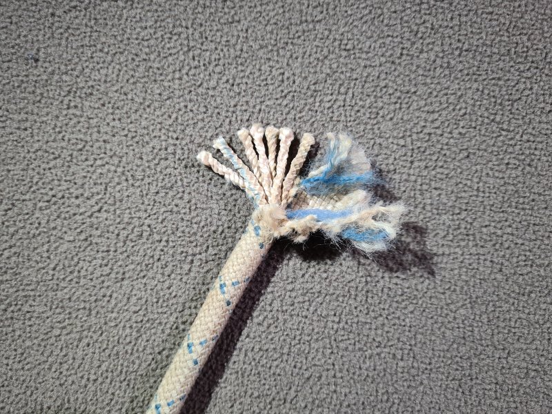
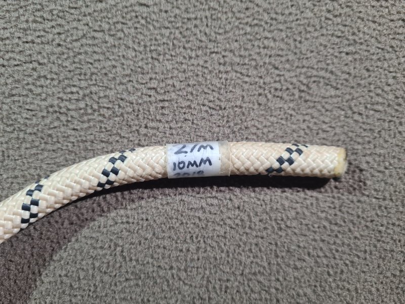
Ropes designed for caving are extremely strong, with a minimum breaking strength around 10 times higher than they will ever experience during use. They are made from a woven "sheath" (or "mantel") of fabric around several "cores" (or "kern"), known as kernmantel construction (or kernmantle if you prefer the USA spelling). The sheath binds the cores together for the best performance, allows the rope to pass nicely through various pieces of equipment, allows the equipment to grip it properly, and protects the cores, while also providing about 20% of the strength. The cores are the actual strong part, providing about 80% of the strength of the rope. While kernmantel is the only construction used for SRT, other constructions may rarely be used for fixed handlines, most commonly hawser laid, with braided/plaited and cable laid occasionally being seen.
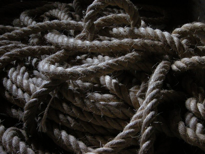
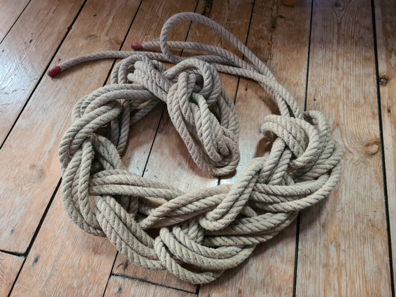
Hawser laid ropes are twisted from three strands, with the twists visible on the outside of the rope, very common with low quality ropes sold for household purposes. Shroud laid is the same as hawser laid, but with 4 strands, and might have a thinner central core strand. Cable laid ropes are made from three hawser laid ropes twisted into a final rope, with a much tighter twist. Hawser laid and shroud laid ropes have opposing twist directions for the strands as for the overall rope, usually "left hand" for the strands, and "right hand" for the overall rope, but either direction is possible. Cable laid ropes have one twist direction for the inner strands, opposite for the hawser laid step, then back to the original direction for the overall rope. Braided/plaited ropes are made from several strands that are all woven together like the sheath of a kernmantel rope (but often with much thicker strands) without any cores, passing from the middle of the rope to the outside of the rope at various points in the weave. These may also be known as hollow braided/plaited ropes, if the weave does not cause the strands to pass into the middle of the rope at any point, resulting in a woven tube which can easily flatten into a ribbon. Double braided/plaited or double sheathed braided/plaited ropes are like a braided/plaited rope in the core, with a woven sheath outside, or two layers of woven sheath. They may sometimes have a few non-braided/plaited core strands in the middle of the inner braid/plait, like a standard kernmantel rope. Technically, double braided/plaited ropes are a type of kernmantel rope, as they have both a sheath and core. Hawser laid, shroud laid, cable laid and braided/plaited ropes all expose the strong rope fibres on the outside of the rope at some point, allowing all of them to be damaged by abrasion, potentially weakening the rope significantly; they do not protect the cores. All of them except braided/plaited ropes also untwist significantly when loaded, causing a very uncomfortable spin when used with SRT. Cable laid ropes are normally too thick for SRT, but less prone to untwisting, because the opposing twists fight each other better.
Caving and climbing ropes are purpose made, from nylon (polyamide). Polypropylene rope must be avoided at all costs, as it can melt through when exposed to the heat dissipating from a descender, and is much less resistant to abrasion. It melts at just 160-170°C. However, canyoning ropes are intentionally made with polypropylene cores and a nylon or polyester sheath, so that they can float, but these are then expected to be used in wet conditions with slow abseiling so that they do not heat up enough to melt the cores. The strength of polypropylene rope is slightly lower than an equivalent nylon rope. Polyester rope is often intended for maritime usage, and does not provide the shock absorbancy or flexibility that caving ropes require in Europe, but it is more resistant to abrasion. It is often used in American caving, where ropes are allowed to be worse for shock absorbing. Hybrid ropes are possible, such as having nylon cores for shock absorbing, and a polyester sheath for abrasion resistance. These hybrids are uncommon with caving in Europe, partly due to polyester being known for its poor flexibility even when used only for the sheath, and partly because shock loading can cause the two materials to elongate differently (though manufacturers can control that to a degree, and certain constructions can bind the core and sheath to each other). Whichever material is used, ropes are usually cut into appropriate lengths, and the ends are then melted to prevent them from fraying.
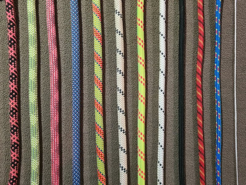
"Static/semi-static/low-stretch" (a bit stretchy) ropes are used for SRT, which will stretch about 4% when a person hangs on them. American ropes may stretch a lot less, such as just 3% with a 400 kg load - these provide virtually no shock absorbing qualities. Manufacturers aiming at both markets will often call European static ropes "semi-static" and the American static ropes "static", but some refer to European static ropes as "static". "Dynamic" (more stretchy) ropes are used for climbing or belaying, and will stretch about 10% when a person hangs on them. Ropes are generally white with colour coded stitching showing the diameter for caving, and brightly coloured for dynamic ropes, but static ropes can sometimes be colourful too. Caving ropes are classified by the EN 1891 standard as "type A". There are also intentionally lower quality "type B" static ropes which are not designed for caving, so these are generally marketed for other purposes. However, these may be used for ultralight rigging.
10 mm and 10.5 mm are the most common diameters, 11 mm is very thick and slow, 9 mm and 9.5 mm are used sometimes. 7 or 8 mm ropes are used only for expeditions when low weight or low size is important, but they are very fast. Thinner ropes are much weaker, and suffer a more severe loss of strength when damaged. They are normally much easier to damage, since the thinner rope normally has a thinner sheath. Rope diameters and weights are normally measured when holding a 10 kg load, and an unloaded rope might measure 1 mm more than the stated diameter. A rope may stretch significantly as it is loaded with 10 kg, so the actual weight per metre of the unloaded rope may be about 2% heavier than its stated weight per metre. This can be over 5% with dynamic ropes or thin ropes. This measurement approach was first standardised in 1972 (ISO 2307, which used a force of diameter2 * 1.25 N, about 12.742 kg with 10 mm rope), and the current loading weights were only standardised in 1998 (CEN EN 1891 and CEN EN 892), so it is not possible to directly compare the weights of ropes from before then. A modern 50 g/m climbing rope may actually weigh the same as a 53 g/m rope from 1950, depending on how the company measured the weight in 1950. (USA ropes can also be measured using ASTM D4268 since 1983, which used a force of diameter2 * 1.38 N, about 14.067 kg with 10 mm rope. Methods that base the force on the diameter end up with a chicken and egg problem; they cannot know the right force until they know the diameter, and they cannot know the diameter until they apply the right force. So ASTM D4268 bases the force on the unweighted diameter instead, meaning that it could use 17 kg with a 10 mm rope that becomes 11 mm when unloaded. The ISO standard does not say how to resolve the conflict, and just treats it as an approximate diameter. This all means that USA ropes can actually be thicker and heavier than a European rope with the same stated diameter and weight.)
Ropes are connected via knots to carabiners and maillons, or more rarely directly to anchors or naturals. Most knots reduce the rope strength by about half, and since knots are needed, the rope strength when it is being used can be considered about half its stated minimum strength. They are always far stronger than they need to be to support a caver, since the movements, shock loads and odd directional pulls on the rope cause the stress on the rope to be a substantially higher than the caver's own weight, and water or damage cause the strength to be decreased. A caver who is abseiling or prusiking will normally put a maximum of just over twice their weight (including wet clothing and any tackle bags they are carrying) on the rope if they bounce around as much as possible, and a common suggestion is that equipment should be rated to at least 5 times the load it is expected to encounter, as a safety margin. 15 kN is generally considered the minimum strength suitable for caving ropes. 8 mm and thinner ropes are usually marketed as accessory cord, meaning that they are intended for hanging equipment from, rather than cavers - these would be the "type B" ropes. Thinner dynamic ropes might be sold as "half rope" or "twin rope", meaning that climbers are expected to rely on two of them at the same time; this is something that makes very little sense with Alpine rigging used in caving but which can be used by some descenders, such as a rack. Thinner accessory cords are normally called paracord or parachute chord, and usually have a more flexible sheath. The following chart gives the strengths for some popular rope brands, but each brand has its own individual ratings:
| Diameter | Unknotted strength | Knotted strength for figure of 8 on a bight | Weight |
|---|---|---|---|
| 12 mm | 38 kN (3.87 tonnes) | 25 kN (2.55 tonnes) | 93 g/m |
| 11 mm | 34 kN (3.47 tonnes) | 22 kN (2.24 tonnes) | 79 g/m |
| 10.5 mm | 28 kN (2.86 tonnes) | 18 kN (1.84 tonnes) | 72 g/m |
| 10 mm | 25 kN (2.55 tonnes) | 16 kN (1.63 tonnes) | 66 g/m |
| 9.5 mm | 24 kN (2.45 tonnes) | 15 kN (1.53 tonnes) | 59 g/m |
| 9 mm | 23 kN (2.35 tonnes) | 12 kN (1.22 tonnes) | 53 g/m |
| 8 mm | 15 kN (1.53 tonnes) | 10 kN (1.02 tonnes) | 43 g/m |
| 7 mm | 11.7 kN (1.19 tonnes) | 7.7 kN (0.79 tonnes) | 32 g/m |
These ratings are for new rope, not rope that has been used for years, subjected to shock loads, or exposed to the elements. The ratings are also for ropes that are dry. Once wet, a rope loses about 10% of its strength, and caves are often wet places, so this is how caving ropes are expected to be used. A wet rope cannot absorb as many shock loads, but this is something that caving ropes should not experience in normal use anyway, so being wet is not considered to be a problem for caving ropes. A rope that has a damaged sheath can still normally support enough weight to be relied on. However, since a split sheath can slowly creep down the cores, it can make it difficult or impossible to use the rope safely, and makes it far more likely that the cores will now also be damaged. Core strands that are holding a load can cut through surprisingly easily if they come into contact with a sharp surface. You never want to see the cores, and a rope damaged to that degree should be cut into shorter pieces to remove the damaged section.
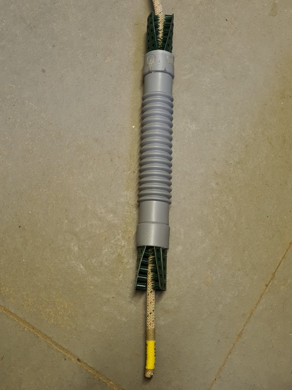
It is possible for the sheath of a kernmantel or double braided/plaited rope to slip down the cores a little during use, bunching up more at one end than the other, or leaving part of the sheath with no cores. Caving ropes are usually made with a fairly tight sheath to minimise this effect, but in bad cases, the sheath may need to be cut to a better length to match the cores, and the end remelted. The sheath protects the cores, but a rub point can still wear through the sheath. Because the fibres in the sheath all wrap around the cores, all sheath fibres are exposed on the same side of the rope, within a very short distance along the rope. A rub point on one side of the rope can damage all of the sheath fibres, causing the sheath to be severed completely, exposing the cores. When a device such as a descender or ascender pulls on a rope with a severed sheath, the sheath can slip down the cores and bunch up. Once the sheath has been worn through enough to expose the cores, the cores can also be damaged by the rub point, but with kernmantel ropes, only one set of cores is initially damaged at a time because the cores stay at one position in the rope, and the next ones are not exposed until the previous ones have worn through, or the sheath has been severed completely, allowing the cores to spread out on the rub point.
Double braided/plaited ropes have the advantage that they can be spliced much more effectively than standard kernmantel rope, and they hold their shape better when bent at sharp angles. However, they are often less flexible, which makes them less convenient for tying knots, or can make knots more likely to come untied. They can be heavier, and they are not normally as dynamic, making them generally worse for absorbing shock loads. They also have the disadvantage that the core fibres also wrap around, so they are all on the same side of the rope within a very short distance. As a result, a rope rub on the cores on one side of the rope can quickly damage all core fibres at the same time. Many double braided ropes are specifically designed to be used for splicing, which needs the core and sheath to be easily separatable for construction of the splice, and this means that an accidentally severed sheath slides down the cores far more easily than with a rope designed for caving. This is particularly noticeable with ropes designed for sailing. Some ropes use a small amount of glue or extra threads to bind some of the core strands to the sheath, making the sheath far less likely to slip down the cores during use or if it is damaged. This is normally more effective with double braided/plaited ropes than with standard kernmantel rope. Double braided/plaited ropes are often preferred for arboriculture and sailing.
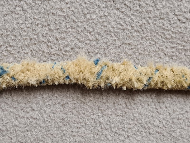
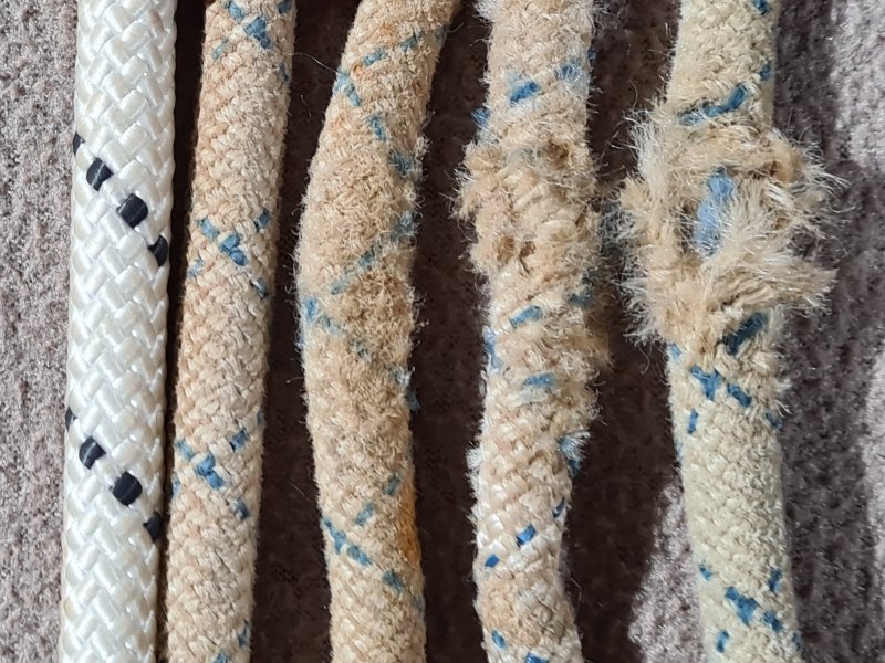
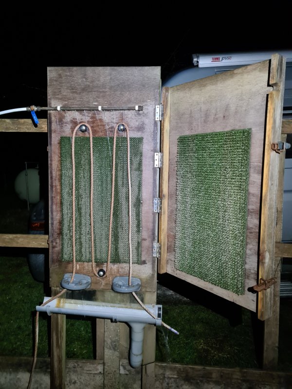
Over the years, being bent and squashed around through regular use (SRT or just being tied in knots) causes damage to the rope fibres. Contrary to popular belief, standing on ropes does no discernible damage, as long as the ropes are not on a sharp surface. The pressure exerted on the rope by SRT is far higher than a shoe. Mud being forced into the fibres by SRT on muddy ropes increases the damage to the fibres of the sheath (but the mud does not seem to reach the cores as long as the sheath is intact), which is why rope washers exist. This causes shrinkage, and turns the rope sheath furry. Once this becomes excessive, it is time to retire a rope, even if it still passes drop testing. If the rope becomes too stiff to pass easily through a descender, or such that it feels like "wire", it is time to retire it. If a rope develops soft spots, so that it no longer holds its round shape, and can be squashed between fingers much more than the rest of the rope, it should be retired immediately or cut into smaller pieces to remove the soft section, since even though it probably can still hold a person, it has been weakened significantly at that point. If a static/semi-static rope has been subjected to a significant shock load, it should be retired immediately. Manufacturers are not keen to say exactly what counts as a shock load bad enough for this to be needed, but anything above fall factor 0.3 might be considered bad enough (for European ropes). Fall factor 1 is definitely bad enough.
Ropes are extremely susceptible to certain chemicals, particularly acids below pH 4, alkalis above pH 12, sulphuric acid (battery acid in car batteries and old caving lamps, some drain unblockers, some aquarium cleaners), hydrochloric acid (stomach acid, concrete cleaner, rust remover), nitric acid (dishwasher liquid, household cleaners), sodium hydroxide (caustic soda, lye, drain cleaner, various kitchen cleaners) and hydrogen peroxide (various kitchen cleaners, hair bleach, whitening toothpaste, contact lens cleaner, acne treatment, glow sticks, some aquarium medications, plastic restorers), where the rope is dangerously weakened and the damage is not externally visible. Other dangerous chemicals are formic acid (wart remover, limecale remover, ant bites), phosphoric acid (concrete cleaner, fertiliser, preservatives), particularly strong vinegar (fish and chips, ketchup, salad cream, glass cleaner, silicone), most other acids (including ant poison and climbing grip cleaner), bleach, petroleum jelly (vaseline), iodine (wound cleanser), fluoroalcohols (uncommon solvents) and phenols (some disinfectants and strong detergents). Any rope that has been exposed to these chemicals needs to be retired immediately. Drink, fruits and sweets that contain citric acid (orange juice, lemon juice, most soft drinks, sour sweets), malic acid (apple juice, sour sweets) and tartaric acid (grape juice, wine) also have a weakening effect, and while this is typically less severe than some other acids, it depends on the concentration, and the length of time that they are in contact with the rope. Petrol and oil seem not to have any serious effects, however. Tomato juice and coffee are not acidic enough to be considered harmful. Polyester copes with slightly stronger acids and alkalis than nylon, and polypropylene copes with even stronger.
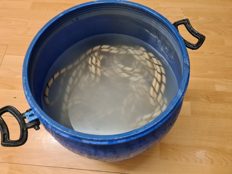
Wet ropes are supposed to be gently dried over the course of a few days at room temperature (40°C is as high as it should get, and it is better to be below 30°C). They should not be dried with heat, such as by putting them on a radiator (60-90°C), in a tumble drier (70-75°C) or out in the sunshine. According to Mammut, this is because the heat causes fibres to become more brittle, and wet fibres are more vulnerable than dry ones. The rope will lose some of its dynamic properties, and age prematurely, becoming stiff and furry, with associated shrinkage, considerably faster than if it had been dried correctly. This will cause the rope's strength to be reduced, and make it less able to survive a shock load afterwards. Even when dry, repeated exposure to high temperatures eventually degrades the rope's strength or shock absorbing abilities. For this reason, Mammut recommends storing ropes between -10°C and 30°C. Anecdotal evidence from people who have made that mistake suggests that short term accidental exposure to the heat of a radiator (such as a few days) does not appear to cause significant damage to a dry rope, but testing has shown that the rope has reduced performance similar to it being wet if it is actually used at those temperatures. Ropes tested at 50°C show the same results as ropes tested at room temperature. Hot or boiling water should be avoided, temperatures of 150°C or more will damage a rope to the point that it loses around half its strength, and very high temperatures of 220°C or more, such as a flame or hot oven, will melt rope. Exposure to sunlight for a long amount of time degrades ropes, largely because of ultraviolet (UV) light, with the sheath being affected much more than the cores. Testing with ropes kept in Mediterranean levels of sunshine for 3 months showed a loss of strength by around 10%, and reduction in shock absorbing abilities by 25-50% (in terms of drop testing). A day in the sun at the top of a surface shaft is negligible, but several months is not good. Ropes left underground for years or even decades in cold, dark, damp conditions are often still usable, as long as they have not been damaged through use or from being swung into a wall by moving water.
Accessory cord can be made from higher performance materials. High-modulus polyethylene (HMPE), also known as ultra-high-molecular-weight polyethylene (UHMWPE), commonly known by the brand names Dyneema, Spectra or AmSteel, may be used to make especially strong cords and slings. It is stronger and lighter than steel for its size, and does not decay when exposed to UV from sunlight. It is not suitable for SRT because it is extremely slippery and does not provide enough friction for use with descenders. Even if it did, the heat from the descender could melt it, since its melting point is even lower than polypropylene, at just 140-150°C. Knots do not grip well, and can slip during use when loaded. Knots also weaken it very significantly, as much as 70-80% for some knots that are used for SRT, so it needs to be stitched or spliced instead to make loops. Dyneema cord can be as much as three times as strong as nylon for the same cross section, though with kernmantel construction, it might be around twice as strong (so an unknotted 5 mm Dyneema cord is about as strong as 7 mm nylon cord). That benefit is lost completely once it is knotted, and with many knots, it will then be significantly weaker than nylon. Like steel, it does not stretch significantly at all, so it has no ability to absorb shock loads, and would result in severe injuries if anything goes wrong, such as a failed anchor. When shock loaded, its strength is significantly lower than its normal maximum, and its maximum strength can only be obtained during an extremely slow pull. Aramids such as Kevlar, Twaron and Technora may be used for some climbing accessory cords and sailing ropes, or for protecting heavily worn parts of SRT gear, but are not used for SRT ropes for the same reasons. While they can cope with far higher temperatures than other ropes, they deteriorate very quickly when exposed to UV in sunlight. However, they are sometimes used in the sheaths of canyoning ropes, and replaced regularly to avoid the issues with UV damage.
How long ago were ropes made? I dunno, how long is a piece of string? Ropes were originally made from plants, animal skin, hair or sinew twisted into a long thread. This was developed separately by many cultures around the world, and used to tie primitive axe-heads to sticks, tie animal skins into clothing, restrain animals, hold pottery, haul blocks and build bridges. A probable needle was found in Sibudu Cave, South Africa, dating from 59000 BCE. The thread is likely to have been made from sinew or plant fibres, but no specific evidence was found. The earliest known example of rope was created by Neanderthals in 48000 BCE, and was found in the Abri du Maras cave in the Ardèche region of France. It was made from tree bark fibres, and was probably hawser laid or two-ply, but is far too small of a sample to be certain. A sewing needle from the same era was found in Денисова пещера (Denisova Cave) in Siberia, Russia, which had been made by Denisovans, rather than humans. This implies that they were using a thread of some kind, but no further details are known. Another from 47000-42000 BCE was found in Пещера Страшная (Strashnaya Cave), Siberia, Russia. Another needle from 45000-39000 BCE was found in Potočka zijalka (Potok Cave) in Slovenia. Tools for making actual rope (not sewing thread) were found in the Hohle Fels cave in southwestern Germany, dating from 38000 BCE. The Caucasus mountains have evidence of needles dating from 38000-33000 BCE. Needles from either 33000-27000 BCE or 28000-21000 BCE (depending on the accuracy of the analysis) were found in caves at 小孤山 (Xiaogushan) in China. Flax was being used to make ropes in Dzudzuana Cave in Georgia, Europe, in 32000 BCE. Needles were widely used throughout Africa, Asia and Europe, but they were used with very fine threads, rather than rope.
Imprints in clay show that rope was used in what is now the Moravia region of the Czech Republic in 26000 BCE. The same region has imprints of fishing nets with knotted strings made from hemp and nettles in 25000 BCE. Remains of three pieces of twisted fibre cords dating from 17000 BCE were found at Ohalo II, in the Sea of Galilee in Israel. Fragments of rope from 15000 BCE were found at the Lascaux caves in southwestern France. Fishing cords of an unknown fibre were made in 10000 BCE in Israel. Ropes were made from grass at the Coves de Santa Maira caves in Valencia, Spain, in 10000 BCE. Hawser laid and two-ply rope was made from dogbane (Indian hemp) in Lamona Rockshelter, Washington, USA, in 8000 BCE. Hemp was used for textiles in China since 8000 BCE. In 4200-2700 BCE, Neolithic miners at Rijckholt Flint Mine (now Netherlands) are thought to have used ropes to access their mines, but there is no known evidence of what the ropes were made from. Ropes of unknown construction were also used at Harrow Hill, Cissbury Ring and Grime's Graves in southern Britain in 4000-2200 BCE, 4000-3500 BCE and 2650-2300 BCE respectively (various sources say they were probably made from plaited leather, but there is no actual evidence to support that conjecture). Egyptians were making ropes from reeds in 4000 BCE, particularly hawser laid ropes made from papyrus. By 4000 BCE, braided/plaited ropes were being made in Asia. Twine cords made from flax, dating from 3900 BCE were found at Lake Constance, Germany. Leather was used to make cords for such a long time that its earliest known use cannot be known. However, a pair of leather shoes were found in the Areni-1 cave in Armenia, dating from around 3500 BCE, which were laced using leather cords. The oldest leather known from Britain dates from 2576-2464 BCE. Ötzi the Iceman from Italy had a hawser laid sinew bowstring, in 3230 BCE. Swiss Corded Ware people had many samples of hawser laid and two ply cords, dating from 2800 BCE, which they then spread to a large part of Central, Eastern and Northern Europe. Hemp rope emerged in 2800 BCE, in China. It was then used in Egypt in 1500 BCE, using specialised rope making tools that they had developed. Egyptian ropes were typically hawser laid or two-ply, and use the same approach as modern hawser laid ropes. Ropes made from lime bast, fibres in the bark of lime trees, were used in the Christian von Tuschwerk mine at the Salzwelten Hallstatt salt mine site in Austria around 1344 BCE. Bamboo rope appeared so long ago in China that there is no known record of when it was first created, but it was used to make strong ropes around 1 CE, which could be used to make bridges. A 4.5 metre long piece of bronze cable was found preserved in Pompeii, from 79 CE. It consisted of three strands twisted together in exactly the same way as a hawser laid rope, where each strand was made from 15 wires, a 3×15 configuration, giving a diameter of 8 mm. The hand crank used to make hawser laid rope did not appear in Europe until much later, after the end of the Roman empire. Wire making took place in Nurnberg, Holy Roman Empire (now Germany) a person making wire between 1388 and 1423. Ropes became a fundamental part of ships, whose significance grew exponentially during the Age Of Discovery (1500s to 1700s), and this is where a lot of the techniques used in SRT first appeared.
Initially, vertical caving was done using hemp ropes and hemp rope ladders, typically hawser laid. Actual hemp had been used for sailing for centuries, and would have been used for the early phase of vertical caving. In many cases, it was referred to as Italian hemp, due to that being the source of high quality hemp, but it is the same plant that may be grown in other countries. Sisal, made from Mexican agave plants, became available in 1810, and will also have been used for caving, initially in North America. In 1832, wire cables were claimed to have been developed in England. In 1834, mining engineer Julius Albert developed a modern steel cable in the German confederation, now Germany. It had a hawser laid construction with each strand made up from 4 wires, a 3×4 configuration, with a diameter of 19 mm and length of 600 metres. The idea was that when the strands weakened and snapped, the others would continue to work, and the damage could be seen so that the cable could be replaced, while the existing chains failed catastrophically. In spite of this being frequently stated as a new invention, it is the same construction (just a different material and number of wires) as the Romans had been using. Presumably the English cable used the same approach, but no details were given. In 1837, French explorer Stanislas Marie César Famin described Colombian ropes, which were made from liana, agave or strips of leather. Manila hemp had been used by Spanish sailors from 1600, but only became common in America from 1812 onwards, and Europe after 1869. Manila hemp is not hemp at all, but actually from the abacá banana plant, though it functions the same way. This soon accounted for the majority of ropes used for caving. From 1838 onwards, ropes made in Britain from Indian jute became available, but it is not known if these were ever used for caving. Hemp, Manila hemp and jute are all very similar in appearance, while sisal typically results in much lighter coloured and smoother ropes, and users would have known it was different. Lighter cotton and darker jute remain the most common materials for natural twine, with cotton being softer and far easier to break, and jute appearing significantly more hairy and chaotic. The different materials can be approximately ranked in terms of relative strength compared with hemp at 100%, as Manila hemp 90%, sisal 80%, flax 70%, jute 60% and cotton 40-50%, though the actual strength will depend on the manufacturing process. The resistance to abrasion, water and UV also decrease in that order. This explains why hemp was often preferred, and cotton was not used for mountaineering and caving. However, the other materials were still used because of their availability and cost.
A woven sheath had been used in 1845 with hose pipes by American Horace H. Day. The idea behind kernmantel rope, a protective, woven sheath over a stronger core, seems to have originated with flexible drive belts for machines, first patented in 1854 by American Harry H. Matteson, using a woven sheath made from natural fibre over a tougher core made from strong material such as bamboo, rattan or whalebone. Waterproofing liquids could fill the gap between the core and sheath. By 1858, braided/plaited ropes were being regularly manufactured, with American James A. Bazin suggesting a new construction method and machines to produce it. By 1859, kernmantel construction was being used with telegraph cables, optionally using wires for the sheath. (The idea of a woven sheath was also used for packing or wrapping pipes, metal rods or asbestos rods, for industrial purposes, from around 1865.) High quality mountaineering ropes are likely to have originated as fire brigade equipment. Austrian fire brigades were using 9 mm hemp rope for hauling equipment and lowering people in 1877. Also in 1877, fire brigate supplier Conrad Dietrich Magirus from Ulm, German Empire (now Germany), published recommendations for fire brigade ropes. The 17 metre normal length, thread count of 36 and 48 for the two sizes, diameter of the smaller size and weight of the larger size were given, which allows some calculations. Every year, they were tested for strength, using the actual rope, not an offcut. They needed to hold a 300 kg static load, and survive a 75 kg drop test of a 1 metre fall, on the full length of rope, which gives a fall factor of just 0.06. A new rope might survive a fall factor of 0.12. The actual strength of the rope is not stated, but can be calculated based on the quoted thread strength. The knotted strength cannot be calculated, but is estimated based on a typical factor of 65%:
| Diameter | Unknotted strength | Estimated knotted strength | Weight |
|---|---|---|---|
| 10.5 mm | 8.8 kN (0.9 tonnes) | 5.7 kN (0.59 tonnes) | 70.6 g/m |
| 9 mm | 6.6 kN (0.68 tonnes) | 4.3 kN (0.44 tonnes) | 52.9 g/m |
Kernmantel construction with a sheath made from wires or natural fibres to protect central cores was already in use with electrical cables in the USA by 1880, and by 1885 there were already several methods to do so. In 1881, the German and Austrian Alpine Association were using 18 mm Manila hemp rope, which weighed about 133 g/m, for crevasse rescue. The supplier in Vienna, Austria, would colour code a rope thread, and supplied it in 30 metre lengths, which was stated as a normal length. In 1883, American Edward Maynard developed a double braided/plaited rope for use as window sash cord, a type of pull cord. He stated that braided/plaited ropes often had core strands in order to keep the shape of the rope, resulting in a kernmantel construction, but that when pulled hard, the shorter cores would snap, leaving only the woven sheath. His double braided/plaited rope would have the same core and sheath lengths under tension, which would allow the cores and sheath to both support the load at the same time, resulting in a stronger rope. Also in 1883, an American fire escape patent specifically asked for a braided/plaited rope when abseiling, since it would avoid the spinning effect from hawser laid rope. Splices in braided/plaited ropes were described in 1884 by American Leedham Binns. In 1886, American Frank M. Beckford developed a rope using kernmanel construction, with the sheath made from wire, and the core providing most of the strength. The core could be any construction, including parallel strands or hawser laid.
Starting from about 1889, French caver Édouard-Alfred Martel used 14 mm hemp rope for winching. Also in 1889, American inventor Joseph Williams Jr. patented a rope with multiple core strands, and a woven sheath, like a modern kernmantel rope, as well as a variation that used multiple woven layers, like a double braided/plaited rope, or multiple layered braided/plaited rope. The gaps between layers were filled with lubricant that would be squeezed out as the rope was used, and the rope was intended for industrial usage, not caving or mountaineering. Rayon was created from plant cellulose by British chemist Charles Frederick Cross in 1892, but although it is used for ropes, there are no records of it having been used for caving. It was more instrumental in demonstrating how synthetic fibres might be made. (It was used in the original Cordura, but that was probably not used for caving, since it was replaced with nylon in the 1960s.) In 1893, American Hugh Coyle patented a rope with a hawser laid core and woven sheath, as a similar idea to kernmantel rope. In this case, the gap between the core and sheath was filled with a fire resistant lubricant (asbestos!) which would squeeze out of the rope as it was used for abseiling. This idea appears to be a direct copy of the idea Joseph Williams Jr. had patented, but using a different core design. By 1901, kernmantel construction was used for pull cords by American William A. Tucker, with a hawser laid cable core, and fabric sheath.
By 1907, a cable was being used in Gough's Cave in Britain as a fixed handline, to help show cave visitors to climb a steep slope. In the same year (and same book), British caver Ernest Albert Baker of the Kyndwr Club stated that rope should be hemp (not "Alpine club material"). However at the same time, Manila hemp was also described being used for ropes by his club, and so was cotton. The Bavarian section of the German Alpine Club in München detailed their use of ropes in a series of booklets, starting with one called Seilknotten in 1905, which listed only the knots they used. In 1907, the booklet was renamed to Anwendung des Seiles ("applications of rope"), and gave more details. It did not specify the rope construction, except to say that 5 mm red avalanche cord should be towed behind each person to help locate them in an avalanche, when crossing snowfields. In 1910, Anwendung des Seiles recommended that ropes should be made of Manila hemp. Ropes used for abseiling and lifelines should be either hawser laid or braided, 11-13 mm in diameter. They were normally 20-30 metres long. Slings could be made from 7 mm rope. Braided ropes were said to be less durable. Standard rope care involved drying it thoroughly to prevent it rotting, and greasing it slightly with petroleum jelly to keep out water, which must have made the ropes much faster, and harder to grip. In 1910, kernmantel construction was still being patented for cables.
In 1913, a publication called On Ropes And Knots edited by British mountaineer John Percy Farrar (with much of the content provided by British mountaineer Oscar Eckenstein), provided details of advances in mountaineering ropes, which were tested in 1911. It clearly showed that what were referred to at the time as "woven" ropes, were in fact kernmantel ropes, over 40 years before they are commonly said to have been invented. They were not simply braided/plaited ropes, as they had a core made from a number of separate yarns. It does not say if the core yarns were arranged in a linear manner like a normal kernmantel rope, or woven like a double braided/plaited rope, but either way, they had several core yarns, and a woven sheath. In each case that was described, the core used about half as many threads as the sheath, which is a significantly thinner core than a modern kernmantel rope, since the core strands were primarily used to give the rope its shape, rather than for strength. These ropes were made in Austria, Bavaria in the German Empire, and Switzerland, and had clearly become a normal rope construction by 1911. The core and sheath may be made from different natural fibres (such as Manila hemp and hemp respectively), and the sheath could have one yarn made from a different fibre, to produce a dashed pattern, just like a modern rope. They were soft, but less than half as strong as hawser laid ropes. Several ropes were tested, showing huge inconsistencies in the resulting strengths from ropes produced by different manufacturers, but the report only gave full details for 4 of them that were considered good, each of which was above 11 mm in diameter. The strongest rope tested was made for the British Admiralty. No details were given of whether the strength of the rope was measured with or without knots, but subsequent tests were used to assess how much various knots weakened the rope, suggesting that the initial strength tests were measuring the unknotted strength of the rope. The following table gives the measurements of the ropes themselves, as well as what they would give for a now-common 10 mm diameter, to allow easy comparisons:
| Construction | Diameter | Unknotted strength | Estimated knotted strength | Weight |
|---|---|---|---|---|
| English hawser laid: flax | 11.3 mm | 8.5 kN (0.86 tonnes) | 5.5 kN (0.56 tonnes) | 65 g/m |
| 10 mm | 6.6 kN (0.67 tonnes) | 4.3 kN (0.44 tonnes) | 51 g/m | |
| English hawser laid: flax (used for 1 season) | 11.3 mm | 6.5 kN (0.66 tonnes) | 4.2 kN (0.43 tonnes) | 70 g/m |
| 10 mm | 5.1 kN (0.52 tonnes) | 3.3 kN (0.34 tonnes) | 54 g/m | |
| English hawser laid: Manila hemp | 11.3 mm | 8 kN (0.81 tonnes) | 5.2 kN (0.53 tonnes) | 69 g/m |
| 10 mm | 6.2 kN (0.63 tonnes) | 4 kN (0.41 tonnes) | 54 g/m | |
| Austrian kernmantel: Manila hemp sheath, Manila hemp core | 12.9 mm | 4 kN (0.41 tonnes) | 2.6 kN (0.26 tonnes) | 74 g/m |
| 10 mm | 2.4 kN (0.24 tonnes) | 1.5 kN (0.16 tonnes) | 44 g/m | |
| Bavarian kernmantel: Manila hemp sheath, hemp core | 13.7 mm | 4.4 kN (0.44 tonnes) | 2.8 kN (0.29 tonnes) | 78 g/m |
| 10 mm | 2.3 kN (0.24 tonnes) | 1.5 kN (0.15 tonnes) | 41 g/m |
In 1915, dedicated avalanche cord appeared, made from red dyed hemp rope. In 1920, a German and Austrian climbing newsletter article by Hermann Amanshauser (later a Nazi SS officer), described the requirements for climbing ropes, and is the earliest widely distributed climbing publication to describe in detail how they could be used for climbing and belaying with pitons and carabiners. Ropes were only allowed to be made of "grey hemp", which is presumably standard hemp. Hawser laid ropes were the only good types, even though others said they twisted too much, and were too stiff. He stated that although it was hard to find good ones, they did exist, and could be stronger, easier to grip, more abrasion resistant, and cost less than other ropes. Braided ropes could be acceptable if they did not have any core strands, but were typically lower quality. Nevertheless, mountaineers apparently preferred them. "Woven" ropes made from a hawser laid core and braided sheath were considered unsuitable, since the core and sheath would never stretch to the same lengths as each other under load, and one invariably took the strain before the other, causing it to snap at a relatively low force. The suggested length for climbing ropes was 20 metres, but 30 or 40 might be used for particularly tall climbs. With tall or difficult climbs, ropes should be used in pairs, suggesting that the use of twin ropes may have started, though since rope diameters were not stated at all, it does not say if they were thinner than normal ropes, and it is unlikely that they were any different.
During the 1920s, the catalogues of Sporthaus Schuster in München, Germany, listed hawser laid and braided/plaited hemp rope in 10 mm and 13 mm diameters, hawser laid Manila hemp rope in 10 mm and 13 mm diameters, 5 mm accessory cord probably made from hemp, and 5 mm avalanche cord. In 1922, Anwendung des Seiles recommended hemp rope or Manila hemp rope, 11-12 mm in diameter, normally 20-30 metres long. Ropes should be hawser laid or braided, but braided was still stated as being less durable. 7 mm rope could be used for slings. Ropes should be replaced before they get old enough to become brittle. By 1924, Sporthaus Schuster had added 7 mm accessory cord. That edition was the first to show ropes being used in the half rope arrangement, with two being used at the same time from different directions to catch a falling climber. However, at that stage, the ropes were the same ropes that would be used on their own, and were not dedicated twin ropes. By 1926, Anwendung des Seiles had changed its recommendation, now saying that only hemp was acceptable, Manila hemp and sisal were not as good. Hawser laid ropes were good for climbing, braided ropes were not as durable but could be used for glacier crossings, while woven ropes were not good. Woven ropes were specified as having a 5 mm hawser laid core, with a braided sheath, which is a type of kernmantel construction. Only 12 mm rope was recommended for most uses, while 7 mm rope was still considered good enough for slings. By 1928, Sporthaus Jungborn in Dresden, Germany, was selling hawser laid hemp rope in 10-18 mm. American chemist Wallace Hume Carothers made the first steps towards polyester production in 1929.
In 1930, Anwendung des Seiles was updated again, with more details. Hawser laid ropes were used as a lifeline, because they resisted tearing better, while more comfortable braided/plaited ropes were used to tie mountaineers together to cross glaciers, because they did not tangle as much. 20-25 metre lengths were common, but 30-40 metre lengths might be used for more extreme climbs. Hemp was preferred, while Manila hemp and sisal were not considered to be as good. 12 mm rope was recommended. 7 or 10 mm rope could be used to make slings, a sit harness for abseiling, or footloops. Ropes that started to twist and tangle could be soaked in warm water for long periods, then stretched to restore them. Nylon was then invented by Wallace Hume Carothers working at American chemical company DuPont in 1938. British chemists John Rex Winfield and James Tennant Dickson created polyethylene in 1939. British chemists W.K. Birtwhistle and C.G. Ritchie then helped John Winfield and James Dickson create Polyester at Imperial Chemical Industries in 1939. During the 1940s, strong telephone wire was occasionally used as a lifeline, either as the main lifeline, or the telephone's wire might be used as a secondary lifeline next to the main lifeline, because it did not untwist and cause the caver to rapidly rotate when it caught them during a fall. This approach was used both in Europe (especially France) and America.
Nylon was used to make stockings in 1940, and a parachute in 1942. The invention of nylon rope was, among other things, specifically for caving by French caver Pierre Chevalier. He produced the nylon intended for ropes in 1942 (Subterranean Climbers, Pierre Chevalier, 1975) while working at the company Rhône-Poulenc near Grenoble in France, with the ropes made by the Joanny rope manufacturing company. The first nylon rope still used the twisted/laid technique, was 10 mm in diameter, and could hold 1 tonne. It was first tested in the Dent de Crolles cave system in late 1943, with the first recorded use being as part of a maypole climbed by French caver Charles Petit-Didier, during a caving trip with Pierre Chevalier, and French cavers Fernand Petzl, Annette Bouchacourt and Joseph Prunier. Nylon for parachute cords was under development by American Viscose since 1942, and was actually used for parachute cords and glider tow ropes in 1943, followed by military climbing ropes before 1945. It is hard to say whether France or America actually developed some kind of nylon cordage first, since they were both developing it at the same time and each of them took some time to perfect the process, but nylon rope (specifically) was developed in France first. Before 1945, British Ropes Limited started making nylon parachute cords and ropes for military maritime purposes. In 1942, Anwendung des Seiles was updated again. Most of the advice remained the same, but rope for slings should be 7-10 mm, with 10 mm being preferred. The diameter of avalanche cord was no longer specified. In 1944, French caver Henry P. Guérin stated that Manila hemp was preferred over actual hemp, because it was more resistant to rotting, but nylon was even better. Braided/plaited ropes were said to be worse than hawser laid or shroud laid, because the strands that were woven inside the middle of the rope could not be inspected for damage. He also advised using coloured string as rope labels and a marker in the middle of the rope, as well as regular checking for rope condition, and pull testing. His suggestion was to have rope lengths of 20 m, 30-40 m, 50-60 m, 70-80 m and 100 m. In 1944, the following rope strengths were in use in France, where 9-14 mm ropes were used for ladders, lifelines and SRT, and 7 mm ropes were used as accessory cord and prusik loops:
| Material | Diameter | Knotted strength | Weight |
|---|---|---|---|
| Manila hemp | 14 mm | 10.4 kN (1.06 tonnes) | 116 g/m |
| 13 mm | 9.3 kN (0.95 tonnes) | 100 g/m | |
| 12 mm | 7.8 kN (0.8 tonnes) | 85 g/m | |
| 11 mm | 6.4 kN (0.65 tonnes) | 72 g/m | |
| 10 mm | 4.9 kN (0.5 tonnes) | 60 g/m | |
| 9 mm | 4.3 kN (0.44 tonnes) | 48 g/m | |
| 7 mm | 2.6 kN (0.26 tonnes) | 29 g/m | |
| Hemp | 14 mm | 12 kN (1.24 tonnes) | 147 g/m |
| 13 mm | 10.3 kN (1.05 tonnes) | 130 g/m | |
| 12 mm | 8.8 kN (0.9 tonnes) | 105 g/m | |
| 11 mm | 7.5 kN (0.76 tonnes) | 81 g/m | |
| 10 mm | 6.4 kN (0.65 tonnes) | 75 g/m | |
| 9 mm | 5 kN (0.51 tonnes) | 61 g/m | |
| 7 mm | 3 kN (0.31 tonnes) | 37 g/m | |
| Nylon | 10 mm | 9.8 kN (1 tonne) | 75 g/m |
French mountaineers were already testing Pierre Chevalier's nylon ropes by 1945. In 1945, the American National Bureau of Standards showed in testing that nylon ropes were stronger and vastly superior to hemp ropes at absorbing shock loads, and these results were published in 1947. DuPont purchased the rights to polyester in 1946. The earliest known nylon rope marketed specifically for non-military climbing and mountaineering is Viking, made by British Ropes Limited, advertised for that purpose as early as 1947, but it was also marketed as a maritime rope, and was not dedicated to climbing. The first commercial nylon ropes in the USA were sold for maritime usage by AMCO (now American Ropes) in 1948, and commercial climbing ropes soon followed. In 1950, the British Mountaineering council (BMC) published their standards for mountaineering ropes. They described ideal ropes, but specified minimum performances that were slightly less than the ideals. Only hawser laid rope was acceptable, and must be made from Manila hemp, Italian hemp, flax or nylon. Nylon was treated as an afterthought. Rope diameters were not expected to be exact, only the weight mattered. For its weight, the nylon rope of the time was only slightly weaker than a modern nylon rope, while the other ropes were about half as strong. Nylon ropes must not get more than 25% heavier when wet, other ropes must not become more than 50% heavier when wet. Nylon ropes must stretch 35-40%, while other ropes must stretch by 12.5% at least (but normally 15%) at their maximum load. Non-nylon ropes must stretch half that amount at quarter of their maximum load. The extra strength of nylon meant that a nylon rope of the same weight was expected to give nearly double the stretch at the same load as a hemp rope, resulting in a significantly lower shock load. A nylon rope could also be much thinner and lighter for the same overall strength, and would therefore be even more stretchy, so it worked out as around 2.3 times as stretchy for the same strength of rope.
| Diameter | Knotted strength | Weight name | Weight |
|---|---|---|---|
| 12 mm | 11-12 kN (1.134-1.247 tonnes) | Full weight | 74.4-81.8 g/m |
| 10 mm | 8.3 kN (0.85 tonnes) | Three quarter | 55.8 g/m |
| 7.6 mm | 5.6 kN (0.567 tonnes) | Half weight | 37.2 g/m |
| Diameter | Knotted strength | Weight name | Weight |
|---|---|---|---|
| 10 mm | 14.2 kN (1.446 tonnes) | Full weight | 63.2 g/m |
| 7 mm | 8.3 kN (0.85 tonnes) | Medium weight | 37.2 g/m |
The following are examples of the ratings of actual nylon mountaineering ropes available in Britain in 1950:
| Diameter | Knotted strength | Weight |
|---|---|---|
| 10 mm | 14.2 kN (1.45 tonnes) | 67 g/m |
| 7 mm | 8.9 kN (0.91 tonnes) | 37 g/m |
| 5 mm | 4.4 kN (0.45 tonnes) | 19 g/m |
DuPont released their own version of polyester in 1950, sold it publicly for use in textiles in 1951, and created another version of polyester in 1952. Almost all fabrics used to make SRT gear were subsequently made from either nylon or polyester. John Paul Hogan and Robert Banks made the first steps towards polypropylene in 1951. Norwegian company Timm Ropes created the first polyester rope in 1952. At that stage, most cavers were using hawser laid hemp rope, and British caver C. Lewis Railton tested a rope which was being used as a lifeline, and reported that it was considered satisfactory, as it could hold 408 kg (4 kN), about a quarter of what a modern rope is expected to hold. Splices in braided/plaited ropes were again described in 1952 by German Hermann Crasmoeller. In 1952, Swiss company Mammut released Argenta, a nylon rope aimed primarily at mountaineering, for use when crossing glaciers. This is the first known nylon rope to have been developed specifically for mountaineering, rather than being intended for sailing or something else as well.
After having been used for hose pipes in 1845, drive belts in 1854, cables in 1858, ropes and pull cords repeatedly from some time before 1883, and for mountaineering ropes by 1911, kernmantel construction had been patented yet again in 1949 with cables, just in case anyone needed to be reminded about the idea. Kernmantel construction for ropes was patented in 1953 by German company Geo Gleistein & Sohn, now known as Gleistein. It was suggested as a way to protect a hawser laid core (either the whole rope or just segments of it) using a braided/plaited sheath made from nylon, or another tough synthetic material, and was stated as being useful for many things, including mountaineering. Though the idea of a hawser laid core and woven sheath had been used before, this is the first time that the fabric sheath of a rope is known to have been used primarily for protection of the core from abrasion, without performing a substantial load bearing function itself. Kernmantel rope for mountaineering was made in 1953, by German company Edelmann & Ridder, which later became known as EDELRID (the trademark Edelrid was used for shoelaces around 1920, registered in 1961, granted in 1962, and EDELRID was registered as an additional company name in 1965, and then used for the company in 2006). Austrian company Edelweiss (now owned by French company Béal) also like to claim it as their invention in the same year, and it is not known whether each company independently came up with the idea, or whether one created it first and the others copied it and managed to develop it into a rope that could be sold first. Neither Edelweiss nor Edelmann & Ridder patented it, in spite of Edelmann & Ridder patenting their other inventions, which suggests that neither of them created it first. EDELRID typically say that they "develop[ed] the first marketable kernmantle rope", rather than claiming to have invented it, and in personal correspondence, they stated that this is because they do not have any formal evidence that they invented it. Although some of their pages do say they invented it, that is likely to be individual authors making mistakes. The fact is that kernmantel ropes with a woven sheath and separate core strands had already been in use with mountaineering for over 40 years by that point, and none of these companies can claim to have originally invented it in 1953. However, this did mark the turning point, where ropes with multiple load bearing core strands, and a woven sheath used primarily for protection of the cores, became seen as a recommended construction for climbing ropes.
Polyester ropes were first made in 1953, and high density polyethylene was also created, which would later be used for ropes. In America, cavers had been using hawser laid hemp ropes for lifelines and handlines, and then also for SRT since 1951, but these were easily damaged by descenders, and caused cavers to spin in circles while using them. During the mid 1950s, some cavers switched to braided/plaited Goldline ropes. Giulio Natta and Karl Rehn made further progress with polypropylene in March 1954, and Italian company Montecatini started using it to make ropes from 1957. These were sometimes used as lifelines. British company Marlow started making polyester ropes in 1957, which were not intended for caving, but were sometimes used later by cavers. Polyethylene ropes were first produced in the same year. Also in that year, the idea of colouring the core and sheath differently to make damage more visible, and having ropes of different colours, was patented by Glanzstoff, at that time a German company run by the same family as Edelmann & Ridder. American cavers started using Sampson Cordage braided/plaited half inch (12.7 mm) nylon ropes some time after 1958, which were intended for sailing, and abraded far too fast when used with their indestructible rope technique.
In 1959, the idea of bicolour rope was patented by Edelmann & Ridder and Glanzstoff. The International Climbing and Mountaineering Federation (Union Internationale des Associations d'Alpinisme, UIAA) started creating safety ratings for ropes from 1960, and while not a legal body, this rating was used in many countries around the world, including Britain and other European countries, Canada, the USA and New Zealand (but not Australia); places where SRT developed. Polypropylene ropes (which are not suitable for SRT) emerged in 1960. Double braided/plaited rope was produced by Americans Ken Fogden and Arthur Chance at Samson Cordage in 1960, over 65 years after its use in window sash cords. By 1961, British cavers still make extensive use of hemp rope for ladders and lifelines, but the Wessex Cave Club asked its members if they should switch to nylon. As well as being harder to grip, nylon ropes were stated as being slippery enough for knots to untie themselves, after an Air Cadet officer had died while using one for abseiling, because a bend had slid off the ends of the ropes. However, it was praised for being far more restantant to rotting than hemp. 11 mm nylon rope was advised for rock climbing. The bowline was mentioned as particularly prone to slipping, and the use of a half knot (described as a half hitch) as a stopper knot was recommended. The same problem was mentioned as affecting sisal ropes. In 1962, the Wessex Cave Club started using polyethylene ropes as lifelines.
By 1963, the early British adopters of SRT started using nylon hawser laid ropes, since kernmantel ropes could only be bought on trips to the European continent. Hawser laid ropes were described as being significantly more dynamic than kernmantel, with less abrasion resistance, and were worse at sliding through carabiners. In 1963, the Wessex Cave Club mistakenly stated that wet nylon ropes could lose 50% of their strength, and while this was very quickly tested and corrected to 10%, it shows how little cavers actually understood the new material. Dynamic ropes were invented separately by Edelmann & Ridder (EDELRID) and Mammut, in 1964. However, it was still not uncommon for climbers to buy nylon hawser laid rope for use as a lifeline for quite a while. In 1965, the first aramid known as Kevlar was created by American Stephany Kwolek at DuPont. It was used in industrial cables starting from 1967. In 1966, the Wessex Cave Club declared that they would use polypropylene for all rope purchases from that point onwards, as it was a worthy substitute for Nylon. In 1967, a British caver had died while abseiling down a mine shaft, after a hemp rope snapped at the lip of the shaft. British cavers were using both hawser laid and kernmantel rope by 1968. During the 1960s and 1970s, British climbers continued to use hawser laid ropes, with the following ropes and sizes being common:
| Diameter | Knotted strength | Weight | Number |
|---|---|---|---|
| 5 mm | 4.4 kN (0.45 tonnes) | 19 g/m | 1 |
| 7 mm | 8.9 kN (0.91 tonnes) | 37 g/m | 2 |
| 10 mm | 15.6 kN (1.59 tonnes) | 67 g/m | 3 |
| 11 mm | 18.7 kN (1.91 tonnes) | 78 g/m | 4 |
In 1969, American cavers found the discontinued BlueWater rope whose manufacturer had closed down. A new company called BlueWater was created by American caver Dick Newell, using the old company's equipment to produce dedicated caving ropes, with kernmantel construction, polyester sheath and nylon cores, called BlueWater II. Their quality was significantly superior to the European ropes of the time, with predictable diameters and dynamics. The British Standards Institution standard for hawser laid nylon mountaineering ropes came into force in 1970. During the 1971 and 1972 British caving expeditions to Ghar Parau in Iran, a mix of 12 mm polypropylene (probably kernmantel) and 10 mm hawser laid nylon rope was used, for both lifelines and SRT. However, for the 1972 expedition, they used 12.1 mm braided/plaited nylon ropes, stating that the kernmantel ropes spun too much, were dynamic enough (they were dynamic ropes) to generate too much bounce, and were too expensive considering how easily they abraded when used with indestructible rope technique. They also used polypropylene ropes for shorter pitches. The University of Bristol Spelaeological Society expedition to Slovenia in 1972 used 10.1 mm hawser laid (for lifelines) and braided/plaited (for SRT) polypropylene rope, for the same reason. Also in 1972, Nick Reckert of the Cambridge University Caving Club wrote about methods and equipment for potholing. He stated that nylon is safe to use for ropes, while polypropylene melts when used with descenders. Kernmantel construction was recommended for abseiling, and 10-11 mm diameter was best. Ropes should be replaced after 50 abseils or 2 years, according to mountaineers. Aramids were used to make actual rope by American company Philidelphia Resins in 1972. Twaron, made by Dutch company Akzo, appeared in 1973, soon named Arenka. It was industrially produced in 1977, renamed to Twaron in 1984, mass produced in 1986 and finally sold commercially in 1987. During the 1970s, British cavers were using kernmantel polypropylene maritime ropes made by Marlow, since they were more static than the other European ropes, but they were not heat or abrasion resistant enough. In 1974, a British caver died after melting through a hawser laid polypropylene rope while abseiling on a figure of 8 descender down the Main Shaft of Gaping Gill, and British cavers were warned not to use polypropylene ropes. The polypropylene rope had been intended for use as a lifeline, and had suffered significant abrasion, which contributed to how quickly it melted through (which is why they should not be used even as lifelines, to avoid someone thinking they can be used for other purposes).
As a result of their better quality and resistance to both heat and abrasion, cavers started importing BlueWater II rope into Europe around 1974, which prompted European companies to start producing better quality ropes, so that European ropes could have predictable performance too. French caver Georges Marbach, one of the early importers of BlueWater II, found the cost too high, and decided to start producing Techniques Sportives Appliquées (TSA) rope instead. Bob Mathews of Cambridge University Caving Club described (personal communication) looking into the options for ropes in 1974. Polypropylene was deemed to be at risk of melting from hot descenders. Nylon was good for abseiling and traverse lines, but all known nylon ropes at the time were climbing ropes, which were too dynamic for prusiking. A version of polyester called Terylene was deemed good as long as it had been pre-stretched, but the only known ropes of this type were made for sailing, specifically for halyards (ropes used to haul up a sail). Hawser laid ropes spun too much. He had mistakenly thought that kernmantel rope would allow dirt to get into the cores and that the core fibres could move too much, grinding against the dirt, and becoming damaged. Instead, he had assumed that double braided rope made for sailing would be the best option, not realising the issues it had with the core and sheath being able to slide over each other too much. 12 mm rope was thought to be the best option. The ropes used were made by either British company Bridon Ropes or Marlow Ropes. This was said to be consistent with what other cavers were using at the time.
A British caver died whilst prussiking up a shaft in the Spanish Cueva de Liordes in 1975 while using a rope that did not have much abrasion resistance (presumably polypropylene) against a rub point without adequate rope rub protection. Other near misses happened when rope rub protection failed, such as one Brtish incident in Dale Head Pot in 1975 where a Cambridge University rope suffered a severed sheath while Nick Reckert was prusiking, slipping far down the cores, and even though the injuries were not severe, cavers shunned kernmantel ropes as a result. However, the rope used was actually one of Bob Mathew's double braided polyester sailing ropes, which will have been designed to have a sheath that could move easily to allow splicing. Another event happened at Nick Pot around the same time, where a rope was severely damaged by a rub point, which only survived because it was a BlueWater polyester rope. Marlow were advertising their polyester ropes to cavers in 1977. High quality Edelrid nylon kernmantel ropes came onto the British market shortly afterwards. British cavers preferred the European ropes by the late 1970s and early 1980s, since their flexibility made them better for Alpine rigging. During the late 1970s, Australians were using polypropylene ropes for short pitches. BlueWater started making the first American dynamic rope in 1982. Technora was made by Dutch company Teijin 1987.
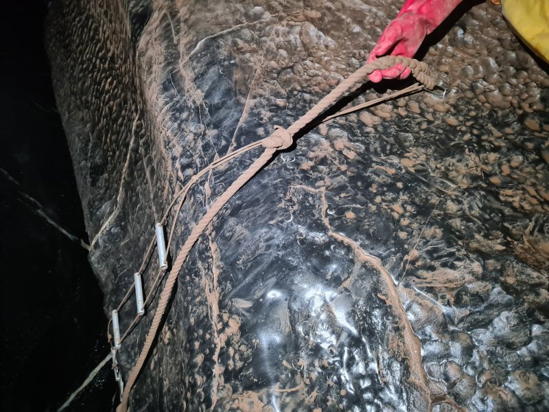
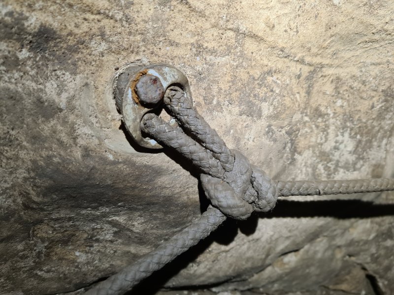
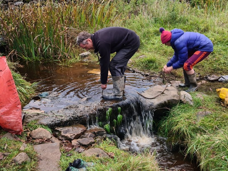
The American Society for Testing and Materials (ASTM International) published their standard for testing rope strength in 1983. The American National Fire Protection Association (NFPA) first published their rope standards in 1985. Dutch State Mines created Dyneema in 1989. The International Organization for Standardization published their standards for nylon and polyester ropes in 1990. The European rope standards for SRT rope and dynamic rope were created in 1997, but were subsequently changed to allow the use of thinner SRT rope for caving (because the standards for caving were made without initially consulting cavers), and actually came into force in 1998. The UIAA standards for dynamic rope were published in 1998, and subsequently followed the European standards starting from 2004. ASTM International published their standards for static rope in 2001, replacing their old rope testing standards. BlueWater produced their first all-polyester caving rope some time between 2000 and 2006. The UIAA standards for static rope were published in 2013. Hawser laid ropes continued to be occasionally used underground as fixed handlines, with some still in use at the time of writing in 2023.
This history section only covers ropes. This article also has a detailed history of many of the other devices and techniques that are used for vertical caving.
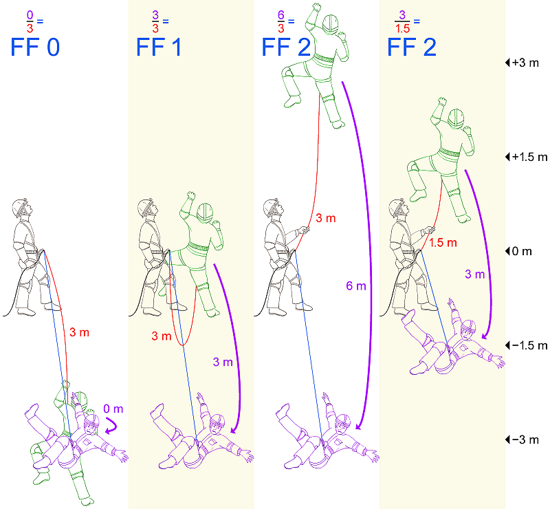
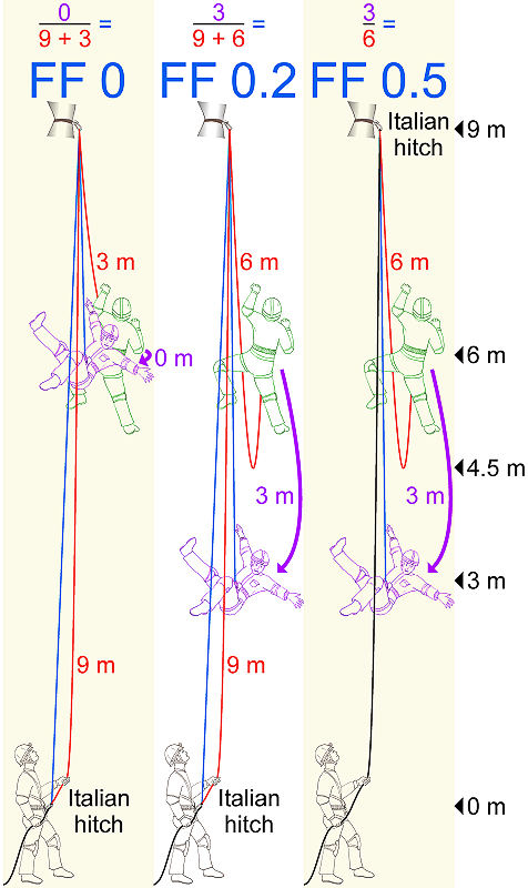
A measure of the shock load that a rope might experience, based on how far the fall was, onto what length of rope, calculated as fall_distance divided by rope_length, where fall_distance is the distance before the rope starts to stretch as it absorbs the shock. The actual distances are almost irrelevant to the shock load, only the ratio between them matters, since the rope's elasticity scales up at the same time as the fall distance. A person falling 2 metres onto a 2 metre length of rope (meaning that they fall from the same height as the rope's anchor) creates a fall factor 1 shock load. A person who climbs 2 metres above the same anchor, and then falls 4 metres onto a 2 metre length of rope creates a fall factor 2 shock load. European static ropes are not, in general, designed to cope with anything more than a fall factor 1 fall, and neither is the person experiencing them. A fall factor 1 fall with a static European rope can produce a shock load of 12 kN, which is near the limit of human endurance - a human could well be injured at 6 kN or less in a sit harness. This is why ropes are so heavily over-engineered, and why cavers (unlike climbers) try to avoid shock loading ropes. Dynamic ropes can absorb much more energy, producing a much lower shock load at the same fall factor. American static ropes typically produce higher shock loads at the same fall factors, as they can be far more static than European ones, so a fall on an American static rope is even more serious than with European static rope.
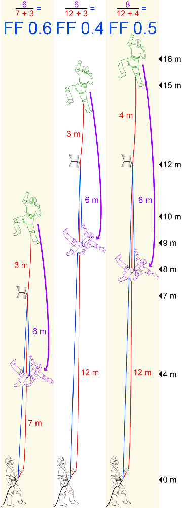
With rigging set up for SRT, the maximum fall factor that should ever be expected is 0.3, but the fall factors can be much higher for bottom roping. Several factors influence the fall factor in real cases, such as how many carabiners the rope passes through, and how easily it passes through them. These can make the rope act like it is shorter than it really is, increasing the fall factor. The rope length is only counted between the object that is falling, and the belay device that catches the fall. So for example, if a belayer at the pitch base is top roping a climber, using an Italian hitch located at the pitch head, then the fall factor relates to the length of rope between the Italian hitch and the climber, not the part between the belayer and the Italian hitch. Of course, it still relates to how far the climber falls, and with top roping, that is largely governed by how much slack is in the lifeline. The calculation gets very confused when the belayer gets pulled up into the air as they catch the climber, which often happens with belaying, or they intentonally jump into the air, which a good climbing belayer will. It also does not account for knots tightening and harnesses taking some of the impact, which softens smaller falls such as those below 1.5 metres.
Fall factors cannot represent falls which result in a severe swing, where the energy from the fall is converted into the swing without the shock load being applied to the rope. They can only help describe the severity of a fall where the rope has to absorb the shock directly. Fall factors relate only to systems with stretchy ropes. They do not apply to cables, chains or slings (especially Dyneema), which effectively have no stretch, and so can be treated as a rope with no length. In systems where there is no rope to stretch, the stretchiness of the object that is falling (such as the human or their harness) is the only part that can absorb the energy, so the distance fallen becomes the major consideration instead of the fall factor. This is because the actual force experienced is a product of the fall distance divided by the slowing down distance, and the fall factor is just a nice and easy way to work with that, when you have a stretchy rope. (This is also a simplification. It actually comes down to that popular physics expression f=ma, where a=dv/dt.) It does not realistically model what can actually happen with SRT, such as slipping off a ledge with a traverse line onto cows tails. It cannot cope with the mix of dynamic and static rope, the sit harness and the caver's own body movements, carabiners and hangers adding fall distance without shock absorbancy, the knots changing the shock absorbing nature of the rope, and most of all the traverse line heading in two directions, not directly away from the fall. Fall factors are only really useful when dealing with falls on a lifeline.
Where offcuts of rope are subjected to a series of shock loading tests. A drop test is different from a pull test, since pull tests slowly increase the force applied to a rope to work out what weight it can hold before it snaps. There is no shock loading in a pull test. Static/semi-static rope, when it is certified in Europe, is tested in accordance with CEN standard EN 1891. The standard differentiates between "type A" rope which is designed for caving and used for SRT, or an intentionally lower quality "type B" which is not designed for caving. In standard tests, the rope is loaded statically with 1529 kg or 15 kN (1223 kg or 12 kN for "type B") using figure of 8 on a bight knots for three minutes. A separate sample is loaded with a 100 kg weight (80 kg for "type B") using figure of 8 on a bight knots for a minute to allow the rope to stretch, then subjected to a fall factor 0.3 shock load without exceeding 6 kN impulse force (meaning that the rope should still have the right amount of elasticity), followed by 5 shock loads of fall factor 1 without snapping. With a separate sample, the extra amount that the rope stretches when a 50 kg load is increased to 150 kg must not exceed 5%, showing that it is static rope. (Static ropes certified in the USA use a completely different standard, such as NFPA 1983. This allows them to have almost no stretch - anywhere between 1% and 10% stretch at 10% of their specified minimum breaking strength - and almost no shock absorbing qualities. A popular American rope might stretch just 3% with a 400 kg load. The shock loading produced by drop testing or falling on these ropes can be extreme. American cavers may also use ropes certified to the voluntary standard UIAA 107, which is based on the European standards, or ASTM F2116-01, which is not based on anyone else's standard.)
The standard tests are carried out at a specific temperature and humidity. The ropes are tested when they are dry. When following standard tests with a new rope that is wet, it loses around 70% of its shock absorbing performance, and might only survive 2 or 3 fall factor 1 shock loads before snapping, when it would have survived 7 to 10 if it were dry. The wet rope will stretch around 10% more when absorbing a shock load, but can produce a shock load 10% higher than the same rope would have done when dry on the first shock load, increasing with each shock load to reach about 25% higher than the same dry rope by the fifth shock load. Wet ropes also bounce back far harder, and bouncing around after the initial catch of a fall can produce forces 65% higher than the same rope would have done while dry. If a rope is shock loaded while it is wet, it will be permanently damaged, so that even after drying, it will not return to its dry performance. Ropes that have been treated with a chemical treatment that stops the fibres absorbing water (known as "dry" ropes), might initially cope with more, but this benefit is lost if the rope is soaked for several hours (which is why there is no point in using "dry" treated ropes for caving). After slowly drying a rope which has not been shock loaded while wet, the rope regains its dry performance. Testing with ropes at high temperatures, such as 70°C or 80°C, reduces the rope's performance in a similar way to being wet.
Cavers who are testing their ropes often ignore the static load tests, and might use 80 kg for drop testing (presumed to be a representative weight for a person, but this excludes clothing and equipment). They then typically use the same set of drop tests as EN 1891 expected, and if the rope survives, they are then likely to continue with repeated tests at fall factor 1, or sometimes even increasing to fall factor 2, to see how many the rope will cope with before it snaps. It is common for a rope to survive numerous fall factor 1 tests when new, far exceeding 5 and sometimes approaching 40, and perhaps even a couple of fall factor 2 tests. However, an old rope that would still be considered usable might only survive 2 of the fall factor 1 tests. This testing can help to decide when to discard an old rope. The offcut that was tested must always be discarded, even if it did not snap during testing, as it might now be at the limit of its endurance.
It is worth noting that very few testing rigs owned by cavers follow the actual standard. For the test to be comparable with the standard tests, the drop distance is critical; while it might seem that the fall factor should be the same no matter how far it falls, the ratio of knotted rope to unknotted rope changes significantly at shorter lengths. Most caver setups are much smaller than they should be. For example, the British Caving Association's mobile testing rig can only test ropes at 80 cm long, instead of the standard 2 metres, and there is no facility for getting the environmental conditions right. Traditionally, it used wet rope (at whatever temperature it is outside), and an increasing fall factor instead of just fall factor 1, and this will dramatically alter how many tests the rope will survive. It does use the standard 100 kg weight. The results are still useful, but not directly comparable with the official standard.
Dynamic rope has the CEN EN 892 standard instead, or the international UIAA 101 equivalent. This is different for single ropes (normal rope used as a single strand), half ropes (also known as double ropes, thinner ropes used in pairs which do not share connections to anchors) and twin ropes (thinner ropes used in pairs which do share anchors). Single ropes are allowed a maximum of 10% static stretch with an 80 kg load, then must survive 5 fall factor 1.75 falls with an 80 kg load tied in figure of 8 on a bight with rope passing over a standardised lip, not exceeding 12 kN on the first fall, and a maximum 40% stretch on the first fall. Half ropes are allowed a maximum of 12% static stretch with an 80 kg load, then must survive 5 fall factor 1.75 falls with a 55 kg load tied in figure of 8 on a bight with rope passing over a standardised lip, not exceeding 8 kN on the first fall, and a maximum 40% stretch on the first fall. Twin ropes are allowed a maximum of 10% static stretch with an 80 kg load for a single rope, then a pair of ropes together must survive 12 fall factor 1.75 falls with an 80 kg load tied in figure of 8 on a bight with rope passing over a standardised lip, not exceeding 12 kN on the first fall, and a maximum 40% stretch on the first fall. I am not aware of any caver-owned rigs capable of testing dynamic ropes. In places where a half rope is used, one rope will be used primarily to catch a fall, while the other rope assists later during the catch, their dynamics are different from twin ropes, which are expected to catch a fall at the same time. Half ropes are not designed to be used as twin ropes, and will produce a higher shock load if used that way.
When ropes are stressed so much that they fail and break or snap, they almost always do so at the mouth of a knot, which often gets bluntly stated as "knots weaken a rope". That is not very helpful as a statement, because knots are essential to our use of ropes. Ropes are over-engineered to allow use of knots without the strength being reduced too far, and knots are carefully selected for their strength.
Nevertheless, over-stressed ropes normally break at the mouth of a knot. This is often said to be because of the tight bends that the knot passes around. It is true that bends do increase the stress, since one side is longer than the other, and the tensile stress from the load is concentrated on the outside of the bend, while in the unknotted parts of the rope, it is shared by the entire cross section of the rope. However, the stress on a bend is linear, along the length of the rope, the direction where it is strongest. This is why a rope rarely breaks on the big obvious bends of a knot. Instead, it normally breaks between two opposing small bends that have a relatively tight radius. Up then down, or left then right, which often happens just inside the mouth of a knot, such as a figure of 8 knot.
At that point, two things happen. Firstly, ropes are not a single unit, they are a braid of multiple fibres. The fibres that are loaded on one side of a rope around a bend, need to pass the load onto fibres that will now be loaded on the other side of the rope at the next bend. This happens due to friction of the fibres against each other, which relies on the braiding and compression from the sheath to bind them against each other, and this normally takes some distance. When the opposing bends happen in a very short distance, the load needs to pass from the fibres on one side of the rope to the other side very quickly, so the load has to pass across the rope via the sheath in addition to the cores (which are relatively linear). Secondly, the opposing bends appear to create a point on the rope where there is shear stress in addition to the linear stress created by the bends themselves. Shear stress acts across the rope, rather than along it, in the direction where it is weakest, similar to how scissors cut across paper. This happens at the same point as where the load passes from one side to the other. This makes it much more likely that the rope will start to split at that point. Because there is tensile stress at the same location on the outside of a bend, the splitting is likely to start on the outside edge of the bend just where it starts to transition into that bend from a location where it was under tensile or shear stress, and the load was switching sides of the rope. Once it starts to split, the tensile stress from the bend causes the split to rapidly propagate across that strand of rope, so the rope splits completely.
In some knots, there might be a two dimensional change in direction, which would create two different directions of shear stress, or a greater amount of shear stress, or torsional stress at the same point. These knots are therefore likely to be weaker than others. Knots where the bend direction remains very consistent throughout the knot while holding a relatively large radius, such as a double fisherman's knot, are likely to be much stronger, since they are dominated by bend stress, and shear stress is not a factor. They will still eventually split when the tensile stress on the outside of a bend is enough to split the rope on its own. Once the rope has passed some distance into the intertwined parts of the knot (after an initial bend), a lot of the tensile stress has been passed on to the other parts of the knot by friction between the rope strands. The individual strands are no longer under so much tensile stress, and any shear stress will also be reduced as a result, so there is less chance that it will break further into the knot. Therefore the rope is likely to break at the first tight bend or pair of opposing bends within the knot.
In knots tied on a bight, where the loop takes the load and one of the ropes emerging from the knot takes the load, the break almost always happens on the single rope's side, since it has the full amount of stress. The end with the loop also has stress, but shares it between two strands, so it is effectively halved. In drop testing, this means that unless there is a localised weak spot in the rope, the eventual failure of the rope will almost always happen just inside the mouth of the figure of 8 on a bight knot, on the side of the knot where a single strand carries the load. If the figure of 8 on a bight is tied in the way that makes it harder to untie after loading, with the loaded rope passing around the collar of the knot at the loop end, rather than the shoulders of the knot, the stress point appears a little closer to that bend of the knot, so the break might appear to be on the bend itself. However, the actual break normally starts at the point of shear stress immediately before the bend, rather than on the bend itself. Whichever way the knot is tied, once the rope snaps, the rope on the bend, which had been under a huge amount of tension, finally has the tension released, so it shortens and retracts part way back around the bend, so it might appear to have broken on the bend itself, but in actuality, it broke while that part of the rope was further around the knot, at the point of maximum shear stress immediately before the bend. See the stress diagrams in localization of breakage points in knotted strings, Piotr Pieranski et al 2001 New J. Phys. 3 10, to see where the breakage is most likely to happen. (I would appreciate confirmation of the shear stress presumption.)
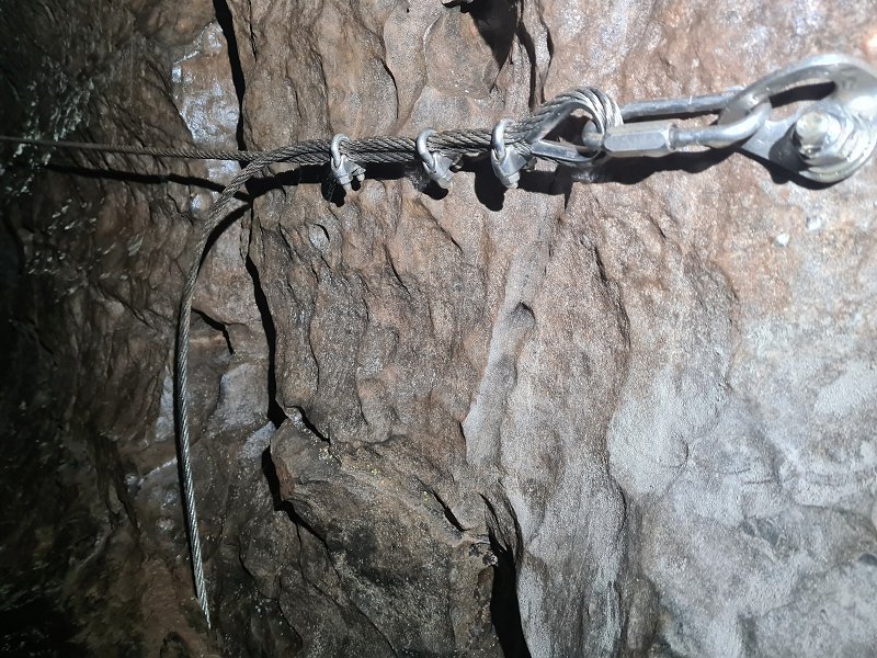
A rope made from strands of wire, typically steel or stainless steel. "Cable" generally refers to thicker cables, and "wire" generally refers to thinner cables, but either term can be used for any sized cable. Cable is much heavier than a rope of the same diameter, but it is also much stronger than a rope, and far more resistant to abrasion. The strength and weight depend on the material it is made from, but as a general rule, a stainless steel cable is about 2.2 times as strong as a nylon rope of the same diameter, but weighs 6 times as much. A very thin version is used to make electron ladders. Much thicker ones are too heavy to carry normally, but are sometimes installed as fixed aids, particularly as traverse lines for wire traverses. Because they do not have dynamic properties like a rope would, they can produce much higher forces if they are subjected to shock loads, so they are generally used in situations where shock loading is considered unlikely. They may be used in places where rub points could become a problem for ropes. Cables have historically been used for prusiking by Russian cavers, and winches would typically use cables rather than rope. Cables cannot have knots tied in them, so they rely on swaged eyelets, cable clamps and splices. Cables dramatically lose their strength when bent around sharp corners. A bend around a bar the same thickness as the cable can result in 50% of the strength being lost, and the loss increases exponentially for tighter bends. The distance it wraps around the bar is unimportant, and even a small deflection can cause the loss of strength if the radius of the bend is significant. As a result, loops or eyelets should have thimbles. Pulling on a cable directly using a carabiner is likely to reduce its strength by about half, depending on the thickness of the cable and carabiner, which negates most of the strength benefit from using cables.
Cables are made from a number of strands, where each strand is made up from a number of individual wires. The strands normally have a central core wire, with six wires twisted around it, so 7 wires in total. They can then optionally have another 12 wires wrapped around the outside of those, giving 19 wires in total. For low strength purposes, they may be used as a single strand like this, known as a 1×7 or 1×19 wire rope (sometimes written with a * or / instead of the × symbol). To make better cables, these may be used like a hawser laid rope, with three strands twisted together. However, it is more common for cables to have a central core strand with six similar strands twisted around it, known as a 7×7 wire rope or 7×19 wire rope, depending on how many wires are used per strand. Some manufacturers confusingly describe this as a 6×7 structure, while stating that it also has a wire core, which shows that the central strand is only there to hold the right shape, and is not load bearing. Thicker cables may then have 12 strands wound around the inner strands, known as a 19×7 or 19×19 wire rope, or they could have 6 much thicker strands wound around the inner strands, where they tend to be named only by taking the outer-most layer into account, such as 6×36 wire rope, ignoring the 7×7 inner structure. Other structures are possible, but these are the most common.
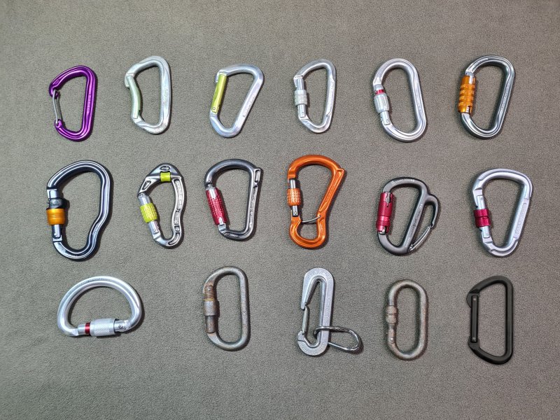
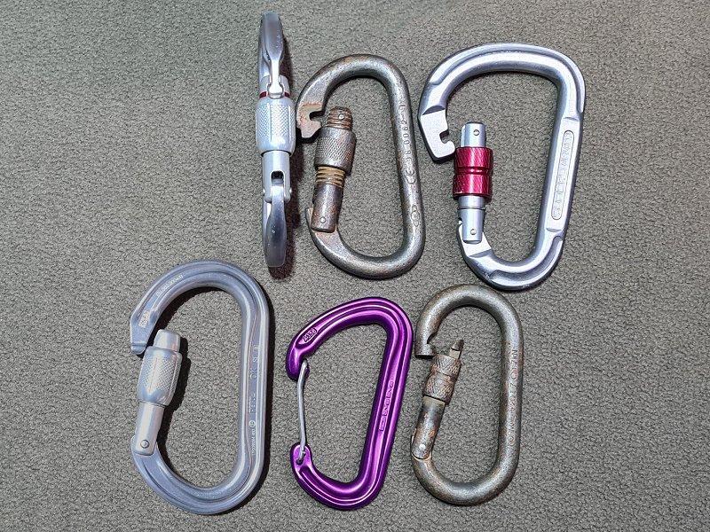
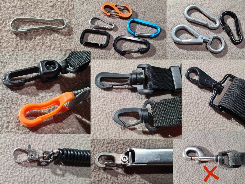
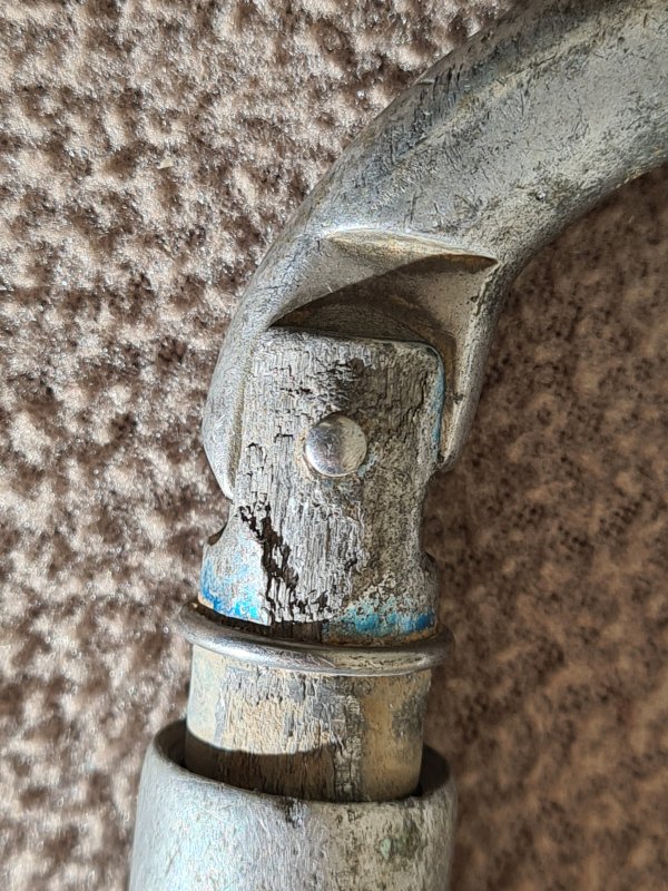
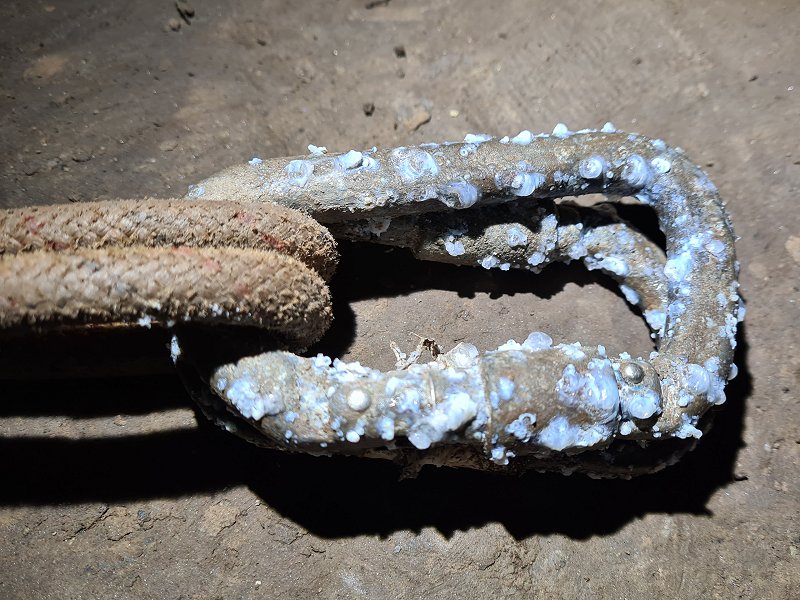
Metal links that are a bit bulky but relatively easy to attach/remove from ropes or other metalwork. Used to attach ropes and ladders to anchors, and various pieces of SRT gear to each other. General purpose items that are used in many different situations. Fundamentally, a carabiner is a hook, with a hinged gate on one side to open/close, which closes automatically using a spring, preventing loads from accidentally slipping off the hook. In the vast majority of cases, the gate hinges inwards into the body of the carabiner, but there are some designs where it hinges outwards. This intentionally makes it easier to clip things into a carabiner, than to remove them from it. (If the gate opens outwards, then if the load somehow ends up pulling in the wrong direction onto the gate, it would pull the gate open, rather than closed, so these types are not suitable for caving.) In most designs, the spring is separate from the gate, and normally hidden inside the gate, but there are some designs (such as wiregates) where the gate itself acts as a spring. In the majority of designs, the gate has a standard hinge joint, but in some designs, the spring itself acts as a hinge, and there is no hinge joint (particularly very weak designs made from a single piece of metal or plastic, sometimes found on dog leads or luggage straps). During normal use, the load is positioned on the stronger parts of the hook, not the gate. In all good designs, the gate itself provides some of the strength, with a load bearing latch.
Loads of shapes, but the normal ones are "oval" (actually a straight sided oval, with straight sides and half-circle curves at each end like a capsule or running track, which are better for holding some tyes of pulley), "offset oval" (where the curves on the gate side are more gentle than on the backbone side), "D-shaped" (with sharper corners on the backbone side, and the same size at each end, quite uncommon), "offset D-shaped" (with sharper corners on the backbone side, slightly wider at one end than the other, the most common design), D-ring, "pear-shaped" (like a slice of pizza with the corners curved) and "HMS". HMS is the same as pear-shaped, but slightly bigger so that an Italian hitch can change direction more easily. "Gourd-shaped" carabiners (between a figure of 8 shape and pear-shape, with a wide end, a narrow end, and a narrower waist) are very common for utility purposes, but are almost never used with caving, though they are sometimes sold for holding a belay device. Some may have odd shapes to work better with pulleys or cables.
The gate may be "locking" or "snap-link"/"snap-gate" (non-locking). Locking types may be "screw gate" (which do not auto-lock themselves), "twist" (which auto-lock) or have some other mechanism that must be pushed out of the way to open them. Screw gates, when hanging vertically, are normally oriented with the screw gate locking downwards, so that gravity helps keep them locked, with the mnemonic "screw down so you don't screw up". (There are some very specific cases where this is not done, such as when using power tools, since powerful vibrations cause them to move in the opposite direction from what gravity would normally suggest. This exception is not normally relevant to caving.) Auto-locking gates are harder to clip onto things, because they normally need fingers to hold the gate open without getting in the way, but they are immediately locked once the gate is released, which can be safer in many cases. Twist locks can be double, triple or quadruple action (or perhaps higher), requiring more movements to open them, which makes them harder to use, but less likely to accidentally open. Snap-link gates may be "straight" (easier to clip into hangers), "bent" (easier to clip into ropes and a slightly wider opening) or lighter weight "wiregate" (close much faster if they pop open or "flutter" if hit into a surface hard during climbing falls, not important for caving). "Twin" or "double" gate designs have two gates, one opening inwards and one opening outwards with opposite hinge ends instead of a lock, and can be opened by something poking between the gates. The gate normally latches closed with either a nose hook and pin (which snags everything) or "keylock" shape (anti-snag), but "dovetails" (also known as "cross-type", "toothed" or "hook and seat", which snag everything even worse) were previously common. Several designs, each with different names, provide the anti-snag feature with wiregate carabiners. Carabiners without a load bearing latch for their gate have a far lower strength rating, and are not normally used for caving.
Some designs have built in pulleys for running them along steel cables. Some have braking carabiner slots built in. Some have dividers to keep ropes captive at one end of the carabiner or the other, known as a "captive eye" or "captive carabiner". These may have a separate gate for the captive eye. "S-carabiners" take this to an extreme, with an S-shaped body, and opposing gates at each end, but these are almost never strong enough to be used for caving. Some have odd shapes to stop equipment from sliding easily to the wrong end, partcularly ones intended for use with belay devices. Carabiners are typically made from aluminium which is light weight but abrades faster, or steel which is heavier but resists abrasion much better (and generally visibly bends before it fails, which can be a helpful warning at very high loads). Aluminium and steel corrode when exposed to water for lengthy periods. Some are made from stainless steel, which resists corrosion (but often does not bend before failing at high loads). Some are made from titanium, but it is not easy to forge without potential defects, and so most manufacturers do not wish to work with it. They may be made from metal with a round cross section, or an I-beam shaped cross section, or some other weight relieved cross section. This cross section is known as their "stock". Round allows ropes to slide a little more easily over them, perhaps useful for belaying. I-beam and other weight relieved cross sections make the carabiner lighter without initially affecting the strength, but because there is less material, they can wear through more quickly when muddy ropes slide through them a lot, though this is not much of a problem with steel carabiners.
Carabiners are normally designed only to be pulled in two directions at once, directly opposite each other, along the length of the carabiner. It is common to clip a carabiner into two ends of a sling which is looped around a natural, with a rope pulling on the other end of the carabiner, and as long as the two ends of the sling approach the carabiner from a similar direction, this is considered acceptable. However, if they approach the carabiner from very different directions, this puts a three directional pull on the carabiner. Most carabiners are not actually designed to be pulled in that way, and this can reduce their strength significantly. D-ring carabiners are one exception to this, as they can be loaded in a range of directions over 180°. Oval carabiners can often cope with a fairly significant three directional pull without a significant loss of strength, but this depends on how far apart the pull directions are. With other common designs of carabiner, the sling can easily end up pulling on the gate, which reduces the strength to the same as if the carabiner were loaded sideways. If the three directions are very far apart, it can experience a much higher force on the gate than the load that it is holding (just like a Tyrolean traverse), so it can fail at surprisingly low loads. In such cases, having the sling ends at the hinge end of the carabiner normally allows it to cope with significantly more load than if they are at the nose end of the carabiner, but it is much better to use a more appropriate design of carabiner that is designed to be loaded in three directions.
Some designs of carabiner exist for rigid webbing, commonly seen in paragliding equipment. These have square shaped or flat ends, and while these may look better for using with slings, they do not work well with the flexible webbing used for most slings. In use, the sling slips to one side of the flat surface, and pulls much harder on the gate side of the carabiner. They are not designed to be loaded that way, and will fail at much lower loads than they are rated for. These carabiners can only be used with very specifically made webbing designed to be rigid, with exactly the right widths, and should not be used for standard slings. As a result, these carabiners are not generally suitable for caving purposes.
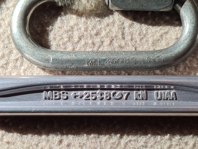
PPE rating for the minimum breaking strength (MBS) of carabiners is 20 kN in most cases in Europe and 22 kN (actually 5000 lb) in the USA, but the European standard EN 12275 requires 18 kN or 25 kN for some designs. As a result, most carabiners can hold 2.2 tonnes or more (actually given as a breaking strain of 22 kN) when loaded correctly, or 0.7 tonnes when loaded incorrectly, such as sideways, or with the gate open. Carabiners usually have the ratings for loading in the correct direction, loading sideways, and loading in the correct direction with the gate open, stamped onto the carabiner itself. 2.2 tonnes is the weight of two small 5-door 5-seater family cars, or 4'279'174 baked beans. Thick steel carabiners might be able to hold 4.5 tonnes, just in case you ever needed to hang a Red Arrows hawk off the wall of a cave. There are some extreme models that go as high as 7.1 tonnes, enough to hold an entire double-decker bus worth of passengers, an 89 cm sphere of gold, or about 65'000'000 worker bees, assuming they have not gone extinct by the time you read this. These ratings apply to new carabiners, not ones that have been abraded, scratched and battered through years of use, or corroded by exposure to water. While there are many lower quality carabiners produced for a wide variety of purposes, including dog clips, keyrings, camping equipment and novelty toys, these should never be used for caving. There is a chance they could be mistaken for a PPE rated carabiner, and used in a situation where reliable strength is essential, and they are unlikely to cope with the rigours of caving anyway. They are sometimes included when purchasing equipment online that claims to be PPE rated, such as multi-purpose ropes. In such cases, the carabiners absolutely must not be trusted (and the other product's PPE rating should be considered either fake, or highly suspect, if it is being sold with non-PPE carabiners). If a carabiner does not have the correct ratings properly stamped into its metal, it is likely to be fake, and must not be trusted.
In case you are wondering about which spelling to use, "carabiner" is the dominant spelling but "karabiner" is valid. The original word is German, where it is commonly spelled "Karabinerhaken", meaning a "carbine hook", a hook for a type of rifle. However, even in German, it was originally spelled "Carabinerhaken", and the "k" is a relatively recent change, with the older spelling still remaining in current use in southern Germany, Austria and Switzerland. This got shortened to just the name of the rifle. The name of the rifle is spelled "Karabiner" or "Carabiner" in German (with "Carabiner" being the original spelling), "carabine" in French and "carbine" in English. The word originates in French, not German. The name of the soldiers who used them is "Karabiniers" or "Carabiniers" in German, "carabinier" in French, and either "carabineer" or "carabinier" English. The metal link was used by British cavalry carabiniers for centuries, and already had 4 English names before anybody decided to use the German one. The name of the metal link is "Karabinerhaken", "Carabinerhaken", "Karabiner" or "Carabiner" in German and "mousqueton" in French (meaning "for a musket"). Spanish and Italian, rather unsurprisingly, follow the French spellings in all cases, changing only the word endings according to the rules of each language. Dutch follows German, with "karabijnhaak". So it really does depend on whether you like to use the original French name for a type of rifle, the Germanised spelling for the rifle, the Anglicanised spelling for the rifle (or the Hispanised or Italianised, for that matter). With English being a Germanic language with very heavy Romance (French and Latin) influence in the spellings of more than half of its words, there could be arguments for both. English is three times more likely to use a "c" at that position in a word, just as it is with the name of the rifle and the soldiers who used them, and how you don't drive a "kar", or use batteries containing "kobalt", or call the animal a "kat" (even though the word "cobalt" also comes from German, where it is spelled with a "k", and "cat" is also Germanic, which German spells with a "k"). However, some people like to use a "k" to make it feel extra German, just like the "ö" in the British band "Motörhead", and the distinctly German sounding Berghaus, and Möben Kitchens, which are both British companies. German makes some people assume that outdoor equipment will be engineered better for outdoorsy purposes, apparently. If that was confusing, just read the first sentence of this paragraph again. Oh, and it's easier to make jokes about how "[someone] has crabs" if you use a "c".
Incidentally, it is not known how the rifle got its name, but it might be the Latin name for the scarab beetle, "scarabaeus", which comes from the Ancient Greek "κάραβος" meaning "beetle". Other words with that origin include "crab" (rather appropriately), "crayfish" and "scorpion", just in case you needed more evidence that a "c" was more appropriate. Those might come from the Arabic "عَقْرَب" meaning "scorpion", "قَارِب" meaning "to approach" or "خَرَبَ" meaning "to ruin".
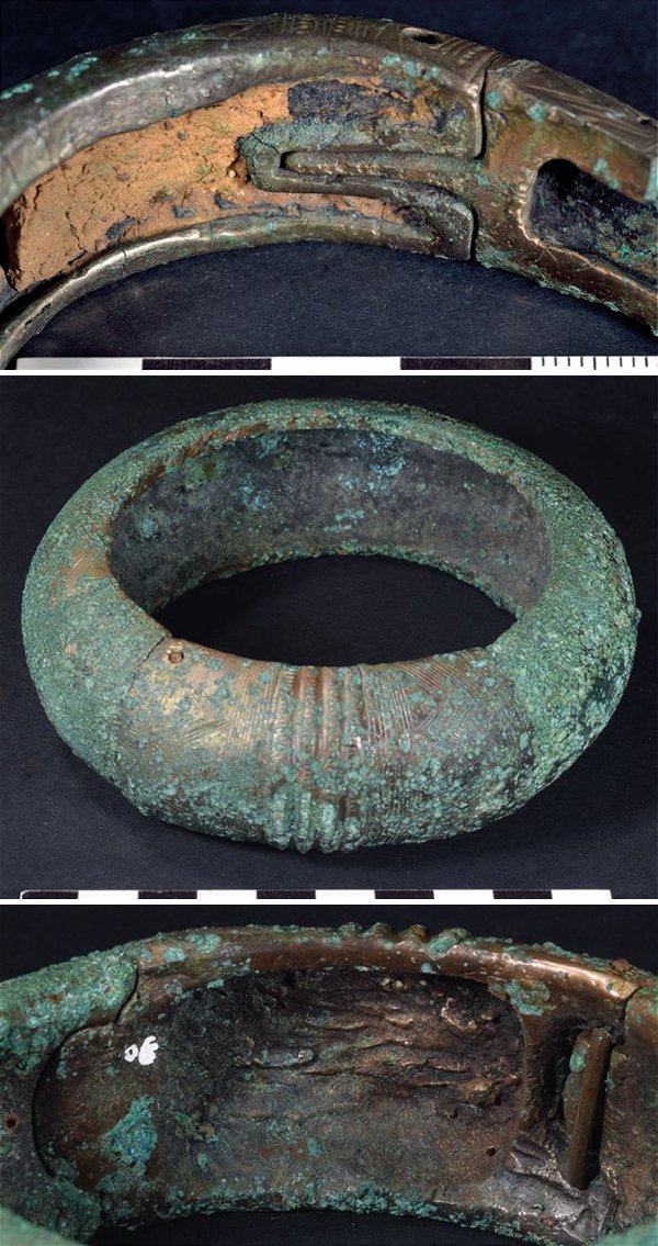
Pinned mortice and tenon joints (how carabiner gates are connected) first appeared in wood, with the earliest known example dating from 5099 BCE in what is now Germany, used for lining a well. The specific pin technique used there may be known as a tusk joint or tusk tenon in modern woodworking, where the pin passes only through the tenon, and is slightly different from a carabiner hinge, where the pin passes through both the mortice and tenon. Bronze bangles (bracelets) were made in Brittany, France in 1450-1300 BCE, which have a hinged gate with a mortice and tenon latch, held closed with a pin. They did not spring closed, and the shape would allow loads to rest on the relatively weak gate, but they are otherwise impressively similar to a modern carabiner. Other designs relied only on pinned mortice and tenon latches. They were presumably created by the Armorican Tumulus people. This incredible find was reported in "Nordez, M. (2023). Metal hoards in a ritual space? The Atlantic Middle Bronze Age site of Kerouarn, Prat (Côtes-d'Armor, France)". This approach had spread to Austria, Switzerland and Britain by 400-200 BCE. Fibulae brooches that worked almost identically to a safety pin, had appeared as early as 1400 BCE in Mycenaean Greece, and designs are still used today. Unlike a carabiner, the spring tries to open the gate, and it needs to be manually closed. Greek earrings from 400-200 BCE and better versions from 200-1 BCE used the same approach. Roman padlocks had large locks that had to be manually assembled to close them, rather than the hinge and spring of a carabiner gate. Rings almost identical to the non-hinged Brittany bangles, which may have been slave shackles, and almost exactly match modern bull nose rings, were also identified as Roman, but their origin and age is unknown. Neither half of the ring could be used without the other, unlike a carabiner's hook and separate gate. Lombard earrings from around 750 CE used the same principle as the safety pin, in Cividale del Friuli in northern Italy. Oval links that look almost exactly like an oval carabiner, were in use by the Landshut Armoury in 1485, in Bavaria-Landshut, Holy Roman Empire, now Germany, depicted in the Zeughausinventar von Landshut by armory master builder Ulrich Pesnitzer. These had a removable mortice and tenon gate, presumably using pins at each end instead of a hinge and latch, and could function as a hook without the gate. These were used as a removable link which could be connected to a rope, just like a modern carabiner. They almost certainly did not have a sprung gate, so they would not normally be considered to be a carabiner, and were called "hagken", an older spelling meaning "hook". The Landshut Armoury also had gourd-shaped solid chain links, which could be used to attach a chain to a rope or other objects, and were used to connect them to parts of a horse-drawn gun carriage. Similar chain links had been used during Roman times.
The metal clips that were the original carabiners, were first depicted by aristocrat Martin Löffelholz von Kolberg in about 1505 in the Löffelholtz-Codex, with a sprung gate made from the spring itself, without a load bearing latch, very similar to the fibulae brooches. They were shown as part of a bridle/muzzle for horses, where they were riveted directly to the leather (a design that remains in use today). They were also depicted as a way to connect reins to a horse's bit, using a snap hook design with a captive eye which a strap could be attached to. Both designs were used in the Nürnberg (Nuremberg) region of the Holy Roman Empire, now Bavaria, Germany, and were referred to as a "hack", meaning "hook". German artist Albrecht Dürer, who painted knights, horses and their equipment extensively in the Nürnberg region at the same time, apparently did not paint anything similar, suggesting that the carabiners were something very uncommon, and are likely to have been a new invention.
Swivel joints are rarely used for caving carabiners, but they were of great importance for early carabiners, and are still seen in many carabiners used for industrial purposes, and for less demanding uses such as bag straps. The swivel joint itself had developed as the axle of a potter's wheel, which appeared in Mesopotamia (now Iraq) around 4200-4000 BCE. For metalwork, it can be found in Egyptian rings from 1991-1802 BCE. Swivel joints had appeared in the connection between a horse's bit and its cheek pieces around 900-800 BCE in Luristan (now Iran), an approach that reached Villanovan/Etruscan Italy as early as 800-700 BCE, and then spread to Greece and what is now Germany. Ancient Greeks and Romans used swivel joints with a limited range of motion in door hinges, from as early as 800-400 BCE. Well developed swivel joints were commonly used as parts of Roman manacle shackles throughout central Europe during the Roman Empire, starting from 100 BCE, with a few examples from eastern France, a couple from northern Germany and at least one from northern Italy. They were used to connect chain rings in Britain around 43-410 CE, and are thought to be Roman in origin. Swivel hooks have been found dating from Medieval Britain (after the end of the Roman occupation) and other parts of Medieval Europe, and while the exact date or location of their origin is not known, a well dated German example is from 1250. Swivel hooks might be used to hang pots above a fire. Swivel joints can also be seen in the connection between a horse's reins and bit shank in curb bits from 1325-1350 in Napoli, now Italy, an approach which spread throughout Germany and France, and can be seen in numerous other examples.
The metal clips were then adapted as a way to hold cavalry weaponry, and the specific device that gave carabiners their name was used to clip a carbine rifle to the leather shoulder strap of cavalry carabiniers. While they are usually stated as having their origins in the Napoleonic Wars, they had in fact existed for at least another two centuries before then in parts of Holy Roman Empire that are now northern Italy, Spanish Netherlands (now Belgium), the Dutch Republic, Britain, Sweden and Austria, as well as the parts of the Holy Roman Empire that subsequently became Prussia and Germany. They were originally known as a "swivel" in English (spelled "swivell" in the 17th century), since they formed part of a swivelling connection to the shoulder strap, and were presumably developed as an adaptation of a swivelling hook. Swivel carabiners for weaponry are now often called a "spring clip" by historians. Graeme Rimer, former curator of the British Royal Armouries stated (personal correspondence) that swivel carabiners are likely to have first appeared in Britain around 1600 at the earliest, but that the exact date is not known. At that time, they would have been used with an arquebus (a longer version of a carbine), by a harquebusier. In particular, it was the cavalry that would use them, since the spring loaded gates would not pop open from the movement of a horse. The vast majority had a separate flat spring instead of the gate being made from the spring, and this required them to have a teardrop shape, so that the spring could have something to push against. Their original use with horse tack had already been largely replaced with buckles. I have tried to work out how their usage spread through Europe.
(The shoulder strap was originally known as a "swivel belt" and later "carbine sling" or "baldric" in Britain, "Karabiner-Bandelier" in German, "banderole porte-mousqueton" or "baudrier" in French, and "armacolo", "tracolla", "bandolera", "bandoliera" or "balteo" in Italian. In modern wording, "bandolier" holds amunition and gunpowder, while a "baldric" holds a weapon, but originally, either word could be used for either purpose. "Baldric/baudrier" just means belted-on, originally referring to a sword. "Bandoulière" was first recorded in French in 1586, for holding a sword, originating in Catalan as either a small strap or item used by a band of men. "Belt/balteo" is a belt for holding a weapon, which could also mean a waist belt. "Armacolo" means weapon-collar, and "tracolla" means across-collar. Apart from two English terms, these all originally related to carrying swords, so the existence of the term does not help to work out when it was first used with a carabiner to connect to a rifle/arquebus.)
A historical record desribes how in 1566, cavalry from the Duchy of Ferrara, part of the Holy Roman Empire, now in northern Italy, may well have been using carabiners. The description says that troops were sent to Hungary via Austria for a war against the Turks, an event for which Duke Alfonso II d'Este had gone to great lengths to show the finest military uniforms and equipment. Harquebusiers had a large arquebus on their saddle, and a smaller arquebus hung on a shoulder strap for weapons ("ad armacolo"), hanging below their right arm just above the hip. The text is very clear about the positioning, which exactly matches how later shoulder straps were depicted ("un archibugietto ad armacolo che gli pendea sotto il braccio destro sul fianco", meaning "an arquebus small in the configuration of weapon shoulder strap which to him was hanging freely like a pendulum beneath his upper arm right-side next to flank"). It does not mention carabiners specifically, and they could have been tied on, or held with a simple hook. However, even if carabiners were not used at that point, this is the earliest known mention of using a shoulder strap to hold an arquebus, and will have been the inspiration for carabiners to be used for that purpose. It seems highly likely to have originated in what is now northern Italy, just over the Alps from where the earlier horse tack carabiners had been used. 40 years later, the northern Italians then seem to have been responsible for spreading the idea of carabiners to Belgium and The Netherlands, where they were then seen by German mercenaries, and adopted back into the German military with their new purpose. (Shoulder straps had previously been used in Akkadia, now Iraq, in 2400-2200 BCE and ancient Egypt around 2030 BCE to hold quivers of arrows. The ancient Greeks had a φαρέτρα/pharétra quiver and a τελαμών/telamon strap to hold a shield or sword. Ancient Romans also had a balteus shoulder strap to hold a sword's scabbard from around 100 CE.)
Captive eye carabiners appear to be depicted, along with separate swivel joints that they clipped into, in the connection between a horse's curb bit shank and reins in the 1570 German translation of Gli Ordini Di Cavalcare, known affectionately as Ippokomikē or Hippokomikē. The original Italian version was written by Federigo Grisone in Napoli (Naples), Kingdom of Naples (now Italy), during the Italian Renaissance, but the Italian versions of the book, which were published repeatedly with illustrations from 1550 to 1590, never showed those designs. The two designs with carabiners are only included in the German version translated by Johann Fayser from München in the Holy Roman Empire, now southern Germany, whose illustrator is not known. (The woodcuts for printing may have been carved by Swiss Jost Amman, who later used the illustrations in his own publication.) Whoever originally drew the German version is very likely to have been from the München area too, and the designs are very much in the ornate German style. The depiction of carabiners with horse tack is unsurprising, as it is quite close to where Martin Löffelholz von Kolberg had drawn the earlier carabiners. The carabiners shown are long and thin, with a rounded main body, and a gate made from the spring itself. The same book also shows an alternative version using a shackle instead of a carabiner, but most of the 16 designs showed basic hooks or forged rings, suggesting that carabiners were still relatively uncommon. (Shackles can be seen in curb bit designs from the Holy Roman Empire, now southern Germany and eastern Germany, from 1600-1650.) I could not find any surviving examples of early carabiners from horse tack in any museum collections, despite a very large number of curb bits, snaffle bits, muzzles and associated horse armour surviving from that era, so they are unlikely to have been in common use.
The first time carabiners for holding weaponry are thought to have been depicted is in a series of paintings by Flemish artist Sebastiaen Vrancx, between 1601 and 1615. They are shown as being used by cavalry harquebusiers on both the Flemish (now Belgium), and Dutch Republic (now Netherlands) sides of a series of battles. At the time, the Flemish side was part of the large territory owned by Habsburg Spain called Spanish Netherlands, and the Dutch Republic was still trying to break free from it. However, even though the Spanish infantry fought alongside the Flemish militia, a Spanish book about military tactics published just two years earlier makes no mention of carabiners, and instead describes how an arquebus needed to be held in the hands while on horseback. As a result, they seem not to have been used within Spain at that time. Two of the paintings were made between 1601 and 1615, one of which depicted the siege of Oostende (Ostend) that took place in 1601-1604, and one was made before 1610. As with many of his later paintings, the existence of the carabiners is implied in two of them only by the arquebus being slung behind the back on a shoulder strap, in an arrangement that would have needed some kind of attachment. However, one of the 1601-1615 paintings clearly shows a carabiner on a Dutch Republic harquebusier, though the details are hard to see, and the arquebus is not clipped to it. It is clearly fixed to each end of the shoulder strap, and could not slide up it. It is not clear enough to see if it had a swivel connection, but it probably did, given its similarity to later designs. It is distinctively circular. At that time, the Dutch Republic had only just stopped being an English Protectorate, but the design is quite different from most of the British ones. In all paintings, only one or two harquebusiers have shoulder straps, and most resort to holding the arquebus in their hands, suggesting that carabiners were expensive or relatively new, and only a lucky few were able to use them. It is quite possible that mercenaries hired from the Holy Roman Empire originally had them, which would explain their low numbers, and would also explain how the idea got from the Holy Roman Empire into Flanders and the Dutch Republic. However, it is far more likely that the idea came from northern Italy, since many Italians were being brought over to serve on the Habsburg Spanish side there, and they seem to have already had carabiners. It was only later that Sebastiaen Vrancx would serve as a captain for the Antwerp civil militia, but his incredibly detailed earlier paintings had clearly been taken from direct observation of the local military, and he had presumably travelled to see the siege of Oostende in person as a tourist, like many other people. It is not known whether he had directly seen the equipment of the Dutch side, and he may have just assumed they used the same equipment as the Flemish and Italian side.
There is very little further known evidence to help work out when they started to be used in that region, or its surroundings. Other artists did not seem to notice them, even when depicting military equipment in the areas where they were being used. The Riding School or Exercise of Cavalry, a collection of prints by Jacob de Gheyn II from the Dutch Republic in 1599 showed harquebusiers without swivel carabiners. Wapenhandelinghe van Roers Musquetten ende Spiessen, a detailed book by the same author in 1607, showed a series of military drills, but did not show cavalry or any swivel carabiners. They were not shown in the 1529-1579 editions of Catalogus Gloriae Mundi by Barthélemy de Chasseneuz. They were also not shown in Jost Amman's illustrations of harquebusiers, such as the 1596 Kriegßbuch volume 1 and 2, which were published in the Holy Roman Empire, not far from where the earlier horse tack carabiners had been recorded. This particular fact suggests that the southern Germans had not developed the use of a shoulder sling to hold a musket or arquebus. In general, all these early mentions and depictions of arquebuses, showed that they were held in the hand, or resting on the shoulder, or supported by infantry using a shooting stick.
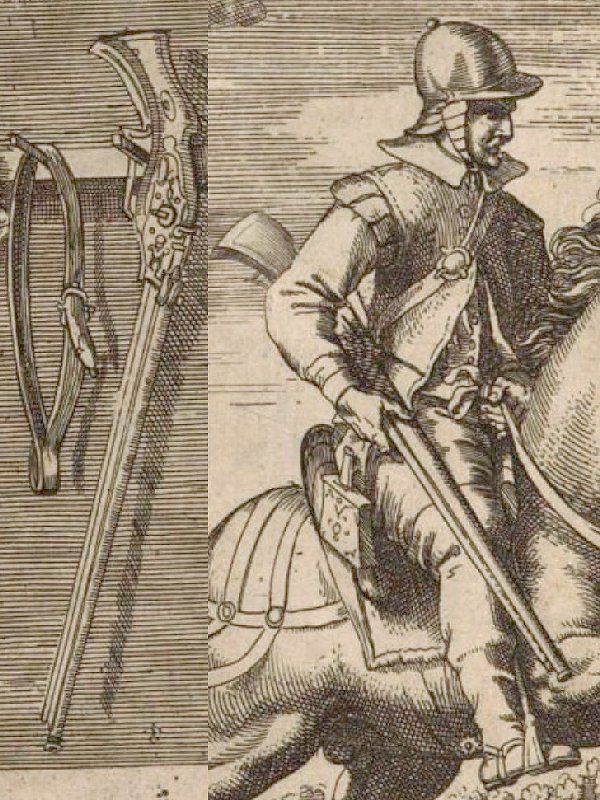
Two Italian language books, both written by Italian officers and published in the Spanish Netherlands, now Belgium, help to shed some light on the beginnings of their use in the Netherlands, though the differences between them may have simply been due to the authors being from different places. Both officers were serving the Habsburg Spanish in the Spanish Netherlands, and their books were published just one year apart. In 1610, a military instruction manual written by Lelio Brancacci, an officer from Napoli, Habsburg Spain (now southern Italy), failed to mention carabiners, in spite of describing the shoulder straps ("tracolla") of infantry harquebusiers being used only to carry ammunition, and in spite of describing military tactics of cavalry harquebusiers. It only described arquebuses being supported by infantry using a shooting stick. However, in 1611, another Italian military instruction manual written by Lodovico Melzo, a knight from the Duchy of Milan (now northern Italy) which shared a border with the Duchy of Ferrara, showed the uniform of a harquebusier and described how an arquebus was carried using a shoulder strap, written without further detail as being "carried [...] with the bandolier". The illustration showed only what looks like a fabric loop in the shoulder strap which appears to be looped over part of the arquebus, and did not clearly show a carabiner, but this is likely to be a mistake by the illustrator, who would not have known what they were depicting. The captain, meanwhile, held his arquebus in a holster, using the word "fonda", which referred to the enormous leather holsters used to carry large pistols. (In 1613 in Flanders, now Belgium, servants protecting a Flemish nobleman travelled with an "arquebuse en bandoulière", suggesting the use of a shoulder strap and perhaps a carabiner. However, this French term is also confusingly used to refer to holding the butt of the rifle in one hand, and leaning the barrel on the same or opposite shoulder. The servants were probably using this approach. This is how Ottoman troops were depicted carrying theirs in 1539, described using that same French term in 1559 with Slavic troops, and how many European nations did in subsequent years. Even when the Ottoman soldiers did use a strap in the 1700s, it was attached at two points along the barrel, like a modern rifle strap, without using a carabiner.)
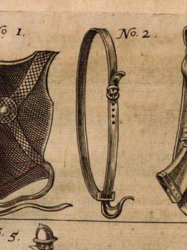
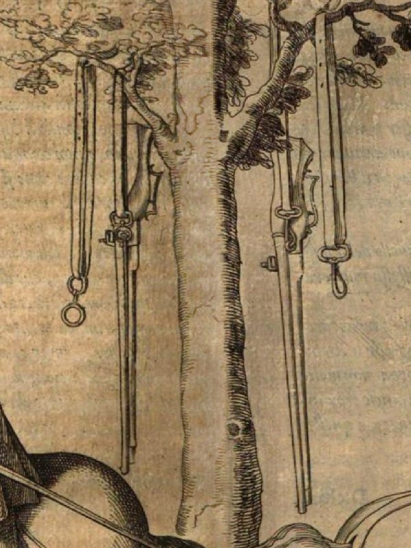
The earliest known definitive mention of carabiners for holding weaponry is from 1616 in Kriegskunst zu Pferdt by Johann Jacob von Wallhausen, in what was then the Holy Roman Empire, later Prussia, now Germany. What have the Romans ever done for us? (It should be noted that the Holy Roman Empire was not actually very holy, it was not Roman in any way, and it did not operate like a normal empire.) The diagrams look a little badly drawn, and are depicted and described without a swivel joint, but the description clearly talks about a sprung gate. (His books were known to have numerous publishing errors from being rushed to print too quickly, and illustration mistakes are hardly a surprise.) If they did not have a swivel, then they will have been captive eye carabiners instead. Either way, they were described as if they were something relatively new for that region. In 1617, Flaminio della Croce, yet another military captain from Milan, serving in the Spanish Netherlands, wrote a book which clearly depicted swivel carabiners. They were used to hold muskets and arquebuses, used by both harquebusiers and "free musketeers" - paid mercenaries from their own territories (the word "franco" makes it look French, but in Italian, the same word can instead mean being free of military responsibility, which is how it is used in that book). The carabiners are simply called "ferro", meaning "iron". One carabiner has a clearly circular design, exactly like the one painted by Sebastiaen Vrancx, but with a standard captive eye after the swivel joint, that could slide up the shoulder strap. The details of the carabiner's gate are not shown, and it is depicted as just a ring, but the illustration shows it being removed from the musket in order to reload, which would not be possible with a simple ring, so it must have had a gate. The other one was clearly depicted as just a hook, without a gate, where the end of the hook bends over far enough that it is less likely to accidentally fall off. Both designs have swivels. The book also shows a plain ring that was permanently attached to both the arquebus and the shoulder strap instead of a carabiner, which was said to be a terrible idea even though it could never unhook accidentally, because it could not be removed in an emergency, such as when trying to rush away from a falling horse. While the book talks in detail about new military roles and new ways to do things, it talks only very briefly about the carabiners, as if the Italian military readers will already be well aware what they are and how they work, and mentions old conversations about them. Several designs were in use, so they were clearly well established within the northern Italian cavalry.
Swivel carabiners were clearly depicted with a sprung gate and swivel connection in the Dutch Republic in 1624. The distinctively shaped design is quite similar to the one depicted by Sebastiaen Vrancx, but could slide up the shoulder strap, like the one depicted by Flaminio della Croce. It is slightly more teardrop shaped, and not perfectly round. They are depicted in Swedish uniforms from when they took part in a battle during the Thirty Years War in 1631, and they may have had them prior to that. The design has a sprung gate and swivel connection. Mercenaries from the Holy Roman Empire (described as German) who fought for Sweden during the Thirty Years War are also depicted with the same design. They were not depicted as being used by the French cavalry of that era. Swivel carabiners were mentioned in British cavalry instructions by John Cruso in 1632 and depicted in illustrations that accompanied that publication. They were described only as a "swivell" that was attached to a belt, as if they were something already considered normal.
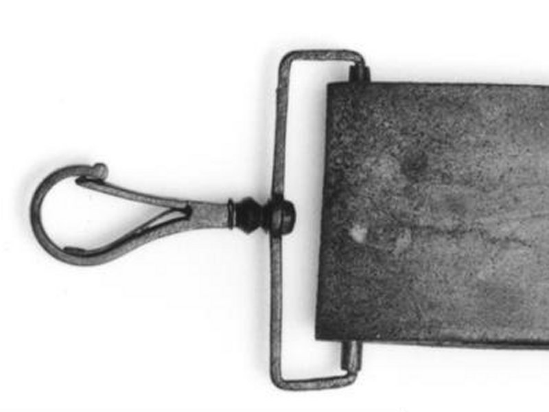
The earliest surviving examples of British carabiners, which are also the oldest known surviving carabiners of any kind, date from 1640 (British Royal Armouries Collection, XIII.298), at which point they were in common use with the British cavalry. They appear to be the design depicted by John Cruso, being teardrop/pear-shaped with a swivel connection. They had a sprung gate, but did not have a load bearing latch. Some had a notch that caused the gate to align correctly from side to side (two different designs can be seen in Littlecote The English Civil War Armoury, Thom Richardson and Graeme Rimer, 2020). The same designs were used in 1650, at the end of the English Civil War. Virtually identical designs are still in use today on handbag straps, luggage straps and ID lanyards (usually without the strap roller). Another British design had a captive eye connected to a swivel joint, and the strap connection was riveted on, instead of being able to slide up the strap. It had a sprung gate, but does not have a load bearing latch. This approach is not as useful as the design that can slide up the strap, and may be an earlier design predating 1640, or may have been a ceremonial design. It is almost identical to the early Dutch Republic design depicted by Sebastiaen Vrancx, and could in fact be one of those. The specific example depicted was probably issued in 1641 for ceremonial (knighthood) purposes only, but a second example of that same design from Browsholme House which saw actual service, clearly seen in Military Illustrated issue 95 (April 1996), may be from 1655-1675, based on the date of the coat it was associated with. Swivel carabiners can be seen in depictions of Austrian cavalry in the Thirty Years War which lasted from 1618-1648, but the first documented use of them was around the middle of the century, near the end of that war, and it is not known if they had them any earlier than that. (They are not shown in a depiction of a mounted harquebusier from Austria shortly before 1600.) While one is displayed at the Austrian Museum of Military History as part of an Austrian cavalry uniform from 1620, the museum stated (personal correspondence) that they do not actually have any surviving examples from 1620, and the carbine it is associated with has been dated to around 1650. They do not know if the carabiner is a replica made in 1860 (when the display was assembled) or an original piece from 1650, but its condition suggests that it is a replica, so its accuracy is unknown. However, they do have another example from around 1650, and that could have been used to make the replica. It is an asymmetric teardrop shape (very similar to a clothes hanger hook), with a sprung gate that has a tongue to stop it opening in the wrong direction, and has a swivel connection, but does not have a load bearing latch. Swivels were mentioned in a British royal declaration in 1682 and 1683. By 1683, Austrian imperial cuirassiers had fancy back-to-back swivel carabiners (like a Petzl Freino), but still without a load bearing latch.

Swivels were then mentioned in legal documents in the British province of Massachusetts (now USA) in 1699, and in various other British American colonies in the early 1700s, without any description of their design. The first time the compound word "Carabinerhaken" is known to have been published is in a 1712 encyclopedia from the Holy Roman Empire (now Germany). The spelling "Karabinerhaken" was then used in a 1773 encyclopedia from the same country, with both spellings remaining in use today. They were mentioned as having sprung gates by British military author Humphrey Bland in 1727, the Army of Great Britain in 1728 and Captain Hinde in 1778 (who also described the separate chain and T-bar). Austrian cavalry are depicted with swivel carabiners in 1734 during the War of the Polish Succession, from 1748 to 1780 covering the Seven Years War with Prussia, in 1757, and contemporary military depictions of a 1767 uniform. The 1767 version is not clear enough to tell if it had a captive eye, but much clearer pictures show only the more basic swivel carabiner being used at least up to 1780. Swiss examples from 1767-1782 do not have a load bearing latch, and are very similar to the British designs from 1640. British cavalry swivel carabiners from 1768 are depicted with a captive eye attached to a chain, which in turn connected to a swivel joint. They still did not have a load bearing latch, and the gate itself appeared to be made from the flat spring. The same approach ended up in the USA, but with the more common type of gate. Prussian cavalry swivel carabiners from 1785, do not appear to have load bearing latches or captive eyes at that time. The British Napoleonic Wars swivel carabiner design was established in the early 1790s, with a captive eye, spring loaded gate and a load bearing dovetail latch. Pierre Turner documented them from surviving 1815, 1830 and 1850 cavalry equipment, in 2006. The load bearing latch was a significant advance that typically triples the strength of a carabiner, and would allow them to be strong enough to reliably hold a person in future. Dovetail joints had been used since 1991 BCE with wood in Egypt, and as metal bow-ties used to join stones since 1450 BCE, an idea which spread around the Mediterranean and Asia over the next thousand years. Dovetail joints appeared in Britain in 1650 and were famously used to join large metal parts on the Iron Bridge in 1777-1779. However, milling them into a small piece of metal that would subsequently be bent into the perfect position where a hinged joint could always line up perfectly with it, became a lot easier during the Industrial Revolution. It seems likely to have originated in Britain. No examples from the earlier American Revolutionary War allowed the design to be seen, but it is unlikely that a dovetail latch existed then, because it was not subsequently used in America. Pierre Turner also depicted a variation of the 1790s carabiner design that had a divided body, with a long pin that was attached to the back of the gate, and pushed through a hole in the spine of the carabiner when the gate was opened. Its purpose was probably to keep the gate aligned correctly, and prevent the spring from being damaged, but it might have also made the carabiner less likely to accidentally open. It would have made it awkward to open intentionally, and as a result, this is the only time this design has been seen. In 1798, fire brigades in Leipzig, Holy Roman Empire (now Germany) were using hooks attached to their belts to hold on to a ladder while climbing. No further details are given about the hooks, and they are likely to have been a simple hook, not a carabiner. German travel writer Philipp Andreas Nemnich wrote about single and double models of swivel carabiners being produced in Wolverhampton, Britain, in 1799.
Initially, their use was confined to the cavalry-related purposes for which they were created. During the 1800s, they were finally used to clip other things to each other, or to belts, just like we do today. One example is that British naval sword belts started to use them from some time around 1803, without a load bearing latch or captive eye. French cavalry were using swivel carabiners around 1804, which had a sprung gate, but did not have a load bearing latch or captive eye. These are likely to have been German in origin, since France had taken over parts of Germany by then. Bavarian cavalry (therefore including the München area) are depicted with swivel carabiners in 1806, during the Napoleonic Wars. In 1830, Italian manufacturer Giuseppe Bonaiti (later called Kong) started making swivel carabiners (referred to as musket hooks, a translation of their Italian name), making them the oldest known carabiner manufacturer that still makes carabiners, for two centuries! By 1833, the mining industry in Britain was using extremely strong hooks with springs to keep them closed, the first time a spring hook was mentioned in relation to mining. Being able to hold as much as 3 tonnes during normal use, these were not the normal carabiners of that era, and were certainly much more significant spring hooks. They were the first spring hooks known to be capable of holding a person, and were far stronger than modern rated carabiners, but are likely to have been much too large and heavy to be used as a normal carabiner. Over time, more normal carabiners started to be used in the mining industries of other countries, but it was not until over 30 years later that spring hooks were mentioned in relation to the German mining industry.
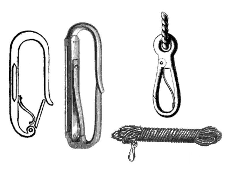
The fire brigade of Berlin, Prussia (now Germany) was among the earliest to use carabiners, being well established by 1847. Initially, they called them "Gurthaken" or "Gurthacken" ("belt hook"). They were used as an equivalent to a cows tail. No other uses were stated at the time, but they had to be able to support the weight of a human, and they are the first known carabiners to be capable of that. The design, known as the "Berliner Gurthaken", can be seen in an 1850 publication and an 1877 publication, and had to be large enough to fit over the rung of a ladder. Rather unusually, it did not have a captive eye at one end (unlike most subsequent designs), because it had a leaf spring inside the loop of the carabiner, which effectively divided the carabiner in two, and got in the way at one end of the carabiner. The gate, which did not have a a load bearing latch, was hinged next to the spine of the carabiner, and this prevented loads from being hung from that end of the carabiner. So the captive eye was a long slot in the spine of the carabiner, which had a strap from the belt passing through it, so that rather than being a proper cows tail, it forced the belt to be right next to the ladder that it was clipped to. In 1849, American Walter Hunt reinvented the safety pin, which may not be a carabiner, but its design is very similar to the first wiregate carabiners. And the United States Patent Office accepted it, even though it was virtually identical to several fibulae brooches created 3200 years before. In the same year, Charles Rowley independently reinvented the safety pin in Britain, and the British patent office also accepted it as a new invention. Patent offices don't seem to be particularly meticulous when it comes to detecting prior art. There is the suggestion that Charles Rowley invented it long before Walter Hunt, and took too long to register the patent, but the reality is that both of them were 3200 years too late for it to have been an original invention. An extremely well developed British swivel carabiner had a small captive eye at the narrow end, a sprung gate, and a load bearing dovetail latch. This, and the fact that it was connected to a chain, make it likely to be from some time after the 1790s, in spite of it being provisionally dated to the 1600s. The sling colours and insignia match the Royal Welch Fusiliers from 1850-1915.
In 1851, fire brigades in Ulm, German Confederation (now Germany) were using small carabiners 7.5 cm wide and 2.5 cm long, to clip ropes to their belts to leave their hands free while climbing. The design was extremely similar to the old carbine rifle carabiners, with a captive eye and a flat spring visible inside the carabiner's main loop. The carabiners were not load bearing, without a load bearing latch, and were only used for temporary storage. By 1855, fire brigade carabiners were referred to as "Karabinerhaken", and they were already referred to as "rescue carabiners", so they may well have served other purposes too, such as for lowering people. American carbine sling swivels from 1855-1865 (including the American Civil War) had captive eyes and spring loaded gates, but used a basic tongue instead of a load bearing latch, though versions imported from Britain had a dovetail latch. By 1859, the Austrian (at that point a part of the German Confederation) fire brigades were using carabiners. An 1859 design by American Morris Pollack used an S-shaped body with opposing gates at both ends that opened at the same time as each other; the first S-carabiner. Carabiners were used to support a person as part of several commercially available fire escape descenders, starting from 1860 in the USA, with many different designs being used, often based on the old swivel carabiners. From as early as 1861, Austrian fire brigade suppliers such as Wm. Knaust from Vienna (who later supplied the mining industry too) incorrectly called them a "Carabiner", meaning "carbine rifle" instead of the more correct "Haken", meaning hook. This is the first time the modern name is known to have been used, and it was spelled with a "C". Carabiners were used in American Civil War cavalry link straps (for linking horses together) in 1861. During that same war, the older design of swivel carabiners also started to be used for holding the drums of American military drummers, replacing the hooks and tied straps that were used during the American Revolutionary War.
Carabiners then rapidly expanded into numerous designs for a variety of purposes, and started to be called "spring hooks", "snap hooks" or "safety hooks". Many patents show smaller models, designed for lightweight tasks (such as connecting a strap to a handbag) or for connecting ropes and straps to animals, including horse tack again. Most of these are not relevant to caving, except the handbags, of course. A proliferation of spring designs then appeared, only a few of which are important here. An 1862 design by American Robert A. Goodyear had a hidden spring. An 1863 design by American Norman North had a gate spring pushing on a hidden lever, like a modern carabiner. An 1863 design by American Samuel Babcock had a flat spring hidden inside the gate. An 1864 design by Americans R. E. Gorton and A. Gorton had a hidden compression spring (like a modern carabiner) hidden inside the body of the carabiner, as well as a dovetail latch, the first time it was depicted in America. This idea was registered again in 1889. An 1864 design by American Oliver S. Judd used a torsion spring like a safety pin.
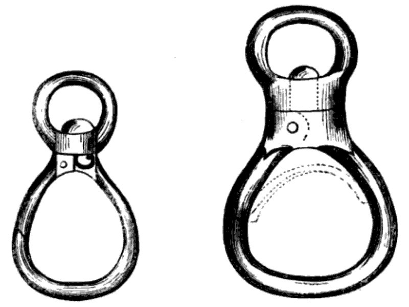
Around 1864, a new design of carabiner emerged in Leipzig, Kingdom of Saxony, German Confederation (now Germany), which became known as the "Leipziger Gurthaken", the Leipzig belt hook. It had a captive eye, covered torsion spring, did not have a load bearing latch, and was extremely large, so that it could fit over thick ladder poles rather than rungs. Though the size is not stated explicitly, a later description appears to refer to it, saying that it was 19 cm long and 12 cm wide, and made by Reichenbach. This was being purchased by fire brigades in Berlin around the end of 1864. In that same year, German and Austrian fire brigade suppliers attended a trade fair in Leipzig, and this seems to have spread the idea of hidden springs to other manufacturers. In 1865, fire brigades from Leipzig were using carabiners with a captive eye, a swivel joint, and a gate (referred to as a "barb") which did not have a load bearing latch. They were expected to hold 200 kg without bending, and will have been very large and heavy. There were two models, one with a traditional flat spring visible in the middle of the carabiner's body, and a more expensive one with a bent flat spring next to the gate's hinge, which pushed it closed. While the spring could probably be seen, it did not waste space inside the carabiner. This was the first design that German fire brigades referred to as an "internal spring", and avoided the damage and associated repairs that resulted from ropes and ladders rubbing against exposed springs. However, the spring was fairly weak, which could be problematic. The origin of the design is not known, or which design was actually developed first, but the design known as the "Leipziger Gurthaken" is the one that became used elsewhere. The terms "Karabiner", "Karabinerhaken", "Sicherheitshaken" ("safety hook") and "Gurthaken" were all used to refer to carabiners. In addition to previous uses, they were used to lower a firefighter out of a building on a rope by clipping the end of a rope to their belt, or to join ropes by clipping to a ring attached to one end of the rope. Firefighters also used them to clip a fire hose to their belt, leaving their hands free to climb a ladder.
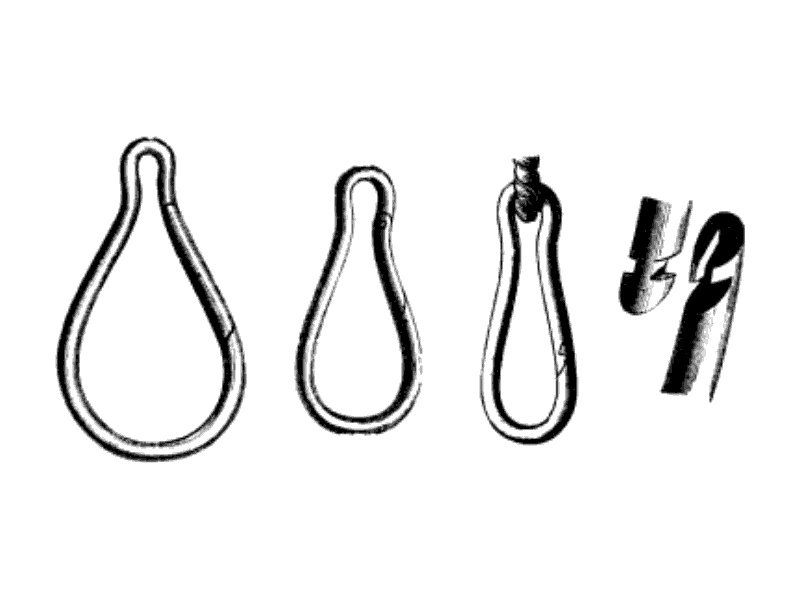
In 1868, fire brigade manufacturer Conrad Dietrich Magirus, who ran Magirus in Ulm, Kingdom of Württemberg (now Germany), developed the gourd-shaped carabiner, which became known as the "Ulmer Gurthacken" or "Ulmer Gurthaken" (the "Ulm belt hook"). While many earlier designs remain in common use, this is the first design of modern carabiner to remain in very common use today (though not within caving or climbing), which is immediately recognisable as a normal carabiner, rather than a spring hook, dog clip or luggage strap clip. One reason for the change is that the gourd-shaped carabiner could be removed from the belt when the belt wore out, and moved onto a new belt. They were the first type to hide a compression spring inside the gate like a modern carabiner (known in German as "Innenfeder", an "internal spring"), to prevent the spring being damaged by the rope. Initially, they did not have a load bearing latch, and they were available in three sizes, a small one to connect ropes to each other or to a belt for storage, a medium sized one to clip over the rungs of ladders with two poles, and a larger one to clip over the larger pole of single-pole ladders. The sizes were not explicitly stated, but they were likely to have been 9.5 cm, 15 cm and either 18 or 19 cm, judging from diagrams and the sizes sold later. The metal is likely to have been 13 mm thick on the smallest size, and 14 mm thick on the larger sizes. In spite of the gourd shape, they were often confusingly described as being round. Fire brigades in München, Kingdom of Bavaria (now Germany), were already recommending the gourd-shaped design by 1869. A swivel carabiner from the Netherlands in 1868 had a captive eye, with a chain connecting it to the swivel joint. The gate had an alignment tenon latch on the front of its tongue that was load bearing, but likely to be less effective than a dovetail. It is not known when this design appeared, since it is the only surviving example in the Dutch military museum collection. An oval link with an outwards opening gate was patented in 1868 by American William N. Pelton, with a load bearing pin that locked the gate, designed to connect snow chains to wheels. The gate was not spring loaded, so it would not normally be considered to be a carabiner. This almost exactly matches the design from 1485. An 1868 design by Americans William Cooper and William D. Rumsey used the same approach as a modern dog/trigger clip, and subsequent designs quickly became shaped more like dog/trigger clips.
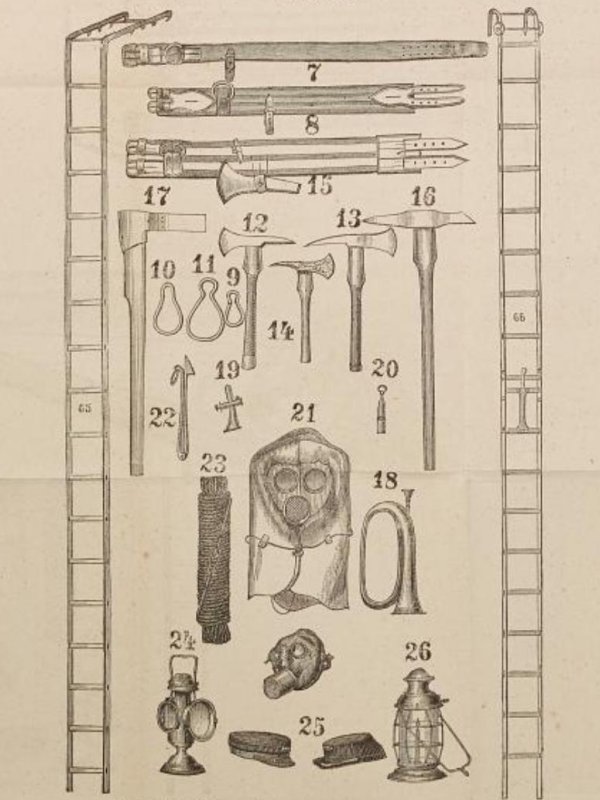
In 1872, gourd-shaped carabiners developed by Magirus were being sold in Vienna, Austria, Austro-Hungarian Empire, by Franz Kernreuter, intended for use by fire brigades. Hungarian fire brigades used the Leipzig design of carabiners in 1874, whose lengths were not stated, but the internal circumference (presumably of the main ring) was stated as either 37.5 cm or 55 cm, which correspond to about 20 cm and 26 cm in total length! In that year, fire brigades from Hungary, Austro-Hungarian Empire and München, Bavaria, German Empire (now Germany) used the term "Carabiner". In the same year, Austrian fire brigades were using the small carabiners on the end of a rope as a way to attach the rope to a wall hook, by looping the rope through the hook, and clipping the carabiner back around the rope, so that it only had to support half of the total load. In 1875, the Leipzig carabiner was already treated as an older design by German fire brigades. By that stage, they had already been using ropes with carabiners attached to both ends, to allow ropes to be quickly chained into longer lengths, or connected to an attachment. In 1877, Magirus (whose city of Ulm was now part of the German Empire, thanks to the chaos of German state history) stated that they had now adopted the dovetail latch into the gourd-shaped carabiners, which they called a "Zahnschloss" or "tooth lock". Initially, this was developed for smaller carabiners, but was then used on the larger carabiners within the same year. Their approach was exactly the same as the British design from about 85 years earlier (though much easier to do with the thick metal used for fire brigade carabiners), and could be made with as few as 7 cuts. This is how almost all dovetail latches are still made. Conrad Dietrich Magirus stated that they had also tested carabiners with a pinned latch. No details are given of how the pin worked, but it could be that he was referring to the tenon latch used in the Netherlands in 1868, or it could be that they had developed the nose hook and pinned latch which is used today, but either way, they could not make it strong enough in 1877. Magirus had tested iron and mild steel carabiners, both with and without the dovetail latch. Without it, iron carabiners already elongated by 1 mm at 100 kg, permanently stretched 1 mm after loading at 200 kg, and unrolled at 600 kg, while steel carabiners elongated by 1 mm at 200 kg, permanently stretched 0.5 mm after loading at 300 kg, and unrolled at 800 kg. With the dovetail latch, steel carabiners did not even start to elongate at 800 kg, showing the dramatic change in strength that the load bearing latch provided. These tests were done using carabiners that had a 9.5 cm external length, 7 cm internal length, and had metal 13 mm thick. A modern (non-PPE) gourd-shaped carabiner made from a similar mild steel, 13 mm thick, could hold 2.4 tonnes! In addition, the dovetail latch stopped the gate from slipping sideways out of position. In 1877, gourd-shaped carabiners were still being sold in Vienna, and used by fire brigades in Hungary, Austro-Hungarian Empire. They were stated as being able to hold 100 kg without bending, so they presumably did not have the load bearing latch yet. Walser from Pest (now Budapest), Hungary, also sold carabiners for the fire brigades in 1877, and these may have been the Leipzig design. An 1877 design by American Lewis E. Walker had two opposing clips with the same orientation, a variation of the S-carabiner.
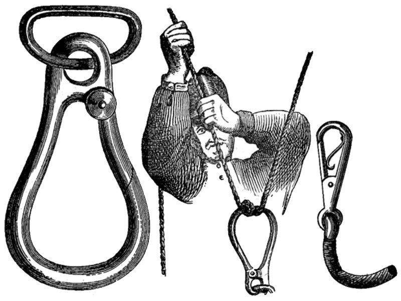
In 1878, Fire brigades from the Stuttgart region of Germany were using their large carabiners as a descender for abseiling, using a carabiner wrap. They are depicted as using the Leipzig carabiner design from 1864, even though it was already out of date by that stage, so either they were still using the old design, or the drawing is from several years earlier, perhaps before the gourd-shaped design took over in 1868. They would use carabiners to connect ropes to supports held up against a window frame. They would join ropes together using relatively small carabiners. They would have carabiners on belts and sit harnesses, which could be connected to the end of a rope, and used to lower people from a building. They used carabiners in the same way for lowering furniture. Carabiners were a major part of the fire brigade toolkit, and they were available in big and small designs, each strong enough to support a person. In 1879, German mountaineer Carl Seitz of the German and Austrian Alpine Association climbers/mountaineers, was using belts with carabiners, based on the fire brigade designs, to allow people to easily connect and disconnect from ropes when taking tour groups over icy mountains in the Alps. This is the earliest known use of carabiners by mountaineers/climbers, but it is quite likely that others had already been using them, without there being any known surviving documentation of it. In 1880, the Austrian fire brigades were shown using traditional teardrop/pear-shaped carabiners with a captive eye, but this is likely to be an older illustration. An 1880 design by American Joel Jenkins made the entire "snap hook" out of wire, so a wiregate and also a wire hook, following the approach of a safety pin. By 1881, the German and Austrian Alpine Association were recommending the use of carabiners for connecting to ropes, which they obtained from Joh. L. Petzl (no relation to the current company Petzl) in Vienna. They would use them in an emergency to retrieve someone who had fallen into a crevasse. The carabiners would have their club initials hammered into them, for identification. An 1881 design by Canadian Charles Barlow was intended to be used for lowering someone out of a building, as a fire escape. An 1882 design by the German Lohner brothers, made for the fire brigades, had a load bearing dovetail latch, and a pulley with a braking lever, which could be used as a descender or like a mechanical belay device! In 1882, climbers from the German and Austrian Alpine Association climbers/mountaineers were purchasing fire brigade ropes with carabiners. An 1883 design by American Oliver Benson used an S-shaped body with opposing gates at both ends that opened at the same time as each other; another S-carabiner. A design patented in 1883 by American Luke Chapman worked exactly like a modern screw gate, with a screw sleeve on a threaded gate. The patent also states that the sleeve could be put on the body of the carabiner instead of the gate, but that it is preferable to have it on the gate. By 1884, the German mining industry was using carabiners attached to a miner's belt to connect them to ropes for safety. The publication does not show them, but shows a few of the spring hook carabiners that were in use with German mining. An 1884 design by American James H. Farmer also had two opposing clips with the same orientation. Subsequent patents used the exact same approach, and did not deserve to be granted a patent. By 1885, German fire brigades in the München area were using carabiners that were 19 cm long, presumably gourd-shaped. That year, the German and Austrian Alpine Association were complaining that carabiners could open when pushed against the rock, if they had been used for a while. A pair of designs, one oval and one with a captive eye, both created in 1886 by American Edward H. Smith had a spring loaded pin lock, like EDELRID's Pure Slider lock.
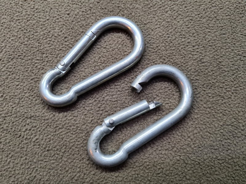
By 1887, carabiners were used by the German and Austrian Alpine Association climbers/mountaineers. Ropes with carabiners attached were stocked in Alpine huts in what was then Austria, now Italy. These will have been basic gourd-shaped carabiners with dovetail latches, made from mild steel, and not very strong. A typical strength was 100-120 kg. These continued to be used by climbers/mountaineers in Germany, Austria, and what is now the Czech Republic, until after 1920. The gourd-shaped design of carabiner became known as the "Feuerwehrkarabiner" ("fire brigade carabiner"), even if the specific carabiner was not in fact strong enough to be used by the fire brigades, and this confuses many sources into thinking that climbers were using actual fire brigade carabiners, which were much larger, heavier and stronger. It is likely that most carabiners that were used for climbing were originally made for the mining industry. The gourd-shaped design of carabiner is still commonly sold today for a variety of purposes, but almost never PPE rated. An 1888 design by American Edward A Wilson used a wire gate on a solid snap hook, possibly the first to do so. Previous designs had used the wire either just to make a spring, or as the gate, spring and hook at once. An 1889 design by American Winfred J. Smith had an inbuilt pulley for sliding along a rope or cable, exactly like many modern via ferrata cows tail carabiners. Much of the usage and development of carabiners within climbing took place in the Sächsische Schweiz mountains in eastern Germany and what was then the Austro-Hungarian Empire (now northern Czech Republic), and was not publicised as much as in other regions. Surviving photographs from 1892 show climbers using gourd-shaped carabiners. They could be clipped to a piton and used as a pulley for hauling, or to connect a climber to a piton for safety, or as a descender. It is not known exactly which country would have used them first for each of these purposes, but most of the climbing took place on the German side of the border, and the Austro-Hungarian side of the border was, at the time, mostly populated by Sudeten Germans (German Bohemians), so either way, their usage is likely to be German in origin. An 1893 design by American Charles H. Smith had an S-shaped body, with two trigger clips. An 1896 design by German Otto Fechner had a captive eye for a rope at one end, and a hook with a sprung metal gate at the other end. A locking sleeve could be turned to sit over the lip of the gate. This was the first twist gate, but since it was not self closing, it functioned more like a screw gate, which needed only half a turn to engage. French arborists were using carabiners in 1896 to support themselves in trees. Their design was a smaller version of the much older type of fire brigade carabiners, with a captive eye. An 1897 design by Canadian Reuben C. Eldridge had an S-shaped body, with two separate gates, just like a modern S-carabiner. A supposedly tough 1897 captive eye design by American Albert Moritz had an inwards opening sprung gate, which was not load bearing or lockable.
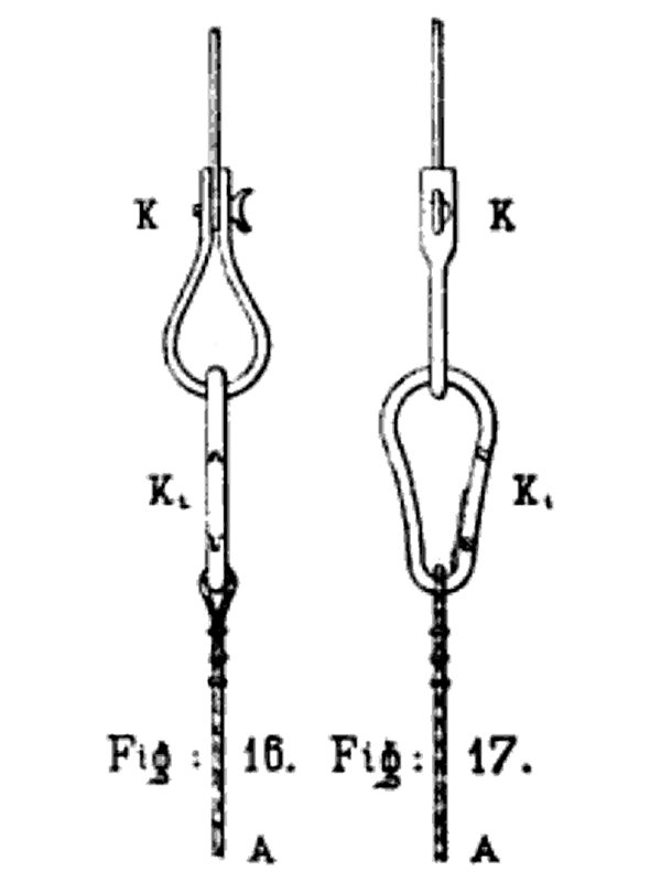
C. Wissemann reported that climbers/mountaineers were using carabiners as a descender and to connect to ropes in 1898 in Germany/Austria, but good ones were hard to obtain in 1899. By 1902, the Austrian mining industry was using carabiners for many tasks, and the gourd-shaped design had been relaxed so that the sides were now almost straight. This was the precursor to the narrow pear-shaped design, and was depicted as being in use in what is now the Moravskoslezský Region of the Czech Republic, but was then the Austro-Hungarian Empire. German mountaineer Hans Leberle described how in 1903, he and two climbers identified as Bachschmid and Schneider had used carabiners on the Zugspitze on the border between Germany and Austria. No details of their use or design was given, but the article described them being used on days when they were not using ice axes, so presumably it was not just walking over glaciers, and the rest of the article talked very clearly about climbing. A 1904 oval design by Americans Joseph Eugene Borlaug and Julia Borlaug had an outwards opening gate with a spring loaded safety catch that kept it closed (very similar to an EDELRID Pure Slider lock), designed for snow chains. It did not have a sprung gate, and would not normally be considered to be a carabiner. Another 1904 design by American John Emil Johnson used a screw threaded sleeve over the gate, but with the screw sleeve on the body of the carabiner instead. The screw sleeve was in a different position on the body from where Luke Chapman had described as an alternative in 1883, because the depiction was of a spring hook where the hinge was placed at the opposite end of the gate. However, the text also described a standard carabiner, where Luke Chapman's patent would have had prior art. By 1908, gourd-shaped carabiners and captive eye versions, both with dovetail latches, were being used by the mining industry in areas that are now Germany, and were the most likely source of climbing carabiners. While the design was slightly more gourd-shaped than the Austrian version, it was not as extreme as it had been in the previous decades, and the whole industry was moving towards smoother curved designs. They still also used older designs, with visible compression springs for the gate, and without load bearing latches. The smaller carabiners were stated as being stronger than the larger ones, with the larger ones (which were popular with the fire brigades) failing to survive drop testing at a fall factor of 0.75 with a mass of 75 kg on a Manila hemp rope, while the smaller carabiners survived it. By that time, many German references called the older gourd-shaped design a "pear-shaped" carabiner, but it is quite different from what is now called a pear-shaped carabiner in English, and this confuses some sources into thinking that the narrow pear-shaped design emerged earlier than it actually did. Several 1909 designs by Germans Pick & Fleischner used the springing power of the carabiner's spine to make a gate lever stay open or closed, creating the first captive carabiner with a divided loop (similar to a Mammut Smart or DMM Belay Master). A 1909 design by American Frank E. Schartow was an S-carabiner where both gates opened at the same time, where the load pulled on a lever to keep the carabiner closed. A 1910 design by Thomas D. Owen used a wiregate with the now normal U-shaped construction latching onto a small nose, intended for use with horse tack. The springing power came from the wire, like a modern wiregate, but used the spring itself as the hinge instead of having a hinged joint. By July 1910, German climber/mountaineer Hans Dülfer was using carabiners as a belay device, presumably using a carabiner wrap.
German climber/mountaineer Otto "Rambo" Herzog is mistakenly credited with developing the first climber/mountaineer's carabiner in 1910-1911, after seeing carabiners on belts of the local München fire brigade uniform. However, while he did use carabiners, the majority of claims made about his contributions are incorrect, and the facts behind the myth are much less dramatic. So much nonsense is repeated about him in relation to this subject that it is hard to find the actual information, but it is highly unlikely that he ever designed or made any carabiners himself, since he was trained as a carpenter, not a blacksmith, and he never wrote about making one, and never patented anything. It is most likely that he simply bought carabiners and used them, and just in case it needed to be said, that does not count as an invention. He probably started using them in 1912 (a year before he used them for a climbing tension traverse), in spite of his peers complaining about climbers using artificial aids. The low quality carabiners he used were made from mild steel, and would sometimes open accidentally because they were weak enough to flex too much, being only just able to hold the weight of a person. Even though many sources like to show them as a narrow pear-shaped carabiner, it is almost certain that he first used a gourd-shaped design. That is the only design mentioned in climbing newsletters from Germany and Austria, the areas where he was climbing, until the 1920s. Although he was trying to immitate a fire brigade design, it is more likely that he used carabiners that were sold for utility purposes, rather than the larger types sold for the fire brigades. They were also not even slightly the first carabiner, or the first used by climbers, or the first modern shaped carabiners, or the first carabiners capable of holding a person, or the first modern rated carabiners. In fact, carabiners designed for holding a person had existed for 65 years at that point, and climbers/mountaineers had been using them for over 30 years. (Even if he had made them himself, the only thing he would have "invented" was the idea that a carabiner could be created by a climber/mountaineer, and subsequently be used by a climber/mountaineer, something which is not really an invention at all.)
Paul Preuss, one of the most vocal critics of aid climbing and the use of any artificial climbing aids, died in a serious fall in 1913, because he did not have adequate protection. Artificial aids suddenly became acceptable, and climbers started using carabiners more heavily. Like many other climbers before him, Otto "Rambo" Herzog had already insisted on using carabiners and was putting them to good use, and because of the lucky timing, many people now think he invented them. He didn't. The myth seems to have originally developed as a result of a 1939 second hand mention of when he had first used carabiners, in which it was never claimed that he invented them or was the first climber to use them. It simply said that by some time in 1912, he was "already using carabiners on an experimental basis". Congratulations, many other climbers had been doing so for decades. The myth then became established as a result of a 1968 article in Alpinismus written by Austrian mountaineer Toni Hiebeler, and translated into English in 1969. The article rightly points out that evidence suggests that others such as Hans Dülfer had already used carabiners, even though Otto "Rambo" Herzog had used them before Hans Dülfer's 1912 ascent of the Austrian Fleischbank (perhaps the article's wording confused people into thinking this happened before 1910). However, it failed to notice the 30 previous years of carabiner usage by climbers/mountaineers, which had been documented by the German and Austrian Alpine Association. Otto "Rambo" Herzog's climbing partner German Gustav Haber gave the origin story about carabiners being seen on fire brigade belts, and did not suggest that Otto "Rambo" Herzog had made any himself. Gustav Haber specifically stated that the fire brigade's gourd-shaped design was used (which he referred to as pear-shaped, like many Germans did at the time), and that as far as he knew, a fire brigade device had been used. The mistaken idea that Otto "Rambo" Herzog was the first to use them was created by people that he spoke to, who had not seen anyone else use them, and incorrectly assumed he was the first to do so. His own nephew was one of the people making the mistaken claim, which reinforced the myth. The myth then appeared in books in 1990.
It should be noted that what would later become Nazi sentiment was already very strong in southern Germany and Austria by the late 1800s. This was particularly noticeable within the various Alpine clubs, who after having adopted rules to exclude others very early on, went to great lengths in the early 1900s to erase records and rewrite history, making themselves appear to have been first for a lot of things that they were in fact not the first to do. This became an intentional government policy during the 1930s and 1940s, and it makes historical research quite difficult, as the books that proved otherwise may literally have been burned, and the historical record intentionally polluted. Another example of this is the development of the Prusik knot and its applications. Therefore, it is quite likely that the attempts to promote a southern German false hero as the first to use carabiners for climbing were done very intentionally, as they may not have been aware of the actual origin, or which ethnic group their climbing use originated in.
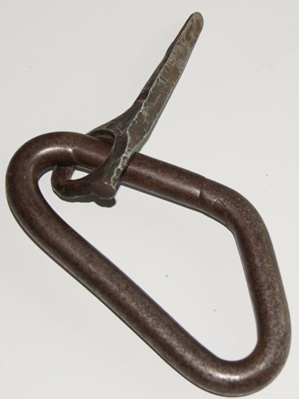
Climbers still like to claim that he invented carabiners over 400 years after they were actually invented, just because he was a climber, even though climbers were already using carabiners a decade before he was even born. By that measure, cavers should claim that a caver invented them because at least one caver actually made one many decades after cavers started using them, sailors should claim that a sailor invented them, the mining industry should claim that a mining engineer invented them, fire brigades should claim that a firefighter invented them, kite surfers and keyring makers should claim that ... well, you can see where this is going. Things get invented when they get invented, not when someone with a particular hobby makes one of them or uses one of them. The Messner Mountain Museum has an asymmetric offset triangular carabiner with curved corners, which they say was used by Otto "Rambo" Herzog and Austrian mountaineer Hans Fiechtl in 1920, a design which was used (but not popular) until the 1960s. Reinhold Messner, owner of the museum, stated (personal communication) that Otto "Rambo" Herzog had obtained their carabiner locally and used it for climbing, and had not designed it or made it himself. The suggestion was that this carabiner had been borrowed from a fire brigade workshop. However, it is not known if this design of carabiner was ever actually used by the fire brigades, and there is no evidence to show if the actual source of the carabiner had anything to do with the fire brigades, or whether this is simply another version of the myth. There is also no known evidence that Otto "Rambo" Herzog ever used it, or that it existed in 1920, since this design was only recorded in the 1930s. (Hans Fiechtl did actually design metal pitons and have them made by a local blacksmith, but their manufacturing quality was far too low for him to have been the source of the earlier carabiners.)
In 1920, the use of carabiners for climbing was described in detail in a German and Austrian climbing newsletter article called "Das Versichern beim Klettern" by mountaineer Hermann Amanshauser, based in Salzburg, Austria, very close to München in Germany. (He ran a mountaineering shop aimed at skiing in 1926, and taught skiing and climbing to young mountaineers, but seems to have become better known as a Nazi SS officer and skiing instructor before and during World War II.) As well being as the earliest widely distributed climbing publication to describe the complete approach of using carabiners attached to pitons, and running ropes through them for safety while belaying as they are still used today, it also described them as being used as a belay device, using a carabiner wrap. Gourd-shaped carabiners were shown as being 10.5 cm long, using metal that was 10 mm thick, referred to as a "so-called fire brigade carabiner". The article stated that the gourd-shaped carabiners were very suitable, but "oval" carabiners were better, though it did not say whether this referred to a modern oval, a narrow pear shape, or an elliptical carabiner.
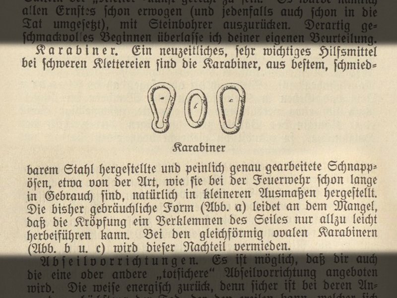
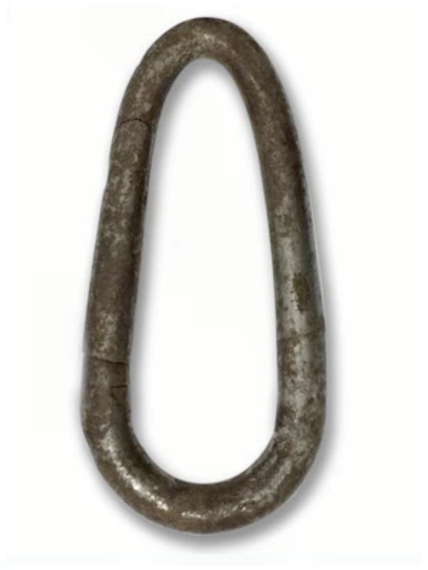
Elliptical carabiners (curved all the way around) with a load bearing dovetail latch were shown in German mountaineer Franz Nieberl's book Das Klettern im Fels in 1921, published in München. However, they were very weak due to the way the curve could load the gate. In earlier decades, the gourd-shaped design had been the most popular, but by 1921, Franz Nieberl referred to it as the "previously used shape". The same book showed narrow pear-shaped carabiners with a dovetail latch, and this is the first time they are conclusively shown in relation to climbing, stated as being less likely to trap the rope than the gourd-shaped design. Presumably they had started to be used for climbing either in 1921, or they might be the "oval" design referred to in 1920. These narrow pear-shaped carabiners are almost exactly the same as the mining design used in the Austro-Hungarian Empire in 1902, with the only difference being that the sides were straight or slightly bent outwards instead of inwards. This difference might not have been intentional, and could just as easily have been because a different company was making them, or a different manufacturing machine was being used to bend them into shape, because of the stronger steel and load bearing latch which the 1902 version did not have. Surviving examples have sides that bend inwards or outwards, due to inconsistencies in their manufacture. The publications did not give the source, but many sources stated that climbers were buying their other metal hardware in hardware shops, not specifically made for climbing (with the exception of pitons). Das Klettern im Fels explicitly stated that the carabiners were smaller than the versions used by the fire brigades, so the fire brigades were not the source, but that they were finely crafted from the best forged steel, with extremely well made gates. They are therefore likely to have come from a major industry with excellent production methods, likely to have been the mining industry. German references subsequently called the narrow pear-shaped design an "oval" or "round" carabiner, since it is actually oval (like an egg), unlike what would currently be called oval. It is no longer used for carabiners, but this shape is still used for some maillons.
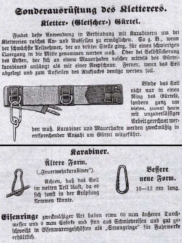
Many modern sources state that the narrow pear-shaped carabiners weighed 130 grams, but they are simply copying each other without checking actual carabiners. This number seems to have originated in Toni Hiebeler's article, which blindly stated that all previous carabiners used for climbing before 1939 had weighed 130 grams, which is clearly nonsense, since they were available in multiple sizes, using different thicknesses and different designs. In 1922, Anwendung des Seiles showed three designs of carabiners. The gourd-shaped design was referred to as a "Feuerwehrkarabiner" meaning "fire brigade carabiner", while the other two designs had no name, and all three were called "Karabiner". The second design was the narrow pear-shaped design, which was stated to be better than the gourd-shaped design, because the gourd-shaped design could accidentally trap the rope at the narrower end. It was described as a new design, between 10 and 12 cm long, and since this booklet was published in the same city as Das Klettern im Fels, it suggests that the design had not been used for climbing in that area until about 1920. Alongside those was an oval carabiner with identical half-circle ends and straight sides, just like a modern oval carabiner. It was very clearly drawn, with a load bearing dovetail latch. Its purpose was stated as being used for glacier crossings, using the method described by Carl Seitz, or clipping to a piton for safety. Both the narrow pear-shaped design and modern oval design were shown being used for catching climbing falls.
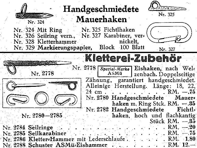
German climber August Schuster ran an alpine sports company in München called Sporthaus Schuster, which still exists. In the summer of 1924, Sporthaus Schuster was selling modern oval shaped carabiners, which they simply called a "Karabiner". (Toni Hiebeler's article mistakenly said this was in 1921 and cost DM 7.50, but it was actually in 1924 and cost just DM 0.70.) This was stated as being made with nickel, so it was presumably nickel plated steel, and had a load bearing dovetail latch. It was featured in the same section as pitons, so it was intended to be used for climbing. This is the first known commercial sale of any carabiner for this purpose, but it is highly unlikely that they were being specifically made for climbing, and were probably just rebranded as climbing carabiners. They were probably sourced from mining manufacturers or general hardware manufacturers, but they did not have any branding to show the origin. The Sporthaus Schuster catalogues show that they started to use the "Shuster" branding on their own custom made products from the winter of 1924-1925 and the ASMü branding in the early part of 1925, but their carabiners remained unbranded, which suggests they were never specifically made either for climbing or for Sporthaus Schuster. Also in 1924, the modern oval design was depicted being used for climbing in the same region by Ernst Platz. In 1925, Sporthaus Schuster started calling carabiners "Seilkarabiner", meaning "rope carabiner", and started selling the narrow pear-shaped carabiner in addition to the modern oval carabiner. In 1926, Anwendung des Seiles again showed the same designs of carabiners, but none were shown in relation to crossing glaciers. Stronger steels started being used in the 1920s, and carabiners were then considered more reliable, though they could still only be trusted to catch shorter falls. The earliest known D-ring carabiner was made at some point during the 1920s, but its origin is unknown. The gourd-shaped designs remained in use by climbers until the late 1920s.
When carabiners started to be used for climbing in English speaking countries, climbers forgot that they had already existed in those countries for centuries, with no less than 4 English names already. Instead, they acted like they were a new invention, and called them by the incorrectly shortened version of their German name, a mistake which has endured for the last hundred years, and even made its way back into German in industries that had previously used the correct name. Carabiners were mentioned in English literature from the late 1920s, with "carabiner" being 2-4 times as common as "karabiner" until the early 1950s. A 1927 design by American Ernest J Shaffer was an S-carabiner with single wire gates, similar to some modern carabiners like the Petzl Ange. By 1928, the narrow pear-shaped design was being sold in Sporthaus Jungborn in Dresden, near the Sächsische Schweiz mountains. By 1929, both the modern oval and narrow pear-shaped designs were being sold by Mizzi Langer in Vienna, and they were called "round oval" and "pointed oval" respectively, names which would be adopted by Sporthaus Schuster by 1934. In 1930, modern oval carabiners were depicted again in Anwendung des Seiles. They were referred to as "round", with the narrow pear-shaped carabiners now being called pear-shaped in German. The narrow pear-shaped design was still preferred because it made it easier to see the gate. Both were available in smaller and larger sizes, with the smaller size being normally preferred. During the 1930s, they became very popular for climbing, and the strength soon reached around 1 tonne. The modern oval design became the main one used for climbing during the 1930s, and carabiners of this design are still used for caving today. They are also a very common design used in rope access, and many rope access devices are designed to be used only with oval carabiners.
French mountaineer Pierre Allain made the first aluminium alloy carabiners from duraluminium before 1939, but these were never sold. The exact date is not known, but the most reliable sources say 1932-1933, while others say 1937, 1938 or 1939. The first prototypes were asymmetrical/offset oval carabiners, whose ends were slightly more curved at the backbone side than the gate side (the first step towards D-shaped carabiners), which allowed them to be lighter for the same strength. The prototypes are likely to have been the first carabiner to use that design, and were the first carabiner known to be designed and made specifically for climbing, though they were not sold for that purpose until much later. In 1935, Sporthaus Schuster released screw gate steel carabiners, and this is the first time that climbers/mountaineers are likely to have used them. The offset triangular design is known to have been in use with climbing in the Sächsische Schweiz mountains during the later part of the 1930s. Although some carabiners had occasionally received identification marks as early as 1881, and surviving examples can be seen from 1931, it was not until very late in the 1930s that Italian company Grivel started producing theirs with branding, and these would have been the earliest known carabiners to be commercially produced explicitly for climbing. Others may have been producing them specifically for climbing earlier, but there is no known evidence for it. However, it should be noted that the branding is quite poor, and clearly not designed for a rounded carabiner, being the top half of the logo used for crampons in the 1930s. It is quite possible that Grivel were purchasing generic carabiners that had been made without climbing in mind, using a punch to strike a maker's mark into them, then selling them for climbing. The narrow pear-shaped designs fell out of use by climbers in the late 1930s. American William James "Bill" House and ALCOA first sold aluminium carabiners in 1941 for the Army, replacing the steel ovals they had been using. By 1943, these successfully used a nose hook and pinned latch, which may have previously been tested around 1877, or may have been a new design. They are likely to have been the first aluminium carabiners sold for climbing, and also the first commercial carabiners specifically designed for climbing, though they were only intended for use by American military climbers. Their strength was tested as 7-9.5 kN, which was comparable to the steel carabiners that the American military had been using at the time. The latch method was quickly adopted by most manufacturers, and became the standard latch used for climbing and caving carabiners until the emergence of keylocks. The nose hook and pinned latch still remains very popular for strong carabiners, particularly for use with rope access.
In 1942, Anwendung des Seiles showed narrow pear-shaped, modern oval and D-ring carabiners, which were now referred to as a "Schnappring", meaning "snap ring". They were available in larger and smaller sizes, with the larger size being the only one stated, at 12 cm. The D-rings were slightly asymmetrical, which matches the design seen in the 1920s example, and had a screw gate. The design was not named. Screw gate and snap-link steel carabiners were in use by French cavers by 1944. A variety of different designs were depicted by French caver Henry P. Guérin in that year, including pear-shaped (with a screw gate), elliptical, modern oval, gourd-shaped, and a pear-shaped design with a captive eye and swivel joint, which might be used for a cows tail. Italians Riccardo Cassin and Felice Bonaiti are credited with inventing the D-shaped carabiner, which would need to have happened in the 1940s, though the exact date is not recorded. These were sold by Kong in the 1950s. Pierre Allain first sold his aluminium carabiners around 1947, which were now D-shaped with a slight offset, but still without a load bearing latch. It is possible that Pierre Allain developed this D-shaped design before Riccardo Cassin and Felice Bonaiti had developed theirs, but either way, Pierre Allain's were sold first. American Raffi Bedayn is often credited with the first commercial sales of aluminium alloy carabiners in America in 1947. As a result, carabiners made specifically for climbing were being sold on two continents. Also in 1947, American one-man company Gerry, run by Gerald Cunningham, was selling home made carabiners, which were thought to be a new design, but which were actually the same as the offset triangular design previously sold in Europe. Over time, these became an offset D-shaped design, but by that stage, others had already been selling that design. In around 1950, Italian Ricardo Cassin was making D-ring carabiners. By the early 1950s, companies (including Kong) were producing properly offset D-shaped carabiners, which remains the most popular design in use today. Austrian mountaineer Sebastian "Wastl" Mariner created the relatively strong (12 kN) kidney-shaped MARWA carabiner in 1951, replaced later by a 16 KN model, but this soon disappeared as even stronger designs appeared. During the early 1950s, the spelling "karabiner" increased in popularity in English, and became slightly more common than "carabiner" until the 1970s. American Yvon Chouinard started selling stronger aluminium carabiners in 1957, which could hold the weight of a climber without loading the gate enough to prevent opening it. His company Chouinard Equipment (later Black Diamond) made the first modern rated 22 kN aluminium carabiner in 1968. This is presumably the first time that aluminium climbing carabiners could actually be trusted to take a shock load. However, even during the 1960s, some companies still made climbing carabiners without a load bearing latch, dramatically reducing their strength.
Screw gate locking aluminium carabiners were reintroduced in the 1960s by German company Salewa (about 80 years after they were initially patented). An auto-locking design was patented by Germans Paul Buettner and Wolfgang Buettner in 1962, using something similar to a door catch, but this design was not widely used. In 1963, British cavers from the Wessex Cave Club complained about how good carabiners were hard to find, and how imports of the strongest design had been refused an import permit. Carabiners were stated as being the weakest part of the system, which is quite the opposite of how things are now. The International Climbing and Mountaineering Federation (Union Internationale des Associations d'Alpinisme, UIAA) started giving PPE ratings for carabiners in 1965. A very low-strength 1968 design by American William E. Forrest used a hollow carabiner in a shape very similar to a modern pear-shape. Wiregates were used again in 1968 with clevis hooks (a hook connected at the end of a chain) by the American Peerless Chain Company, to turn them into spring hooks. The spring effect of the wire was used as the hinge, like Thomas D. Owen had done in 1910, but the gate could also be rotated out of the way when needed. The wire was U-shaped, with a significant indent that prevented it from rotating off the hook during use. Wiregates that used the now-common offset hinge to provide the springing power, first appeared in the maritime industry with snap hooks (very similar in shape to the original carbine clips), with French company Wichard patenting the idea in 1969 in France and Britain. The patent described several designs for the gate, including the normal U-shaped construction, and showed a ring design. Their historical timeline shows that they were selling a U-shaped design without a load bearing latch in 1970.
During the early 1970s, the spelling "carabiner" rapidly became far more popular than "karabiner" again in English, at times being 4-10 times as popular. By 1972, the offset triangle carabiner shape was being progressively modified towards the modern pear-shape in France. The modern pear-shape with a flattened top, unlike the previous narrow pear-shape which had a rounded top, was depicted as being sold in 1973, referred to as being pear-shaped. The manufacturer is not stated, but although they were shown in an American book, the design is absolutely identical in shape to the one known to have been sold at some point around that year by Austrian company Stubai, so they are the most likely source of that design. Their catalogue listings refer to it as a wide offset D-shaped design, showing that it was adapted from that, not from the offset triangle or narrow pear-shape. British company Clog were selling theirs by 1975, but are unlikely to be the original source of them as most of their designs were copies of someone else's, and their version has a distinctively different nose shape from what was shown in 1973. Chouinard Equipment made very similar versions much later, but even in 1983, their catalogue still showed only the earlier narrow pear-shaped version, so they were not making modern pear shaped carabiners in 1973. Salewa prototyped some of the first auto-locking gates in the 1970s and hollow carabiners in 1975, and by 1977, Chouinard Equipment actually sold the hollow Featherweight carabiner. Bent gates were developed by Chouinard Equipment in about 1975, and were sold commercially in 1980 under the brand name BentGate. Auto-locking twist locks were developed by Clog in the late 1970s, and announced as new in 1980, though they were only widely marketed in 1983.
Due to the UIAA complaining about the Italian Hitch locking up with standard D-shaped carabiners in 1980, pear-shaped HMS carabiners returned to popularity during the 1980s. The exact date of the first dedicated HMS carabiner is not known, but Chouinard Equipment were selling their dedicated HMS Pearabiner in 1983, which was simply a large version of the old narrow pear-shaped design. Wichard's wiregate patent was due to expire in 1983, and they apparently made a failed attempt to re-register a very similar design in France in 1981 (presumably to gain some more patent time). They registered a series of wiregate carabiner designs in 1981 in the USA, referencing the 1981 French patent application, and many other patents mistakenly treat these as the source of the wiregate design. The patents show that they were now using a load bearing latch with a hook nose. Wichard made wiregate carabiners that actually looked like modern wiregate carabiners in 1983. Similar carabiners were sold for the maritime industry by Italian company Kong during the 1980s. At the time, Kong made climbing equipment for themselves, Salewa and Chouinard Equipment, but when Salewa asked Kong to make wiregate carabiners for climbing some time before 1989, Kong refused. Keylock carabiners were created by French mountaineer Jean-Paul Fréchin at some point between 1984 and 1987, and the patent was sold to Kong, who refused to allow others to use it. It was not until Petzl subverted the patent, forcing Kong to license it, and started to use keylocks with their Spirit carabiners in 1993, that the approach became well known, and rapidly took over from the nose hook and pinned latches. By 1989, Chouinard Equipment had abandoned the narrow pear shape, and switched to the modern pear shape for their Pearabiner, wider than the Stubai design, with a differently angled top, better suited to the Italian hitch. This carabiner also featured a screw gate with the screw closing over the hinge end instead of the nose end in order to lock it, keeping the screw gate away from the rope, but despite being used on some other models as well, this approach soon lost favour because it was different from every other carabiner, and could easily lead to dangerous mistakes.
Prototype wiregates appeared in 1991 from Black Diamond (formerly Chouinard Equipment), based directly on the ones that had already been used for some time with sailing in Seattle, USA, rather than the ones sold by Kong. Black Diamond prototyped again in 1994 and released the first wiregate carabiner for climbing, HotWire, in 1996, over 25 years after Wichard started selling them for sailing. This brought nose hooks back into common use, and the snag frustrations were set to continue. S-carabiners re-emerged in 1996, 2007 and 2008 in the USA and China, with attempts to claim them as a new invention. British company DMM patented an anti-snag wiregate carabiner in 2000, which simply had the keylock applied backwards, so that the gate fits into the nose of the carabiner instead of the other way around. Several other carabiner designs appeared from 2000 onwards, aimed at less demanding tasks, mostly as novelties (which really confuse the whole patent system with design copyright), typically made from plastic. British company Wild Country released the first anti-snag wiregate carabiner (Helium) in 2004. Twin gate carabiners were patented by American Rocke P. Thompson in 2007. Petzl patented their idea of an anti-snag wiregate carabiner in 2008 which became the Ange, but it is really just a very thin solid gate with DMM's reversed keylock. The spring is hidden in the body of the carabiner instead of the gate, just like the 1864 design by R. E. Gorton and A. Gorton. The use of carbon fibre was patented in 2008 by Brian James Kelleghan, but has yet to appear in reality for such demanding purposes (it has appeared for a few novelty products only), despite British company DMM claiming to have looked into the possibility earlier. Black Diamond patented their version of an anti-snag wiregate in 2009, which adds wings to the nose hook, which try to deflect items and stop them from snagging. In 2010, Austrian inventor Franz Wurzer patented a carabiner with a double-ended gate, that could be opened at either end, depending on which end of the gate an auto-locking captive eye divider was pushed away from. Austrian company AustriAlpin started selling their Fifty:Fifty carabiner in 2013, based on this design. Grivel re-patented twin gate carabiners in 2014, with the only significant difference being that the gates hinged at opposite ends. American Tony Christianson patented a locking wiregate carabiner in 2022.
If you are still hungry for more information, John Middendorf's website contains details of the earliest climbing carabiners, as well as an earlier article about the same subject.
This history section only covers carabiners. This article also has a detailed history of many of the other devices and techniques that are used for vertical caving.
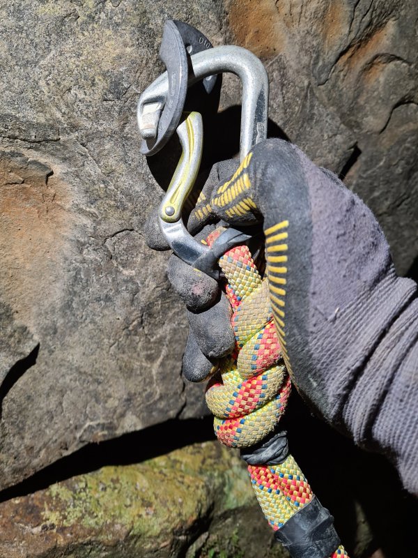
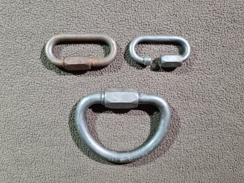
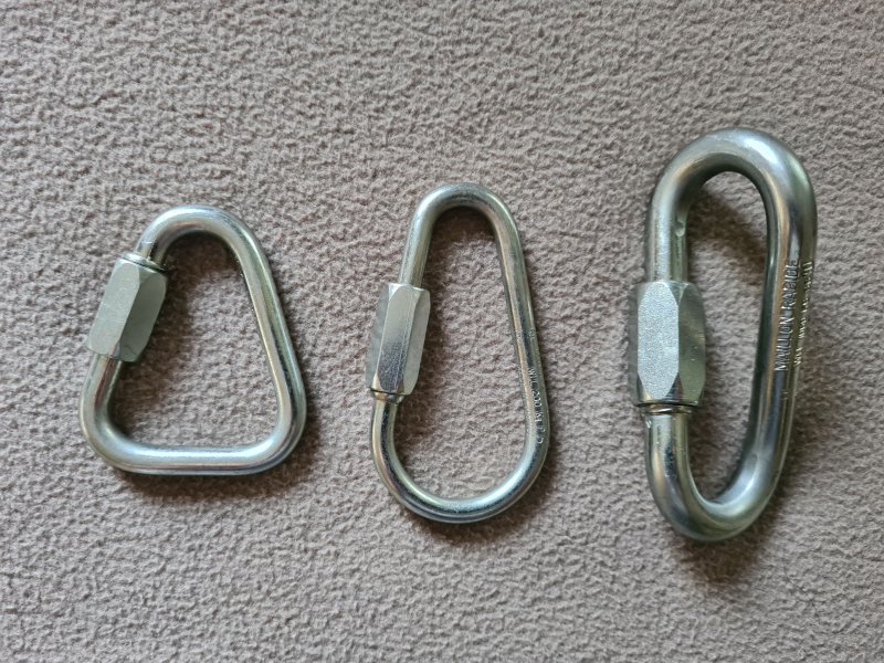
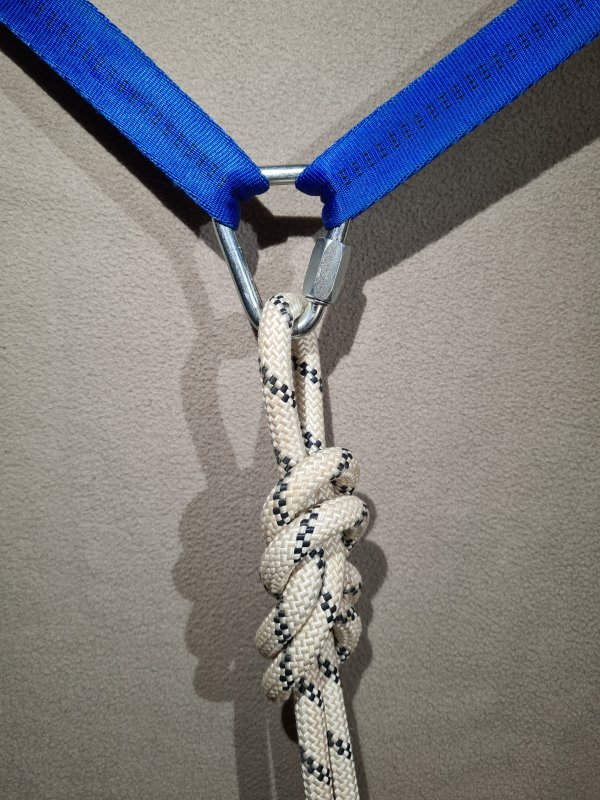
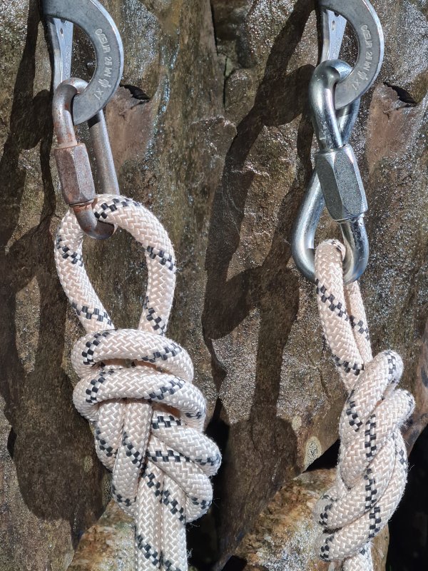
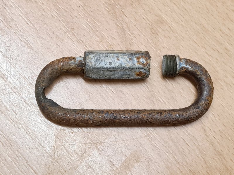
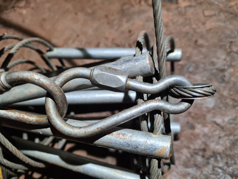
Similar to a carabiner, but the gate is not hinged. Instead, it is screw threaded so you screw it slowly across the gap. Much stronger. Much smaller. Much lighter weight. Much slower and more annoying to use. Generally used for rigging. Often used for a D-ring. Some are delta/triangular, to allow three directional attachments, or to allow flat straps like slings to lie along one of the edges. Some twist 90° along the length of the maillon, in order to rotate the equipment they are attached to, which can also be used to push a rope further from the rock, to avoid rope rubs created by some types of hangers. The ratings of maillons vary widely depending on whether they are made of aluminium or steel, and how big they are. If they are going to be used for life critical purposes, such as for rigging, they should be PPE rated (European standard EN 12275), with a minimum breaking strength (MBS) at or above 2.5 tonnes (actually given as a breaking strain of 25 kN), but especially strong versions may be rated as high as 22.5 tonnes, just in case you ever needed to play tug-of-war with a Chinook helicopter.
When used in reality on a hanger, a maillon with a stated MBS of 2750 kg, that would otherwise have broken at 3574 kg in a very careful test with a wide radius, would break at 2632 kg when pulled against a hanger; the hanger takes a tonne off the strength, compared with a wider radius. However, maillons can become damaged from heavy use, and at that point, the strength can no longer be assumed. Once damaged by rubbing against other equipment like hangers, so that a significant portion of the maillon's material is missing at one end, the strength loss is very complex. The notch concentrates the force, and sharper edges of the notch will increase this further. The specific type of metal will play a part. The strength of the maillon comes largely from its shape, with less strength coming from the material thickness, and so in actual testing, the strength loss was surprisingly little. However, there will be a point at which the strength loss dramatically increases, and catastrophic failure can happen quite suddenly. Corrosion has a similarly complex effect, depending on which part it has compromised, particularly if the screw threads are affected, and how far through the material the corrosion has advanced. As a result, damaged maillons should be replaced before the damage becomes significant, not assuming that it is possible to estimate how much strength remains.
French blacksmith Firmin Desbiolles invented and made the first maillons in 1923, for the purpose of linking chains for farming. He applied for the patent in 1941. Around 1945, he assigned the patent to Francis Péguet, whose family business Péguet has made them ever since.
This history section only covers maillons. This article also has a detailed history of many of the other devices and techniques that are used for vertical caving.

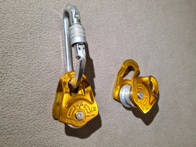
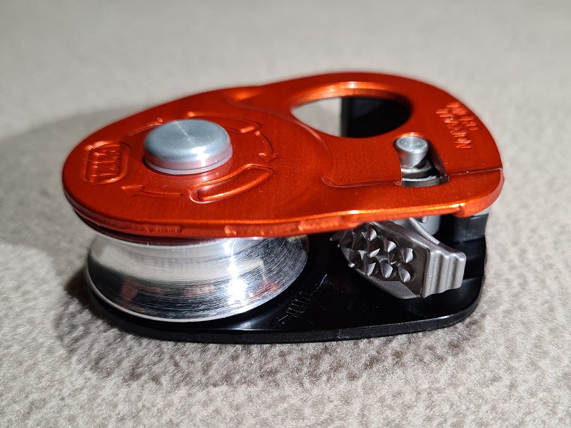
A wheel ("sheave") that the rope can run over, providing much less friction than if it just runs through a carabiner. In site of their benefits in many situations, it is more common to simply run the rope through a carabiner, and pulleys are generally reserved for a few specific uses. There are several variations, including dedicated pulleys with a housing that can be clipped to a carabiner, down to a basic wheel that is put onto an oval carabiner, using the carabiner as its axle. Most designs have to be removed from the carabiner they are attached to, in order to connect or disconnect them from a rope, and a keeper cord may be needed to avoid dropping them. Some have fixed sides, where the rope needs to fit through the gap between them, so they need to be used with a wide carabiner which pulls equally on both sides, so they work best with an oval carabiner. With fixed sided pulleys, other carabiners designs, such as D-shaped, can cause unequal or diagonal loading that may damage or break the pulley at surprisingly low loads. Many pulleys use swing cheeks, where the two sides can be rotated separately, allowing them to be separated to get the rope between them, and these tend to have no gap when closed, so they can work with almost any design of carabiner. Lightweight, small designs are often preferred, but the strength requirements may sometimes mandate larger pulleys. Some designs have a cam like an ascender which allows the rope to move only in one direction, specifically for use with hauling, and are known as progress capture pulleys. Many of these can also be used as an ascender.
A pulley may be used to allow an object to move along a relatively straight rope with reduced friction, such as for crossing a Tyrolean traverse, or as part of a chest roller. In these cases, the rope remains still, and the load is attached to the pulley with a pull direction roughly perpendicular to the rope.
A pulley can also be used for redirecting a force, such as for hauling equipment, top roping, the double bungee variation of rope walking, part of a Z-rig tensioning system, and as part of a rope washer. In these cases, the pulley is attached to a fixed object, one or both ends of the rope are pulled, and the rope changes direction at the pulley.
A pulley can be used as a force multiplier, doubling a pulling force at the expense of halving the distance moved (or vice versa, but they are rarely used that way). They are used this way with the Italian technique, Z-rig tensioning systems, and various types of improvised rescue. In these cases, the pulley is attached to a moving load, the rope changes directions at the pulley, and one end of the rope is pulled, while the other is fixed. Various configurations, such as redirecting the fixed end back to the load, can then be used to give 3 or more times the force, or pulleys can be stacked to double an already doubled force.
Pulleys can also be used to share a load equally between two anchors. For this, the two ends of the rope are fixed to anchors, the rope is given an amount of slack, and the load is connected to the moving pulley. The pulley will move along the rope until the force applied to each anchor is the same. This has traditionally been used to hang a ladder on the middle of a rope stretched over a pitch, to create the effect of a Y-hang. However, it lacks redundancy, and a failure of either anchor causes the ladder to fall, so this approach is not recommended.
Efficiency of pulleys plays a major role in how useful they are, especially when they are being used in Z-rigs and other force multiplier situations (see that section for some practical measurements). A pulley with perfect efficiency (something that cannot actually exist) would be able to redirect a force completely. If using a pulley with a terrible efficiency of 50%, pulling on one end of the rope with 10 kg would cause only 5 kg to be seen by the rope on the other side of the pulley. 35-45% is the approximate efficiency of a carabiner, so a pulley with an efficiency of 45% is basically pointless, as it could be replaced with a simple carabiner. An efficiency of 70% is fairly standard for pulleys without ball bearings (they use a low friction "bushing" instead), while extremely good pulleys with ball bearings and a large sheave tend to have an efficiency of about 90% (manufacturers may claim higher, but actual testing generally gives 85-90% for the best pulleys). These efficiencies are reduced when mud is involved, and generally get worse over time, with bushings normally wearing out faster than sealed ball bearings. Efficiencies are normally measured as the proportion of force that can be redirected by a 180° deflection (so the rope changes direction by 180° at the pulley), and the pulley's sheave must always perform a full 360° rotation during testing, just in case it has some rough spots. The efficiency is normally 1-5% higher for a 90° deflection (it does not follow a simple mathematical formula, since it relates to the friction of the rope, pulley surface and pulley bearings). With no deflection (meaning that the pulley is not involved at all), the efficiency is 100%.
Pulleys were used in 1991-1802 BCE in Egypt, though these were fairly crude, with ropes running over a grooved stone cylinder, and could not be connected to objects as needed. They were used for construction, so that people standing on a flat surface could haul something up a sloped surface. Pulleys were used to raise containers of water by the Sumerians in Mesopotamia in 1500 BCE. They were depicted in Assyria in 900-800 BCE, as a wheel used to redirect a rope that lifted a bucket of water. It is not known exactly when these developed into self-contained units. Archytas devised the mathematics that showed how to multiply forces using pulleys in 400 BCE, in what was then Greece, now Italy. Archimedes demonstrated their use as a force multiplier in Greece between 265 to 214 BCE, using compound pulleys to allow a single person to move a ship, and to allow cranes to lift a ship. He is credited with making the first block and tackle. During the middle ages, their use expanded along with the rise in sailing. In 1321-1337, a pulley is thought to have been first used to access a cave now called Covolo di Butistone in Verona, now Italy. It was being used as a fortress, rather than for active cave exploration, but this is the earliest known use of a pulley for accessing a cave. The pulley was described in 1664, but will have been needed from whenever the winch was installed, or perhaps even earlier.
Pulleys also formed an integral part of many winches, and so they will have been used in many caves, such as in 1595 by guano miners at the Gouffre de Padirac. However, this section will concentrate on pulleys that are separate from a winch's own structure. It is unknown when cavers and miners first started using pulleys in caves, but the first written record is from 1682, when British captain Greenville Collins explored Pen Park Hole using ropes and sailor's pulleys. Wooden ball bearings are known to have been used in a rotating table from a Roman ship in 40 BCE. They were used as a standard ball bearing and roller bearing by Leonardo da Vinci as part of the helicopter depicted in the Madrid Codex in 1493-1497, in the Holy Roman Empire, now Italy. They were used with a cage to guide the rollers by British inventor John Harrison in 1740, and then with a guiding groove by British ironmaster Philip Vaughan in 1794. The earliest known mention of roller bearings in a pulley is an American patent from 1810 by Mark Laighton, but it was destroyed in a patent office fire (along with all other American patents from 1790-1836), so the exact details are unknown, and it is not known if it was ever produced.
A British team consisting of John Birkbeck, William Metcalfe, William Howson and 7 others used pulleys to help lower cavers from the British Long Churn into Alum Pot in 1847. In 1851, a pulley was used on a wooden structure to winch Colombian priest Romualdo Cuervo 115 metres down into the Hoyo del Aire. By 1852, steeplejacks were using a type of progress capture pulley which they called a brake block or brake pulley, which could be used when being hauled up a structure, in case the person hauling accidentally let go. A specific design used by James Duncan Wright, better known as Steeple Jack, in 1852 was stated as being a "pulley [...] connected [to] a sort of handle, which acts, when pressed to the cord, with the same effect as a brake", showing that it could also be manually activated. Later designs were patented, many of which were intended to allow hoisting of heavy loads in warehouses and workshops, while effectively functioning as progress capture pulleys. Some needed a lever to be pulled (often with a cord) to stop the motion, while others needed a lever to be pulled to allow motion. Some functioned only as progress capture pulleys, and would only allow motion in one direction.
In 1864, American inventor John Jochum patented a pulley that had a small ball on a spring that would jam into the pulley sheave whever it rotated in one direction, but would allow it to move freely in the other direction. This would not be as effective as a modern progress capture pulley, since it would just act as a static bar instead of a pulley, creating a little more friction, but the rope could still slide over it if it was pulled hard enough. Also in 1864, American inventor James Bird patented a design that had a lever which, when pulled, raised the centre of the sheave enough to force the rope against the housing of the pulley, creating a braking effect. Gravity would release it when the handle was not pulled. In 1868, British inventor Arthur Paget patented a pulley with a one-way cogwheel on the side of the wheel, with a sprung lever that jams against the teeth when it is pulled in the wrong direction, acting as a ratchet. The lever cannot be disengaged. It is not known when this approach was first used with a pulley, but it is likely to be much older, since similar mechanisms are seen on medieval winches and weapons. This design has the same limitation as John Jochum's, that the rope could still slide over the pulley if pulled hard enough.
In 1869, French inventor Benjamin Bellair patented a design which once again used a ratchet to stop the sheave from moving in one direction, using gravity to engage the ratchet. However, to make it more effective, when the ratchet was pushed in the wrong direction, it pushed a block against the rope as a brake, trapping the rope between it and the sheave. The ratchet and brake could be disabled with a lever. A ratchet was subsequently used used with chains by British inventor Thomas Aldridge Weston (famous for the 1854 Weston differential chain hoist) in 1878 after moving to the USA, and ratchets could be more reliable with chains due to the chain meshing with the sprocket dents in the sheave. They were used again in 1891 by American John Farrell and 1895 by American Oliver Spitzer with rope, but both had far less effective braking to prevent the rope from slipping. A design from 1873 by British inventors Benjamin Hewitt and Samuel Goff used a brake pad that was pressed against the rope as it passed around the sheave, using a spring. When the rope moved in one direction, it would push the brake away, but not in the other direction. When the rope was pulled diagonally instead of vertically, it was more likely to catch the brake, and pull it harder onto the rope. This design would not have been very effective, and would only work with a hawser laid rope. In 1874, American inventor John Nicholas Floyd patented a design where the rope would move normally in one direction, but when pulled in the other direction, it could catch in a narrow slot, and be pulled further into it, trapping the rope. This depended on whether the rope was pulled downwards or on a slight diagonal angle. A pair of surviving American patents from 1877 by Edward Y. Moore and Samuel E. Moore used bearings in a pulley to reduce friction and increase durability, the earliest known patents where the bearing design can be seen.
A pulley was used in Lamb Leer Cavern in Britain by miners to lower Joseph Nicholls and James McMurtrie into the cave's Great Chamber, in 1880. An American patent from 1887 by John G. Speidel used the same basic approach as a modern progress capture pulley, but for chains rather than rope, and with a very aggressive cam that poked through the hole in a chain link, pulled downwards by gravity. An American patent from 1888 by Charles F. Batt repeated Benjamin Bellair's design, but to make the brake even more effective, it was shaped as a cam, so it would jam the rope much harder. The cam had a spring pulling into contact with the rope, and the rope was also wrapped twice around the pulley for more friction. The ratchet and cam can be disengaged with a lever. American patents from 1889 by Charles James Hibberd, from 1891 by Jesse. T. Burr and from 1893 by Bryant R. Sockman, all relied on a rocking motion as the rope pulled between a pair of pulleys, to trap the rope against parts of the housing of the pulley, providing progress capture. An American patent from 1889 by Charles T. Segar used a cam like a modern progress capture pulley, but instead of a spring, it relied on the weight pulling on a hinged part of the housing, forcing the cam into the rope. A separate lever needed to be pulled to release the pressure on the rope, with would also allow motion in both directions. An American patent from 1889 by Frank E. Young used a ridged cam in exactly the same way as a modern progress capture pulley, but it would intentionally not engage when the rope was pulled diagonally, which would make it unreliable in practice. An American patent from 1891 by Horace W. Seaman worked as a progress capture pulley, using a rotating cam that moved downwards by rolling down a toothed surface, pushing it harder into the rope. A lever could be pulled to force it to lock harder. Another American patent from 1891 by Frank X. Rousseau functioned exactly like a modern progress capture pulley, with a lever to disengage the ridged cam. It relied on gravity rather than a spring to engage the cam.
French caver Édouard-Alfred Martel initially used a log laid across a pitch as a very poor pulley for a winch in 1889. However, at some point before 1892, he switched to using an A-frame leaned over the pitch, holding an actual pulley. In 1892, he also used pulleys for a pull-through with a ladder in Aven de Vigne Close. An American patent from 1895 by Jervis Spencer refined the cam to exactly match the operation of a modern progress capture pulley, with a sprung cam pushing against the rope as it passed around the sheave. It also had a lever that made the cam more likely to disengage when pulling on the correct rope. An American patent from 1896 by John Fraser relied on a pair of ridged cams operated by gravity to grip the rope against the housing of the pulley, similar to a modern progress capture pulley, but with the cams in a different location. Strings could be pulled to disengage the cams if needed. In 1897, American inventors Frank D. Gosnell and James E. Thomas, patented a design that used a ridged cam like a modern progress capture pulley, but located below the pulley instead of against it. It operated partly by gravity, but also required the rope to be pulled at a diagonal angle instead of directly downwards. In 1899, American inventor Henry C. Tillottson patented a design where pulling a lever would twist the rope around a sharp bend, preventing it from moving. The load would cause the lever to mostly return to normal when it was released, but it would never be completely disengaged, and would always cause some amount of friction. It was intended to be used to lower someone in a controlled manner, so that limitation was not considered to be a problem, but would be quite undesirable for any other purpose.
The Kyndwr Club descended Eldon Hole using a boatswain's chair lowered on a rope fed through a pulley, in 1900. In 1907, British caver Ernest Albert Baker of the Kyndwr Club described how a pulley was typically used for lifelines, a practice which they had likely used since Eldon Hole, and continued to use from 1903 in Mendip as well. He also described how in 1903 in Eastwater Cavern, a steel pulley was used to create a 2:1 mechanical advantage for lowering and hauling, by attaching the end of the rope to a natural at the top of the pitch, looping it down through the pulley on the person, and back up to the top, where it was pulled by the rest of the team. Cavers were using pulleys for vertical caving in 1935 in the Grenoble region of France, with French cavers Bouffé and Perche from the Lyons Speleo Club using one in the Dent de Crolles system. In 1937, pulleys were used as part of an advanced tyrolean traverse (called a ropeway or cable-way) installed in Lamb Leer Cavern by the Wessex Cave Club, one to run along the traverse cable, and one to redirect the winch rope at the far end of the traverse. One was used as part of a maypole described by French caver Henry P. Guérin in 1944, in the Grenoble region of France. He also showed their use with ladders to create the equivalent of a Y-hang. French caver Pierre Chevalier describes their use for pull-up cords in 1946. In 1956, a pulley was used to lower a member of the British Wessex Cave Club down a well in Gambia (now Republic Of The Gambia), Africa, to rescue a lamb. A pulley used in Britain by the Mendip Rescue Organisation for hauling casualties in Swildon's Hole in 1956, Easterwater Cavern in 1957, and Swildon's Hole again in 1959. Bruno Dressler made dedicated caving pulleys in the Grenoble region of France in the 1960s, before giving the design to Fernand Petzl, who probably started making them in 1968 (before Petzl existed as a company).
During the 1980s and 1990s, many small combination ascender and pulleys were made for progress capture, following the same basic approach that Frank D. Gosnell and James E. Thomas had used 90 years earlier. Initially, most of these were made from separate devices bolted together, with the first known commercial product being the 1988 Wall Hauler made by American climber Rock Thompson of Rock Exotica, based on an idea from American climber John Middendorf and with input from American climber Larry Arthur. However, John Middendorf had complained that earlier designs were not good enough, suggesting that something existed earlier in the 1980s. By the 1990s, almost all manufacturers switched to using the more common sprung cam pressing the rope directly against the sheave, exactly like Jervis Spencer had done 100 years earlier, the earliest known one being the Ural-Alp Hauler which was sold in 1994 (their own website says 1996). The Aral-Alp Hogwauler was released in 1998, and used a unique arrangement, with the pulley sitting on one end of a lever, and the other end of the lever pinching the rope as it is pulled through a gap, so the pinching force increases as the load increases. While there were several further devices such as the Petzl Traxion series that became stronger, lighter, easier to open, slightly more efficient, or had some other advantage, almost all of them are based on exactly the same cam principle of the earlier devices. The Climbing Technology/Skylotec RollNLock, released in 2012, is likely to be the first to have the progress capture eccentric cam hinged in the same place as the pulley sheave, trapping the rope against the housing instead of the sheave. However, they did not patent that idea, so perhaps they knew of a previous product using it. This design causes significantly more progress to be lost each time it captures the progress, compared with the normal cam approach.
This history section only covers pulleys. This article also has a detailed history of many of the other devices and techniques that are used for vertical caving.
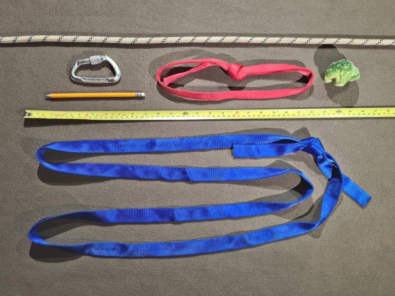

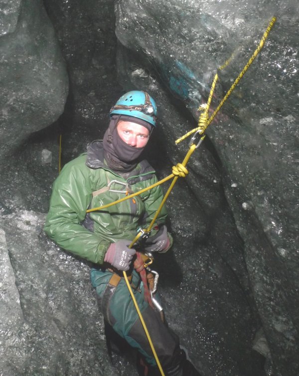
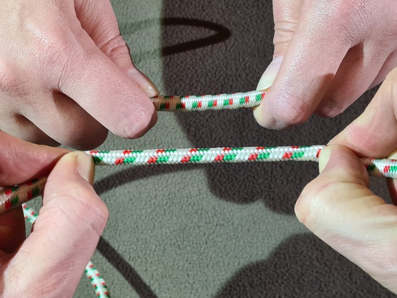
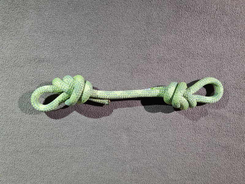
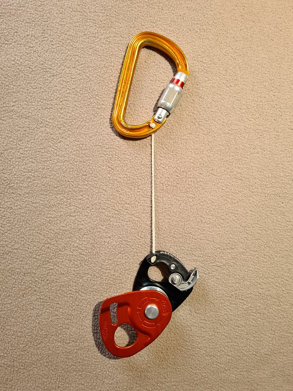
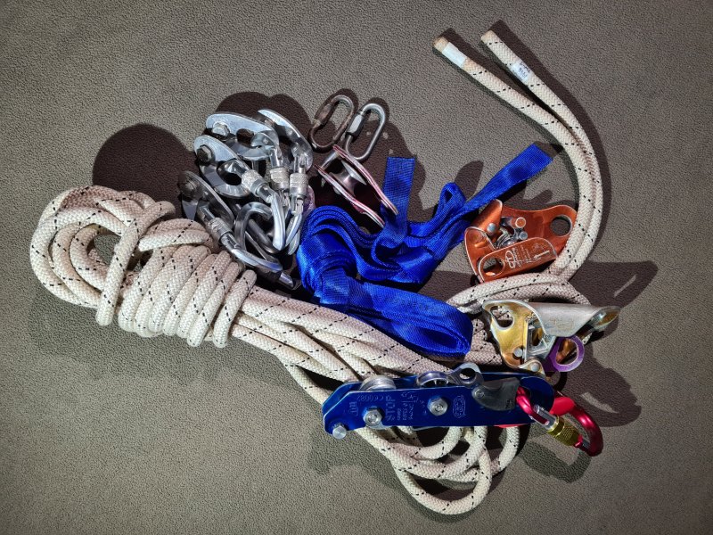
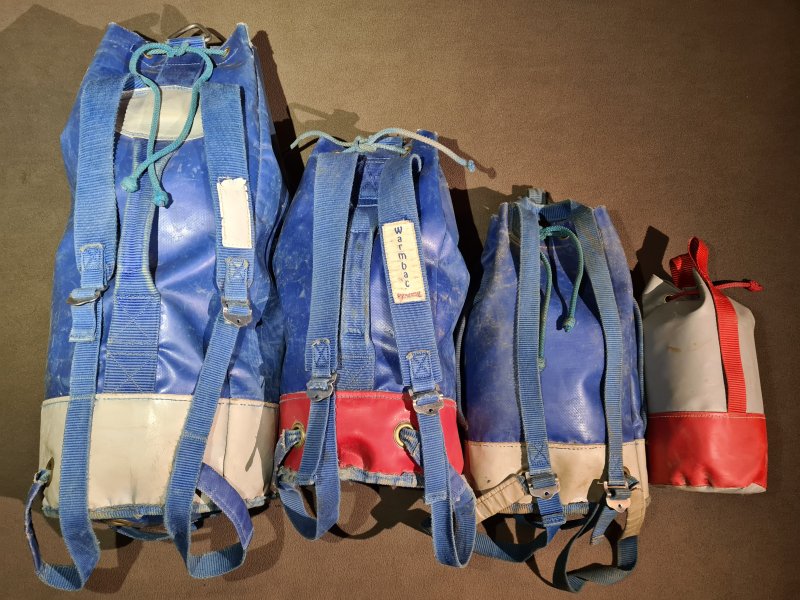
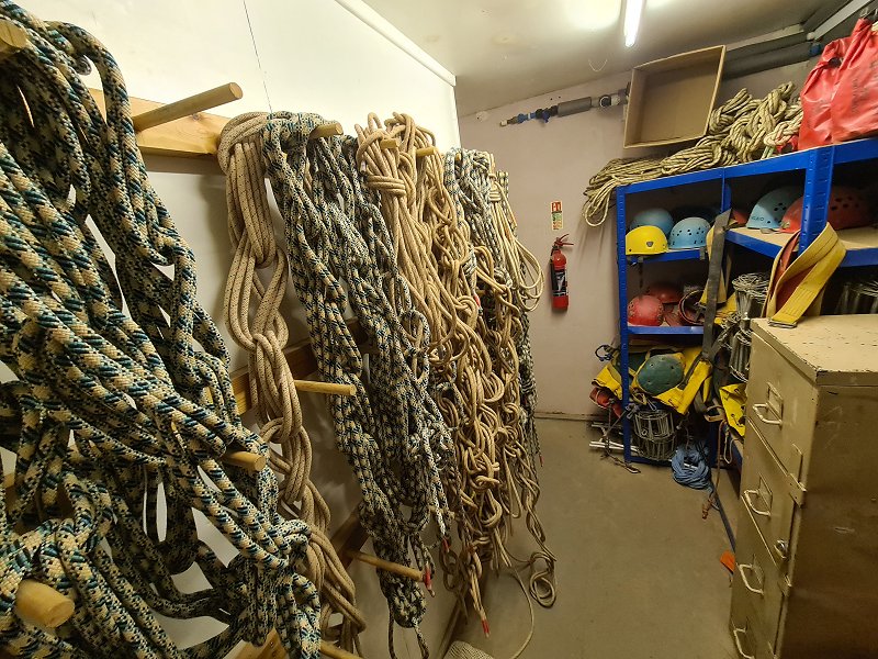
The strength of carabiners, maillons, ropes, slings and other SRT gear is specified in several different ways. Most PPE equipment will have its minimum breaking strength (MBS) specified, commonly called its breaking strain or strength. The equipment can be expected to hold at least that load, before it breaks. Often, it will be able to hold slightly more, sometimes a lot more (it is quite common for carabiners rated at 22kN to actually break at closer to 30 kN during testing). Individual items might be slightly stronger than others due to natural variances and imperfections in the material, but even the weakest one should not break at loads lower than the MBS. With most manufacturers, this is actually a statistical confidence of at least 3σ, meaning that 99.7% of items will not break at loads lower than the MBS. This means that out of every 333 devices tested, only one should fail below the MBS.
According to European EN PPE standards and international UIAA standards, several samples must be tested, often several representative samples from each batch of products, and none of the sample products that are tested are allowed to break at a lower amount than the MBS, when tested according to the standards. The standards may require ropes or metal pins of a certain diameter to be used when pulling on the product during the test, depending on what product is being tested. These may not match what will actually be used to connect to the sproduct in practice, so the results in practice may be different. Other national or international PPE testing requirements may allow a tiny percentage to fail lower than the MBS, but this is not allowed by any of the major international PPE testing standards.
However, after being subjected to loads significantly lower than the MBS, the equipment may be permanently deformed and no longer function correctly. For example, carabiners or maillons may no longer open and close correctly. As a general rule, no equipment should be intentionally subjected to loads above 20% (a fifth) of their MBS. This may be called their working load limit (WLL) or safe working load (SWL), and the ratio of the working load limit to the MBS, is called a safety factor (SF). At that load, they are expected not to become deformed, and should continue to function correctly. The actual safety factor might be different with some products, sometimes 25% (a quarter), 17% (a sixth) or 10% (a tenth) of their MBS, and manufacturers do not often state what factor they use.
With some equipment, particularly maillons, it is common to specify the working load limit in kilograms, rather than the MBS, and the safety factor is assumed to be 20%, so a maillon with a 400 kg WLL is assumed to have an MBS of approximately 2 tonnes. The ratings are typically specified in kilonewtons (kN), where 1 kN is the force experienced when holding a 101.9 kg load on Earth. For the sake of simplicity, think of it as 1kN being approximately 100 kg, and 10 kN being approximately 1 tonne (1000 kg). 22 kN is therefore approximately 2.2 tonnes.
The ratings are normally only for equipment that is being used correctly, such as the gate being closed on a carabiner, and the load only pulling in the correct direction. However, with carabiners, there will be separate MBS ratings for a incorrect usage as well. With some devices that can legitimately be used in numerous different configurations, such as rigging plates used for climbing (not caving), the MBS will typically apply to the weakest configuration. With ropes, the MBS is almost always specified for a rope without any knots in it. With some devices, such as belay devices and ascenders, the MBS is largely meaningless, since the devices may intentionally slip down the rope, or unintentionally damage the rope, at loads much lower than they would break at. As a result, these devices might only supply a working load limit.
It is worth noting that if a metal product (such as a carabiner) is loaded at nearly its MBS, then unloaded, and loaded again, it might break at lower than its stated MBS. The more times it is loaded at very high loads, the weaker it becomes. An aluminium carabiner with its MBS rated as 22 kN, might actually break at 30 kN if loaded just once. However, if it is loaded several times at 20 kN, it might eventually break at 20 kN, rather than 22kN or 30 kN. This effect is known material fatigue.
As shown in real testing with aluminium, when a carabiner is loaded to 85% of its MBS about 250 times, its strength will probably have reduced enough to snap. At 90% its full strength, only a couple of cycles could be enough to break it. The number of times it can be loaded increases dramatically as the loading level decreases, so that if it is loaded to 50% of its MBS, it takes about 3'000 cycles before it snaps. With loading up to 30% of its MBS (as much as it will normally encounter in a severe climbing fall), it takes over 10'000 cycles before it snaps. This number increases exponentially for lower loads, and with loads as low as those seen during SRT, the number of cycles should be into the millions (enough that no testing results are known because it would take too long to test). This effect continues for any loading level, and even the tiniest loads can cause fatigue effects, given enough cycles.
With steel, there is normally no fatigue effect at all for 40-50% of the MBS, and it can endure infinite loading cycles below those levels. Above the 40-50% fatigue threshold, steel products show exponential growth in the number of cycles for lower loads, but with a much higher endurance than aluminium. By 90% of the MBS, they can normally cope with a few hundred cycles, and by 70%, they can cope with 10'000 cycles or more. By 60%, they can already tolerate millions of cycles. Stainless steel follows the same pattern, but the fatigue limit is lower (the MBS is typically higher). Cyclic loads, fatigue and deformation are why it is important for carabiners and other metal devices to be rated at much higher loads than they will actually experience, and with the loads experienced during SRT, fatigue should not normally be the reason for retiring them, as they will have been retired for other reasons long before fatigue becomes an issue. However, aluminium carabiners used very frequently to catch high load falls, such as those used at indoor climbing facilities, will need to be periodically replaced.
All of these ratings are only valid for items that are new. Over time, abrasion, corrosion and material fatigue will reduce the strength.


A French company that makes rope working equipment, and pioneered many aspects of SRT. Within Europe, this is one of the largest SRT equipment manufacturers, and many cavers will have their entire set of SRT gear produced by Petzl. Insultingly called "pretzel", but some people are not aware of the joke and think you are stupid.
It should be noted that while Petzl is by far the best known European manufacturer, there are a great many other respected companies within Europe that produce similar equipment, often with each of the companies basing their designs on each other's. Some actually make them for others, and allow the other companies to brand the products as if they made it themselves. Examples include AustriAlpin and Stubai in Austria, Lanex/Tendon, Ocún, Rock Empire and Singing Rock in the Czech Republic, Aventure Verticale (AV), Beal, Edelweiss, Courant and Péguet in France, Edelrid and Salewa in Germany, Alp Design, Camp, Grivel, Kong, Raumer and Skylotec Outdoor / Climbing Technology (CT) in Italy, Fixe and MTDE in Spain, Mammut in Switzerland, and DMM, Heightec, ISC, Lyon Equipment, Marlow, Titan Climbing and Wild Country in the United Kingdom. Outside of Europe, there are a great many trusted equipment manufacturers, such as Black Diamond, BlueWater, CMI Equipment, Cypher Climbing, Glacier Black, Mad Rock, Metolius, Omega Pacific/The Weinel Group, Pigeon Mountain Industries (PMI), Rock Exotica, Seattle Manufacturing Corporation (SMC), Sterling Rope and Trango in the USA, Alpen Pass, Big Compra, For Rope, Safetec and Task in Brazil, and (to a very small extent) Kailas in China. Many others can be included when considering similar equipment aimed at rope access and arboriculture (Teufelberger in Austria, Cousin Trestec and FTC Tree in France, ART and Skylotec in Germany, Arbpro in Italy, 4SRT, Foin, Globestock, Harkie, Husqvarna, Stein and Treehog in the United Kingdom, 3M, Honeywell, Notch, U.S. Rigging and Yale Cordage in the USA, Pensafe in Canada), sailing or kayaking (Palm in the United Kingdom), and paragliding (Kortel and Supair in France, Finsterwalder & Charly in Germany, Woody Valley in Italy, Gin Gliders in South Korea). However, even within the USA, where it is common to use a mix of American brands, the market is still dominated by European brands, particularly Petzl.
Its founder French caver Fernand Petzl was one of the early users of many aspects of vertical caving originally, exploring the Dent de Crolles system in the Grenoble region of France since 1934, mostly along with French caver Pierre Chevalier and other pioneers. He was then among the first to use nylon ropes underground along with their inventor Pierre Chevalier in 1942-1943. By 1968, he was manufacturing SRT devices for sale, in his workshop, largely designs and devices created by French caver Bruno Dressler. The company was founded in 1975, and continued to produce devices based on the same designs.
This history section only covers Petzl. This article also has a detailed history of many of the other devices and techniques that are used for vertical caving.
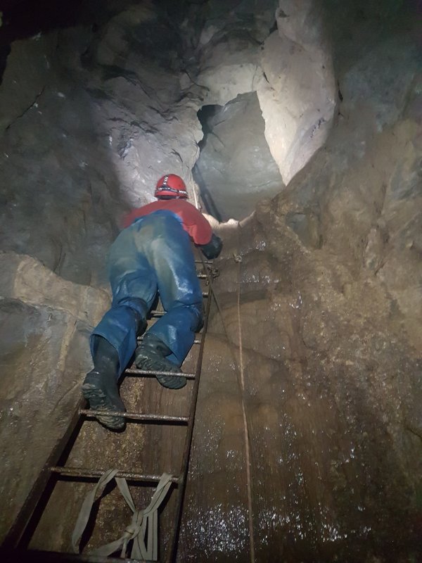
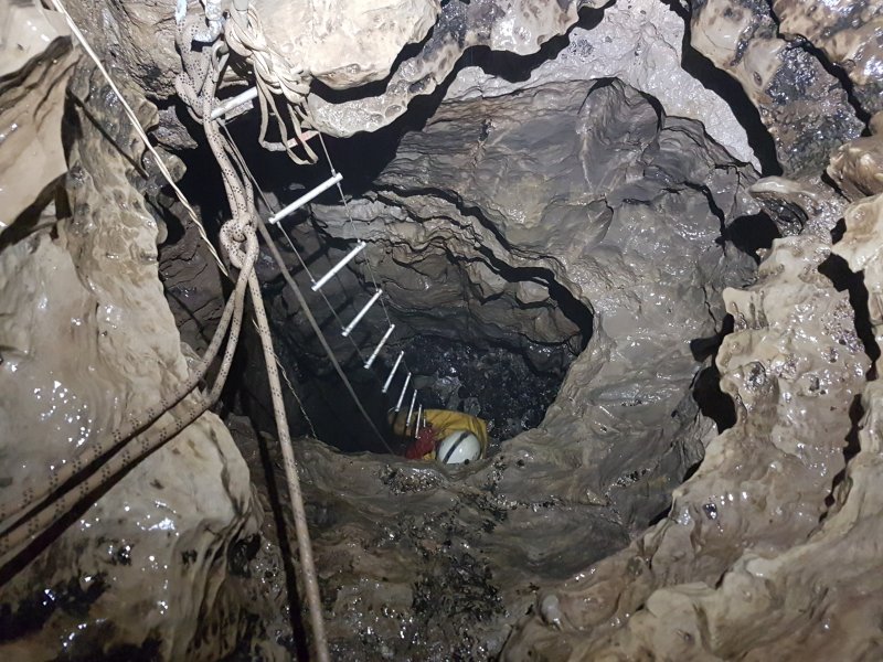
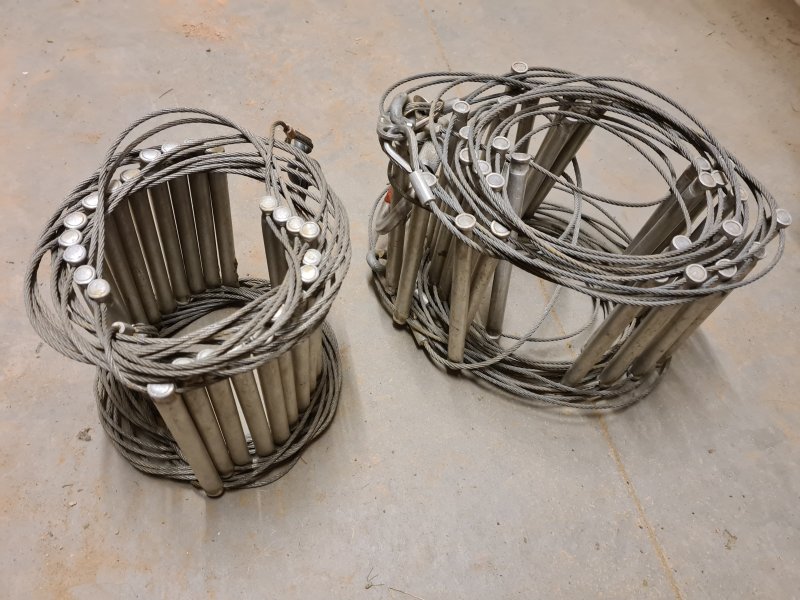
What it sounds like. Specifically an electron ladder, with the sides made from very thin wire that looks far too thin to support your weight, and rungs made from an aluminium alloy. These should always be removed from the cave after use, and not trusted if left underground, because the wires rust quickly. Electron ladders can be coiled up, and transported in and out of caves relatively easily. They are used in places where you do not want to carry in separate sets of SRT gear for each person, or in cases where people have not learned how to do SRT. Resists abrasion far better than a rope. Requires much more arm strength (very tiring on big pitches), and does not provide safety near a pitch head. Because the ladder is flexible, climbing on a free-hang involves hugging the ladder and holding it from the back of the rungs, and normally using one foot behind the rungs as well. Climbing over a rub point or up a sloping pitch can be very difficult, since your weight pulls the ladder against the rock. As a result, you may need to grip onto rungs with fingertips, or pull one side of the ladder away from the rock so that the rungs can be used. Although training is required to learn how to climb a flexible ladder, this is minimal compared with SRT. Requires a lifeline for safety while climbing, and this also requires training.
Most designs have small C-links on each end of the wires, so that ladders can be linked into longer ladders, or connected to a spreader or wire trace so that they can be attached to an anchor or natural. The links can also be used to attach thin carabiners. Some designs just have a swaged eyelet, and rely on maillons instead of C-links, since maillons are normally much stronger. To avoid damaging the ladder or reducing its strength, each side wire must not diverge more than 20° from perpendicular to the first rung, where it emerges from it, which is why a spreader or wire trace is used.
The minimum breaking strength of a ladder is somewhat complex. The wire used to make an electron ladder can usually hold 500 kg or more when new, but the exact amount depends on the wire that is used. As an example, 3 mm wire might hold 6 kN or 611 kg, and 4 mm wire might hold 10 kN or 1019 kg. The swaged eyelets at each end hardly reduce the strength at all, and the quoted strengths are given for wires with swaged eyelets. Since there are two wires per ladder, the overall strength could be assumed to be around 12 kN or 1223 kg for a ladder made with 3 mm wire. If C-links are used, the strength of a C-link becomes the weakest part of the wires, at around 2.5 kN or 255 kg per side, so the maximum strength is now 510 kg. The rungs are surprisingly strong, but their strength will depend on which epoxy or crimp has been used to connect them to the wire, how wide they are, where you stand on the rung, and how wide your boots are (which is why it is difficult to find the strength ratings for electron ladders). The rungs might grip the wires with a strength of 4 kN or 408 kg per side, so a total of 816 kg between both sides. The rungs themselves might hold 2.8 kN or 285 kg, when loaded at the middle of the rung over a width of at least 18 mm. In other words, you are not supposed to clip a carabiner directly to a rung, since it is much narrower than 18 mm. The rungs are designed for hands and feet, not carabiners. Assuming they are used correctly, this means that the weakest point of a ladder is the middle of a rung, at 285 kg per rung. While climbing, typically at least 2 or 3 rungs are used at once, so the ladder can hold more than 285 kg during normal use, but this reduces to 285 kg if you hang off a single rung with your hands. An electron ladder in good condition is easily able to take the weight of a caver, even if the weakest part has only a tenth the strength of a carabiner.
Manufacturers may specify a rated load, saying how much load they should be used with, rather than the load that they will break at. As an example, a ladder matching all of these strength measurements might have its maximum rated load listed as 100 kg for caving electron ladders or 140 kg for access usage, about half the weight that could cause a rung to break. This is to allow for the impulse forces that might be experienced as you move around on the rungs, for the unexpected forces at rub points, and for the extra load when multiple ladders are linked together. Manufacturers may also state that only one person should use a ladder at once, even if it might be strong enough to hold two people at the same time. These ratings are given by Lyon, one of the manufacturers that actually gives ratings for their ladders - thanks Lyon! However, it is worth noting that even if a ladder is tested and has strength ratings, flexible ladders cannot be considered PPE, and a lifeline is always needed for safety.
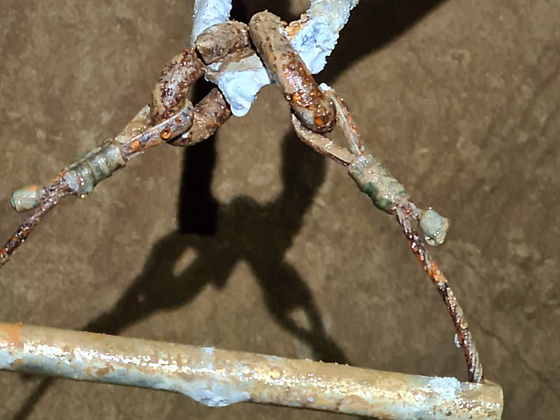
After being used for some time, wear and tear causes some strength of the wires to be lost. Rusted ladders lose most of their strength. From personal experience, with a ladder that had been left in a cave for years, where one strand had rusted enough to snap completely when someone tried to climb the ladder, the remaining strand looked rusted too, but two people hanging on it together could not snap it. In the end, it only snapped when two people spun around in circles on it, and caused it to twist severely then snap. The rungs did not fail. In many other cases, ladders left in caves for months or years have rusted to the point that the wires simply disintegrate, leaving the rungs scattered on the floor, holding on to tiny rusted stubs of wire. When rust sets in, it is almost always the wires that end up as the weakest parts of a ladder, even though they were originally the strongest.
Stone staircases were built in Tell Qaramel, Syria, around 11000-10000 BCE, Göbekli Tepe, Turkey, in 8950 BCE, and the Tower of Jericho, Palestine, somewhere between 9400 and 8000 BCE (none of which are ladders, but it helps to put things into perspective). The oldest known evidence of a ladder was found in a cave painting in Cuevas de la Araña in Valencia, Spain from 8000 BCE. The painting showed either a grass rope, rope ladder or liana vines being climbed by two people, to collect honey from a bees' nest (it is hard to tell exactly what is being depicted, since it is just three vertical lines with only a single potential rung, so perhaps it is best to leave the experts to argue about that one). The oldest known conclusive evidence of a rigid ladder was found at Çatalhöyük in Turkey, which would have been used to enter a house via a roof opening, thought to be from 6500 BCE. It consisted of a thick, wooden plank (like a railway sleeper), with a set of notches carved into it, which could be used as steps, like an extremely steep staircase. Depending on whether they are made from a round log or flat plank, these types of ladders may be referred to as notched log ladders, tree trunk ladders, notched ladders, monoxyle ladders, or chicken ladders by various authors, or Steigbaum or Steigbäume in German.
In Canada, the Keatley Creek settlement is often conjectured to have needed ladders to access pit houses (a shallow, circular pit with a conical roof of wood) via a hole in their roof, from 6000 BCE to 1000 CE. However, this conjecture is entirely based on relatively modern practice from the 1800s where notched log ladders or rope ladders were used, as if house construction has not changed for 8000 years. No supporting evidence of ladders has actually been found at the site, or any other prehistoric sites where the same conjecture is used. A notched log ladder made from half a log was found at the 跨湖桥遗址 (Kuahuqiao) site near 上海市 (Shanghai) in what is now eastern China, dating from the site's main phase of occupation in 5800-5450 BCE. In 4050 BCE, the 河姆渡文化 (Hemudu culture) used a log ladder at 田螺山 (Tianluoshan) nearby. This same type of ladder remains in use in the Tibet region, but usually leaning more gently to become an actual staircase. Another cave painting in Barranco Gómez cave in Sistema Ibérico, Spain, from around 5500 BCE shows a rope ladder (likely to have been made from grass) being climbed to collect honey from a bees' nest. The ladder's structure is very clear, with chained loops of rope used as rungs, the ladder being connected at its top, and reconnected to the rock part way down using a pole. The person climbing it is shown hugging the ladder, the most appropriate way to climb a rope ladder.
There are several examples of stone age people creating large buildings with upper floors and a tall roof that would have been difficult to construct or access without some form of structure to climb up, such as the Linear Pottery Culture from 5500-5000 BCE in central and eastern Europe, and the Cucuteni-Trypillia culture from what is now Moldova, Ukraine and Romania in 4800-3000 BCE. Both of those cultures originated from multi-generational migrations out of Turkey, so knowledge of log ladders can possibly be assumed in those cases. However, it is extremely rare for excavations of stone age sites to produce any evidence of ladders, presumably due to poor wood preservation. While ladders are often conjectured to have existed at many sites, stone age people could have used earth or log ramps instead of ladders, or sloped the roof enough to walk up parts of it, perhaps using ropes for assistance, or leaned a branch against it and walked up that instead of using a purpose made ladder (the way some African huts, even multi-storey huts, are still made). While the multi-generational migrations from Turkey eventually reached Britain by 4100 BCE, there is no known evidence that they initially brought knowledge of ladders with them. Although there is a common conjecture that European neolithic houses could have used notched log ladders, there is no known evidence of them in European sites, and all of the conjecture relates to the same article, which appears to have no supporting evidence to back up the claim.
Neolithic ladders may have been found at lake dwellings (built on stilts like a Celtic crannog, but in shallow lakes not on artificial islands) in Europe. At the Lagozza site near Besnate in what is now northern Italy, a tree-top trunk with its branches cut into short stumps is thought to have been a possible ladder, dating from about 3600 BCE. At the Schaffis or Chavannes site near Biel in what is now Switzerland, which dates from 3171-3118 BCE, a pole was found with regularly spaced holes in it, about 30 cm apart. This could just as easily have been part of a fence, but was declared as being a single pole ladder by an archaeologist in the late 1800s. No other parts of it were found to prove its purpose. Egyptians were using rigid ladders very similar to a modern wooden ladder, known as pole ladders by archaeologists, to scale Canaanite city walls during sieges from at least 2400 BCE. One depicted in the tomb of Kaiemheset was shown with wheels so it could be easily moved, and one from the tomb of Senedjemib Inti was shown without wheels.
Ladders feature in many religious scriptures and stories, and while the dates that the stories first appeared is not known, the dates that they were written can be used to show that ladders were in use at that point. There are stories about Chinese legendary 神農 (Emperor Shennong) who supposedly lived from 2737 to 2697 BCE and used a rattan (liana) ladder to climb a mountain. There are other stories about Chinese legendary 帝舜 (Emperor Shun) who supposedly lived sometime between 2294 and 2184 BCE and used a ladder to get onto a roof. However, the stories were not written down until some time before 296 BCE in the earliest case, and are very unlikely to have any basis in historical fact (especially since Shennong's ladder supposedly transformed into a forest). Rigid ladders were described in the pyramid texts of Egyptian pharaoh Unas, in approximately 2315 BCE, as ladders were thought to carry the soul to the afterlife, and might be left in the tombs for the dead pharaoh to use. Pharaoh Pepi II's pyramid texts specifically mention rope ladders and rigid ladders, at around 2185 BCE. Hebrew religious texts mention ladders at approximately 1779 BCE (specifically Jacob's Ladder), though the story itself was actually written around 1000 years later. The story is almost certainly derived from the Egyptian ideas about ladders being used to reach the afterlife.
Harrow Hill, Cissbury Ring and Grime's Graves are late Neolithic flint mining sites in Britain, each with hundreds of mine shafts from 6-13 metres deep, dating from 4000-2200 BCE, 4000-3500 BCE and 2650-2300 BCE respectively (Harrow Hill has some slightly older open cast pits). The common conjecture is that ladders would be needed to access the mines, most often suggested as being made from a tree trunk with notches cut into it as a log ladder (depicted and described by English Heritage's own information). An alternative suggestion is that rope ladders made from plaited leather with wooden rungs could have been used, hung from trees placed over the shafts. (The conjecture was made because of evidence that a beam was placed over one shaft, and grooves at the start of passages that were not where a ladder could have been, both of which suggest hauling the flint using ropes, not ladders.) However, there is absolutely no supporting evidence for either of these approaches, and no evidence that suggests either type of ladder were known in Britain in the Stone Age. In fact, the only ladders known in Britain are much later, and of too low a quality to be capable of reaching the depths needed, suggesting that there had not been any more advanced ladders in use during the Neolithic. Shorter lengths would have needed several intermediate platforms for such deep shafts, but there is no evidence of notches/sockets or postholes for platforms. 15 metre tree trunks would have been very challenging to remove afterwards, lifting at least 0.5-1 tonnes of wood vertically upwards until it towers vertically overhead twice as high as the tallest known (not exaggerated) Neolithic wooden structures in Britain. Even thicker wood would probably have been needed to avoid snapping them at the weak notches during the removal process, so they would have been even heavier. If they had been used, it would have been far easier to make a new one for the next shaft instead of trying to reuse an old one, but no remains or traces were found abandoned in the shafts during excavations (some had burned fireplace wood in passages used for flint knapping while they were active). Even ignoring the fact that the depictions usually show far thicker trunks weighing over 2 tonnes, the whole idea is unlikely, given the lack of supporting evidence. From 1900-1300 BCE, the Kargaly copper mines in Russia were worked by the Srubnaya Culture (Indo-Iranians) for copper, using shafts as much as 12 metres deep to access the mines. Some shafts have notched footholds dug into one wall that can be used as a ladder.
The oldest ladders in Britain are a series of notched log ladders found in water holes and gravel pits, with one from Fengate at Flag Fen near Peterborough in The Fens dating from 1767-1411 BCE (IntCal 20 calibrated) and one from Yarnton in Oxfordshire dating from 1750-1570 BCE in the early bronze age. Knowledge of their construction could have come from one of the recent Bell Beaker migrations from continental Europe at the end of the Neolithic, or from the British Wessex Culture bronze age trade with the Armorican Tumulus culture in northern France and the Hilversum culture in northeast France, Belgium and the Netherlands. Others include one from Bradley Fen at Flag Fen dating from about 1650-1460 BCE, one from Pode Hole Quarry near Peterborough probably dating from 1520-1400 BCE, two from the middle bronze age (1500-1100 BCE) at the Imperial College site at Harlington in London and the Cleevelands site at Bishop's Cleeve in Gloucestershire, several from the middle bronze age at Needingworth Quarry near Cambridge, two from 1390-1110 BCE at Brigg's Farm near Peterborough, one from Bar Pasture near Peterborough dating from 1316 BCE, and one from 1263-1114 BCE in Bucklers Park in Berkshire. The Peterborough ones are about 57 km from the Grime's Graves site. Several more examples have been found in southern England all the way up to the Roman era, and the Bucklers Park one is considered long at 2.3 metres, while a 2.4 metre example from 525-457 BCE is considered exceptional. It is likely that there are older ones too, but the details are missing or hard to find, and often behind expensive paywalls. It is worth noting that in spite of there being numerous excavated Neolithic sites where wood has been preserved and where a ladder would have been useful, such as marsh trackways, crannogs, docks, gravel pits and mines, and in spite of numerous Neolithic wells having been excavated, there is no evidence (at the time of writing) of any Neolithic ladders in Britain. Two notched log ladders were found in San Lorenzo a Greve in Tuscany, Italy, dated to 1616-1464 BCE and 1440-1400 BCE.
Egyptian mining took place in mines with short, vertical shafts, particularly on the Sinai Peninsula, somewhere between 1550 BCE and 1069 BCE. The methods used to climb those shafts is not known, and it could have involved ladders, ropes or chimneying, but the absense of trees on the peninsula makes ladders less likely. Hitite carvings from Turkey show rigid ladders being used by acrobats some time after 1400 BCE. Various notched ladders, typically made from thick planks like the Turkish example from Çatalhöyük, were found at Mitterberg mines in Austria, in the Mühlbach part of the site. The ladders themselves were not dated, but analysis of wooden artifacts from the nearby Troiboden part of the site show two periods of activity between 1380 BCE and 1275 BCE. This is the earliest known use of notched ladders in mining. They had a width of 17-22 cm, made from the trunks of fir trees. The steps were between 32 and 55 cm apart, and were originally notched about 7.5 cm deep, leaving only about 5-7.5 cm of wood for strength. The three longest were 1.7-1.89 metres long, and if leaned at an angle of about 30° from vertical, they could only climb about 1.6 metres per ladder in the best case. The suggestion was that the ladder could be placed on a cairn to get more height, but that only works when starting from ground level. However, their forked ends could be placed over a stemple to gain height more effectively. They could be used to ascend shallow mines directly, but are thought to have been used to climb up to higher platforms, perhaps even climbing a shaft in stages that way.
An 8 metre long, 1.2 metre wide wooden staircase was built in the Christian von Tuschwerk mine at the Salzwelten Hallstatt salt mine site in Austria in 1344 BCE, and was surprisingly well preserved by the salt. It was constructed in the format of a wooden ladder laid onto a slope, with the gaps filled in with rubble and planks to create roughly flat steps, though the rungs were not fixed to the sides. It is therefore likely to be one of the first staircases to be used underground (and also predating most ladders, except for the ones left in the tombs of Egyptian pharaohs, and the ones in the Mitterberg mines). It is worth noting that this is the area that later gave rise to Celtic culture. Free-standing staircases, connected only at the top and bottom, were also used in the Christian von Tuschwerk mine, and the later Grünerwerk and Appoldwerk mines which were also at Hallstatt. These are not really ladders, but actual staircases, with roughly flat steps (slightly angled backwards to catch the mud and avoid slipping), attached to side panels, like a regular staircase. They could be walked up rather than being climbed like a ladder. The dates of these constructions is not given, but they are from around the same time as the staircase that was made on the slope. Notched ladders were also used at Chinflon mine in Spain 1138-892 BCE. At Derrycarhoon mine in the Republic of Ireland, basic branches had been used in 1378-1119 BCE. A notched ladder found in one of the mines was not dated, but was presumably from a later phase, and another mine had activity in 1114-921 BCE, suggesting that the ladder might be from that time. They were then used in Roman times in Mavrovouni mine and Skouriotissa mine in Cyprus, Rošia Montană mine in modern Romania, Coto Fortuna mine in modern Spain, and Aljustrel mine in modern Portugal. It is not known whether the knowledge was passed from one site to the others, or whether they each reinvented the idea.
The more normal pole ladders with rungs were used in Britain from the late bronze age (nominally 1200-700 BCE for southern Britain), with a well built one dating from 1109-922 BCE discovered at the Cambridge Biomedical Campus, which had been used to access a well. It had separate side poles, and rungs attached using mortice and tenon joints, a construction that had become much more easy with metal tools in the bronze age. This is so old that it pre-dates Celtic culture, and knowledge of the construction method could have originated from the late bronze age trade and migration of Atlantic Bronze Age people from what is now France. Another one was found in pieces next to a fenced well in Wretham, Norfolk, but the age was not properly established before it was accidentally destroyed. It probably dates from the late bronze age. (A possibly related crannog 1.5 km away is likely bronze age, with dating based on a bronze palstave axe or "celt". Assuming it is the axe recovered from a private collection 30 years later, it is a middle bronze age design with variants still seen in the late bronze age. It was first mentioned in a later excavation memoir without saying exactly where it was found, and it could be unrelated. In addition, while pile trackways existed earlier, pile dwellings like crannogs are not recorded in England until the late bronze age. Numerous cleanly sawn bones found at both sites suggest late bronze age or iron age. Earlier shallow cutting of bone has been mentioned as "sawing", but sawing cleanly through a bone was unusual before the late bronze age, and far more common in the iron age.)
In the Book of Odes by 孔子 (Confucius), poem 241 - possibly written as late as 476 BCE - states that Chinese 周文王 (King Wen of Zhou) used ladders during a battle that took place in 1051 BCE. The Chinese are likely to have been using bamboo ladders at some time around then, but there is no historical record of when they were introduced to China. The Assyrians started to use siege ladders after 900 BCE. The Chinese started to use wheeled siege ladders called cloud ladders some time after 475 BCE (with their invention attributed to 鲁班, Lu Ban, another deity figure). Chinese ladders often would be made from a trunk with small pegs stuck into it, but cloud ladders would also use normal pole ladders with two poles.
Greeks were using presumably solid siege ladders during the siege of Πλάταια (Plataea) in 427 BCE, as written by Θουκυδίδης (Thucydides) in the Ἱστορίαι (History of the Peloponnesian War) in 431-404 BCE. Greek military instructions written by Αἰνείας ὁ Τακτικός (Aeneas Tacticus) in about 356-346 BCE included the mention of rope ladders and nets meant for catching animals, which could be climbed. Knowledge of their construction almost certainly originated in Egypt, and this particular mention was before the Roman conquest, so the knowledge would have then passed to the Romans, who could spread the idea throughout Europe. Given the constructions that would later be seen in Roman-occupied regions such as the Holy Roman Empire, it is almost certain that the rope ladders were made with rope sides and solid rungs, but the drawings are too poor to tell. The Ancient Greeks had almost certainly been using siege ladders long before then, as the Ἰλιάς (Iliad) by Ὅμηρος (Homer) described climbing over a fortified wall in 750-700 BCE.
In Britain, two other pole ladders were found dating from the middle iron age (400-100 BCE), used to access shallow wells in Milton Keynes and Bedfordshire near St Neots. The one from Milton Keynes had wooden wedges to jam tenons into their mortice where needed. Information about these early ladders comes from "Waterlogged wood analysis report, Milton Keynes East, Land North East of Milton Keynes, Area 18 (EMK1471)", Michael Bamforth on behalf of Pre-Construct Archaeology, March 2023. A few other examples date from around the start of Roman contact in 50 BCE, all using the same construction, and almost all found in wells and pits. One of them was found in Hull in Northern England, and measured 3.4 metres in length. Evidence was also found from Celtic villages and crannogs on lakes, such as the Glastonbury Lake Village in Southern England, where they would presumably have been used to access the settlement from a boat. Very few sources publish the dates for these ladders, but surviving clues indicate that it was from the late iron age, shortly before Roman occupation. Two used a wedged peg through a hole in the tenon to pin the joints in place, a technique which had been used in 5099 BCE in what is now Germany, for lining a well. It may be called a tusk joint or tusk tenon in modern woodworking. One Scottish example from Dumbuck Crannog was made from a single tree trunk, with the sides and rungs carved from it in one piece. It is the longest known early British ladder that is not Roman, at 4 metres long (with rungs only for about 3 metres of that length), and dates from around 200 BCE to 200 CE. It is the only known ladder to have been found at a Scottish crannog, while none are known from Irish or Welsh crannogs, in spite of dozens of excavations. In the middle iron age, there was a substantial increase in cultural exchange with continental Europe, as well as some level of migration, particularly from the Gaulish Celts from northern France, which probably explains where the increased knowledge of runged ladders came from, and the British Celts then spread the idea further around Britain.
Deneholes were 10-40 metre deep bell pit mines used to mine chalk in Kent and Essex in southern Britain, while minimising the damage to the surface land. Their use started before the Roman conquest in 43 CE, and continued until around the late 1300s, with only minimal changes in the approach used (later versions used different approaches). Their most active use was around 1225, when permission was given for every man to have a chalk (marl) mine on his own land. In many cases, notched footholds were dug into one wall (like at Kargaly) or opposing walls of the shafts, to allow them to be used as a ladder to access the mine. This approach is still used today with some caves, particularly when the entrance is lined with concrete rings, where holes are notched into the concrete. Roman mining was most likely to have used ladders, and although there is no conclusive evidence of exactly when the practice would have started, the Romans were actively mining with highly technological approaches, between 100 BCE and 200 CE. Runged ladders became far more normal in Britain after the Roman conquest of 43 CE, and one from 43-100 CE in London measured 5.6 metres in length.
Rope ladders are thought to have been used by Jewish people to access various caves around the Dead Sea in what was then Judea or the Roman Empire, now Israel and Palestine, starting from before 68 CE, where they then hid the Dead Sea Scrolls. The Cave Of Horror is thought to have needed rope ladders when it was accessed between 132 and 135 CE. However, there is no actual evidence for this, and the caves may have been accessible without needing any ladder or rope in the past simply by following animal paths, while the landscape could have now changed to require equipment. This is especially likely given that a burial from 4000 BCE was found in the same cave, and climbing a ladder while carrying a body would have been prohibitively difficult. Ladders are not thought to have been used inside the caves themselves. In 160-215 CE, a Roman carving called the Torlonia relief showed ships in a port. One of them clearly has a rope ladder with rope rungs, with a sailor climbing it. Another was clearly depicted in a Tunisian mosaic during Roman occupation in about 200 CE. The same approach was still being used in Venice in the 1200s. The fortified tower of Castell de Tona built before 889 CE in Francia (now Spain), and fortified towns of Sos del Rey Católico and Boltaña, both built around 975 CE in the Kingdom of Pamplona (now Spain), had no access doorways, and the conjecture is that rope ladders were used. However there is no evidence of what approach was actually used.
In about 950 CE, the manuscript Parangelmata Poliorcetica by Heron of Byzantium (now Turkey) included several illustrations that almost exactly match the instructions written 1300 years earlier by Αἰνείας ὁ Τακτικός. The hunting netting is clearly visible being used as a ladder, while the rest of the drawing appears to show climbing using spikes rather than a rope ladder, but it has faded too much to see, and clearer illustrations also depicted solid wooden siege ladders. Since some time before 1152, Burg Berwartstein, a castle in the Holy Roman Empire, now Germany, was accessed via a natural cave that passed part way up the underlying sandstone cliff. This was later extended by invaders using fire setting to almost reach the castle. There is frequent modern conjecture (often written as if it were a proven fact, but without any apparent evidence) that it initially had a rope ladder to allow access that could be removed to stop invaders, with a myth about a lone soldier protecting it with hot oil, but a rope ladder would be utterly impractical for bringing supplies and for the movement of armed soldiers. Historical analysis has stated that it is more likely that it actually had a staircase built in it. As early as 1284, the British Seal Of Dover showed that rope ladders were being used on sailing ships (the rungs are not visible, but the structure is clearly the parallel rope ladders of old ships), something that had not been seen on the Norman Bayeux Tapestry in the 1070s.
In 1313 or 1314, rope ladders were used with grappling hooks by William Francis and James Douglas, during the capture of Roxburgh Castle in Scotland, something that was later repeated at Edinburgh Castle. In 1321-1337, the Scaligeri princes of Verona were modifying a cave called Covolo di Butistone in Verona, now Italy. It was being used as a fortress, rather than for active cave exploration. They mined rooms, which needed a ladder to get between two of the floors (though it is possible that the upper rooms were added by later users of the fortress). It is assumed that they used one, and conveniently, their coat of arms features an image of a rigid siege ladder, so it is highly likely that they did. While it is likely that rigid ladders were used in caves by various people over the years to mine guano or collect birds' nests (likely bamboo structures in southeast Asia, as early as the year 800), or to explore caves that were found during mining operations (when Pen Park Hole was discovered in Britain in 1669, it was assumed that it had been found and explored by miners some time in the early 1600s, but there is no actual evidence for this), the dates of that are not usually known, so this section largely covers only active cave exploration as a sport. There is a suggestion that the Chinese might have been using rope ladders in caves in the 1300s or 1400s, but there is no verifiable source for this, and it is likely to have been just one person's assumption, rather than actual fact. Miners in general used rigid ladders, constructed from stemples or other solid structures.
An artistic French carving known as The Assault On The Castle Of Love from 1325-1350 clearly shows a rope ladder with rungs made out of rope, being used to climb a castle wall. Rigid ladders and rope ladders were used by monks to get between caves and platforms that formed their monasteries at Meteora in Greece, from as early as 1356, though the exact dates for their use are not known. They were recorded clearly as being used extensively, in an engraving in 1782, but the monasteries were founded in 1356, and would have needed ladders for access. It is also possible the hermit monks had used them previously in the mountains in the 800s CE, and lower caves after 1000 CE, before the monasteries were built. Bellifortis, a military manuscript written by Konrad Kyeser between 1402 and 1405 in the Holy Roman Empire, now Germany, depicted normal rope ladders with solid rungs, one of the earliest unambiguous depictions known in Europe. Numerous clever ladder designs (click "Verso"), including several rope ladders, were depicted by Leonardo Da Vinci in 1486 in Codex Atlanticus in the Holy Roman Empire, now Italy. Several of these have since been used for caving, including ladders made from a knotted handline, though mostly through reinvention.
The oldest verifiable evidence of a rigid ladder being used in a cave is from 1656, where rigid wooden ladders were being used by tourists in Baumannshöhle in Germany, before it later became a proper showcave. This can be seen in a sketch survey of the cave made by visiting student Von Alvensleben in that year (though the drawing is particularly difficult to interpret, and it does not look much like a ladder). The first known use of rope ladders for cave exporation purposes is from 1673 in Greece, when French ambassador Charles-Marie-François Ollier, Marquis de Nointel, along with Turkish sailors and officers (including Cornelius Magni, who wrote about it) explored the Σπήλαιο της Αντιπάρου (Cave of Antiparos), using rigid and rope ladders with lifelines, which were procured from the ship they were sailing in. The cave included a 23 metre pitch. In 1669 British captain Samuel Sturmy and his team including a miner named Dick explored Pen Park Hole, using a rigid ladder to climb up into a side passage. One notable British exception where rope ladders were well documented in mining is Lamb Leer Cavern, where British geologist John Beaumont had miners construct a rope ladder in 1676 so that they could more easily access the Great Chamber for mining. The report sounds like exploration was done without needing further assistance, suggesting that rigid ladders were used. In 1717, French botanist Joseph Pitton de Tournefort revisited Σπήλαιο της Αντιπάρου, using ladders of an unspecified kind. In 1760, British coal miners John Rathbone, Abraham Scott and William Bryant descended Pen Park Hole, with Alexander Catcott descending the first part. They probably used ladders, but the method is not recorded. Further exploration took place during the next few decades. In 1765, British miners were described as using stemples as ladders with very widely spaced rungs, manually climbing the stemples with hands and feet. It is not known when this practice started, but it is likely to be very old, and is one of the methods thought to have been used in Peak Cavern in places like Stemple Highway and Leviathan, as much as 80 metres off the floor.
Historically, use of rope ladders was the main way for cavers to descend and ascend pitches, and wire ladders are still regularly used in cases where a cave has just a couple of minor pitches, but they have been largely replaced by SRT in potholes. They partially took over from the earlier use of handlines and winches on pitches, but did not replace them completely. Ladders were originally handmade from knotted hemp rope and wooden rungs, and during the early era of their use, they were often made specifically for an individual caving project since they did not last very long. As far as sport caving is concerned, Grotte des Demoiselles in France was explored using an 18-20 metre rope ladder modelled on sailing ladders, by Benoît-Joseph Marsollier and two others in 1780, descending a 15 metre pitch. This was repeated with better rungs made from iron. French researcher Jean Marie Amelin used wooden rungs in 1821, to reduce the weight, used in the same cave. Spanish caver M. Sola used a rope ladder with wooden rungs in Les Coves de Montserrat in 1825. In the 1830s and 1840s, a rigid wooden ladder was used at Dr. Bannister's Handbasin in Long Churn Cave in Britain, for tourists to use on guided wild cave tours. In 1835, Croatian school supervisor Julije Fras wrote that locals from Petrovo previously used a 1.5 metre wooden ladder to obtain water from Barić's Cave, which he also visited. In 1838, Gorin's Dome was discovered in Mammoth Cave, Kentucky, USA, by Franklin Gorin and Stephen Bishop. Reaching it required ascending a ladder (therefore presumably a rigid ladder, not a rope ladder), which was still in use in 1866. They made extensive use of rigid ladders during exploration, lowering a rigid ladder down a pitch to descend it, and using a rigid ladder as a bridge to cross a pitch, finding Mammoth Dome via an ascent in 1840. In 1839-1840, Italian/Austrian mining engineer Antonio Federico Lindner had miners from Idrija blast open several narrow shafts of Grotta di Trebiciano (then the Austrian Empire, now Italy), installing wooden platforms separated by rigid wooden ladders, as they would have done while mining. At 250 metres depth, the miners discovered a new 30 metre pitch, which they descended without Antonio Federico Lindner using rope ladders with wooden rungs, setting a new depth record of 329 metres in 1840. Propast Macocha (Macocha Abyss) in the Czech Republic was explored using "folding" ladders, which could be joined together to reach the required 60 metres length, by Eduard Hanke von Hankenstein in 1856. The exact design is not known, but it is likely to have been a rope ladder, since the 45 kg weight is about right.
In 1870, British cavers John Birkbeck, William Metcalfe, William Boyd Dawkins and a party of seven other men and three women descended Alum Pot using a winch, installing ladders (thought to be rigid wooden ladders, but this is not recorded) on the lower pitches. American showcaves started having rope ladders installed for tourists, but it is not recorded whether these were used during actual caving activities. In 1880, British miners Andrew Lyons and two others had rediscovered Lamb Leer Cavern, and installed rigid ladders in the shaft, and another part way through the cave used to access it. These were then used in 1882 by foreman Joseph Nicholls and several other visitors, including a newspaper reporter, when another rigid ladder had been added to reach an upper passage. The same ladders were used by cavers for decades afterwards. Kačna Jama, then in the Austrian Empire, now Slovenia, was explored by Austrian Anton Hanke, and Slovenians Gregor Žiberna-Tentava, Valentin Rešaver and Jožef Rebec in 1880-1891. They used fixed ladders for part of the descent. Rope ladders were installed for tourists in Cave Of The Winds, Colorado, USA, possibly as early as 1881. A "ladder" made from a tree trunk with branch stumps to use as steps was used in 1883 by William McCardell, Tom McCardell and Frank McCabe to explore Banf Cave hot springs, Canada. Rope ladders were then installed in Lehman Caves in Nevada, USA, for tourists to use in 1885, but that is not how the cave was originally explored. The use of rope ladders for cave exploration was popularised by French caver Édouard-Alfred Martel, whose first use of them was in Abîme de Bramabiau in southern France in 1888. He subsequently explored many other caves using rope ladders, such as the Gouffre de Padirac in 1889, as well as some using rigid wooden ladders. He was also one of the first to use a wire trace for attaching a ladder, but the date of that is not known. Between 1889 and 1892, he used a ladder to provide something to hold while suspended from a winch, to stop himself from spinning around.
Wire ladders were first used in Alum Pot in Britain by Harold Dawson in 1894, but these seemed overly heavy, as one person could only carry a 4 metre length, and they were then clipped together with dog/trigger clips. The rungs are not stated, but may have been wood or steel. However, most cavers still used hemp and later nylon ladders for the next 65 years. Édouard-Alfred Martel used a rope ladder to descend Britain's famous Gaping Gill in 1895. During the descent, the ladder had not been long enough, and he had to manually climb a rope for the top 20 metres! British caver Edward Calvert had been planning a descent of Gaping Gill using rope ladders in 1895, but missed out on the glory due to delays. The Yorkshire Rambler's Club descended Long Kin West in 1896 and Rowten Pot in 1897 using rope ladders. At that time, some ladders were made with wooden rungs, and some were made with rope rungs, which were lighter, but trapped the feet more. Some had occasional wooden rungs with rope rungs in between. Rope rungs very quickly lost favour, and wood was almost exclusively used. Cavers had developed the semi-standard climbing calls during these years. Many clubs started to build ladders that could be used by their members, and the ladders would survive enough trips for that to be worthwhile. American teenager James Larkin "Jim" White used a ladder that he made from rope, fence wire and local shrubs to explore Carlsbad Caverns, New Mexico, USA in 1898, an event which he subsequently repeated with a Mexican teenager known as "Muchacho". New explorations in the cave used rope ladders in 1924. Ladder usage started to spread to other British caving regions, such as being used extensively in 1903 in Mendip, by Ernest Albert Baker of the Kyndwr Club from Derbyshire, and Herbert Ernest Balch from Mendip. Some of the ladders used in Britain had metal rungs by 1910. Wired aluminium ladders were used by Vladimír Brandstätter in Propast Macocha-Punkevní Jeskyně (Punkva Caves) in 1924, and since it was a showcave at that point, they are likely to have been very thick cables and rungs.
Robert de Joly invented the Galet, a device to push rope ladders away from rub points to avoid damage to the hemp, in France in the 1920s. French cavers typically used naturals to attach ladders, but in 1924, French caver Henri More and members of the French mountaineering/caving club Les Jarrets d'Acier used a log cut from a tree trunk as an anchor. They then used pitons somewhere between 1924 and 1932. Hemp ladders were painfully heavy, about 1 kg per metre. The hemp used in rope ladders absorbed water, and became very heavy, and would occasionally snap without warning (though this did improve over time). Italians had experimented with using wire ladders with C-links later called the "Italian link", some time before 1930. The ladders were heavy due to being made from thick cables and rungs that were far stronger than they needed to be. The C-links were then used by other cavers. Using aircraft cables, and metal inspired by World War I incendiary munitions (La Spéléologie, Robert de Joly, 1947), Robert de Joly invented the electron ladder in France in 1930, and they weighed just 40-100 grams per metre (modern ones are 60-120 grams per metre). This is very similar to the weight of a 10 mm nylon rope, but ropes soak up water. A ladder still needed a lifeline, potentially twice as long as the ladder, so electron ladders and nylon ropes would be about a third of the weight of a traditional hemp rope ladder, or a fifth the weight of a hemp rope ladder and lifeline (though it would be another 12 years before nylon would be used to make ropes). However, British cavers preferred rope ladders, with rigid ladders and a proposal for a stronger ladder made from chains in 1936-1937. Cavers took a long time to trust electron ladders due to how thin they looked and how easily they moved around due to the lack of weight, so their first use in Britain was in 1943 (Forty Foot Pot, Swildon's Hole, by the Bristol Exploration Club). It is also worth noting that even 3 mm steel wire was stronger than the thin mountaineering ropes that were used to make rope ladders at that time, though wooden rungs would typically be stronger than the rungs of an electron ladder. When beech rungs were tested on a newly built wooden rope ladder in Britain's Ogof Ffynnon Ddu in about 2000 (yes, really), which were attached to a rope using a nail driven through the rung and rope, they held 300-400 kg without breaking or slipping, but their actual strength is not known and could have been higher. With electron ladders, the lack of weight meant that cavers had to learn a completely new climbing technique, hugging the ladder as we still do today. The name comes from the Elektronmetall alloy that the rungs were made of, which was manufactured by the Brittish company Magnesium Elektron. The first British electron ladders were built by Harry Stanbury of the Bristol Exploration Club in 1943.
In 1944, French caver Henry P. Guérin described small ladders called etriers being used as footholds, and showed how to construct etriers from knotted handlines, using loop knots. He also stated that a caver called Andrault had just made a rope ladder using silk parachute cord for the ropes. After World War II, ladder widths, which had previously been variable but slowly decreasing, reached their now common width of 20 cm. Electron ladders were used for small, lightweight expeditions in 1946, while cavers spent the next 20 years refining the design of how the rungs were attached to the cables. In 1951, British caver William Iredale Stanton was using electron ladders in the Mendip region, but these were not common, as other cavers from the Wessex Cave Club were surprised to see them in France a year later. By 1952, they were used in the same region by The Royal Naval Ski And Mountaineering Club in Lamb Leer Cavern, and they were part of the Wessex Cave Club equipment in 1953. South Wales Caving Club were making them by the mid 1950s. Rope ladders were still used more than all other approaches during the 1950s, often still made of hemp (in spite of the existence of nylon rope). Rungs may be round (which could rotate - nightmare) or square (which stayed still). By 1952, American cavers from the southeastern USA were switching to electron ladders, but American cavers still actively used rope ladders. It was not until the 1960s that electron ladders became commonly used in Britain, mainly because they could easily fit in a car and be taken underground by relatively small groups, which had become more common due to an increase in car ownership and the construction of motorways. Most of these were made by individual clubs, not companies, and cavers had experimented with many different ways to attach the rungs. That attachment was often the weakest part of the ladder, and sometimes would slip during use. The use of spits started in France in 1961, after they were recommended for ladders by Claude Pommier, and they became widespread in France after 1965. This allowed pitches to have more conveniently placed anchors, and to be broken into shorter hangs, reducing the amount of damage that they would get at rub points. They became widely used in France after 1965. In 1963, British caver T. Charles Bryant wrote in the Wessex Cave Club journal about etriers that were used by rock climbers, which had a few solid rungs. The club-made ladders approach continued in Britain until the early 1980s, after which it became normal to purchase properly made commercial ones, which had much more reliable rungs.
This history section only covers ladders. This article also has a detailed history of many of the other devices and techniques that are used for vertical caving.
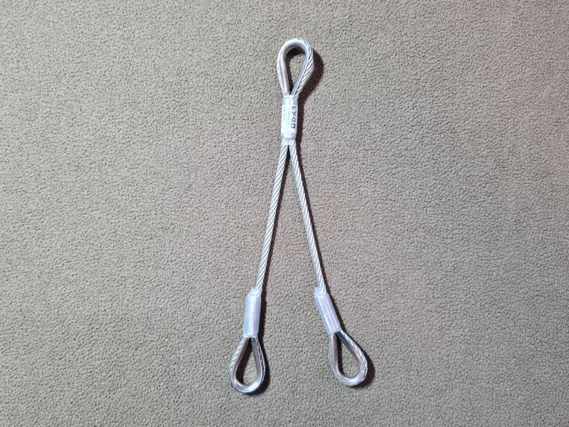

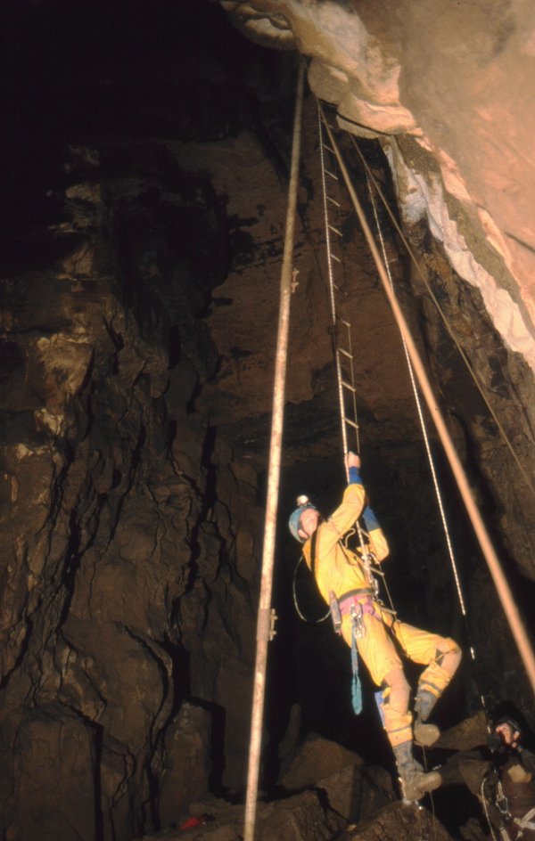
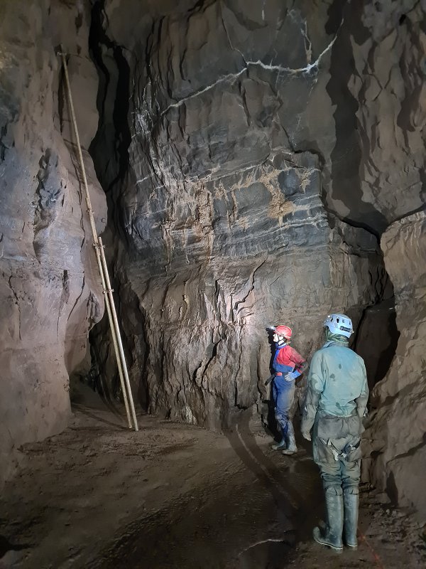
An older tool used to ascend an aven which cannot be free climbed. Usually constructed from a series of short scaffolding bars (often aluminium) that are clamped together to make a longer semi-sturdy pole. A ladder is then hung off the end, and the pole is raised up into the aven. A lightweight caver then climbs the ladder to reach the top of the pole. The pole is quite flexible, depending on its length and the number of pieces that have been joined, so a significant amount of height and positioning can be lost due to it bending. The parts of a maypole are often very heavy and cumbersome, and therefore this approach is limited to caves with convenient passageways where they can be carried.
The earliest equivalent to maypoles were simply rigid siege ladders, that were used to climb over castle walls. Very complete maypoles were then for that purpose, with all the features that would later be reinvented by cavers. Egyptians were using rigid ladders very similar to a modern wooden ladder, to scale Canaanite city walls during sieges from at least 2400 BCE. One was depicted in the tomb of Kaiemheset, which had wheels to help move it. The general idea appeared in numerous European military manuscripts during the Middle Ages, often with wheels, or built into crane structures. A manuscript from France in 1275-1375 referred to as the British Library's Royal Collection 10 E IV, Decretals of Gregory IX, depicted siege ladders with hooks on the top, which could hook onto the top of a castle wall. Bellifortis, a military manuscript written by Konrad Kyeser between 1402 and 1405 in the Holy Roman Empire, now Germany, also depicted numerous siege ladders with hooks on the top. Some editions also included ropes being used to stabilise the ladder. A maypole was then depicted with a rope ladder and a rope that could pull the ladder up and then stabilise the pole, in De Re militari by Roberto Valturio, published in 1472 in Rimini, now Italy. The pole appears to be segmented, with sections that fitted inside each other to make the pole as long as needed, which would make it as functionally complete as the maypoles used by cavers. The pole also held on to the top of the wall using a hook that was shaped like a hand. The ladder was also segmented, so that it could be joined into longer lengths. Leonardo Da Vinci, who had a copy of Roberto Valturio's book, depicted a very similar maypole and rope ladder (click "Verso") in 1486, in Codex Atlanticus in the Holy Roman Empire, now Italy. It was not segmented, and did not have ropes to help stabilise it, and instead needed the top of the maypole to hook over the top of a wall. Another drawing showed an extendable pole made in two separate lengths, where a rope could be pulled extend it. French inventor Nicolas Grollier de Servière developed a segmented pole that turned into the rungs of a rope ladder after being hooked over a wall. The date of its invention is not recorded, but was probably during his retirement, which began in 1642 and ended with his death in 1689. Details were published in 1719.
Rigid poles had long been used to access high level cave passages, and had been historically used for collecting birds' nests (as early as the year 800 in southeast Asia). French caver Norbert Casteret used a long pole constructed underground from pipe segments that could be screwed together, during the exploration of Grotte Cigalère in 1932 (or 1933 - Norbert Casteret's book appears to have a mistake in the time scales). Unlike a more common maypole, it did not have a ladder or rope attached to it, and the pole itself was climbed instead. By 1933, however, a ladder had been added, which was clipped to the top of the pole. French cavers Pierre Chevalier and Henri Brenot devised a maypole some time after 1935 (described in Pierre Chevalier's 1951 book Subterranean Climbers), but it was not until 1940 that French caver Fernand Petzl actually created a segmented maypole, which could be assembled in a cave by slotting the parts together, which was used to explore the Dent de Crolles system near Grenoble. It used a ladder connected to the top. Their caving companion Charles Petit-Didier helped improve the design in 1942 so it could be used in longer lengths, using guy ropes. Irish cavers J.C. Coleman and N.J. Dunnington attempted to make a segmented scaling ladder in 1943, but it collapsed during its first use underground in Pollnagollum. In 1944, French caver Henry P. Guérin described the Fernand Petzl and Charles Petit-Didier maypoles, as well as another maypole that had ladder rungs built into it called a parrot mast, and one that used a pulley and a pull-up cord to raise a ladder. Charles Petit-Didier made a lighter weight maypole with segments that screwed together, in 1946. Also in 1946, British cavers Ralph D. Stride and Arthur H. Stride stated in the British University Of Bristol Spelæological Society newsletter that "an iron ladder or pole" would be needed to ascend a waterfall in Longwood Hole, but it appears that nobody actually did so during the exploration, which also involved the Wessex Cave Club. The passage at the top is not described or shown on the survey, and it was not found until 1980. There was no suggestion of using a rope ladder attached to the pole, and the pole would need to have been manually climbed. J.C. Coleman and N.J. Dunnington then independently invented a segmented maypole with a rope ladder, and used it successfully in 1948. British caver Peter Harvey, a member of both the South Wales caving Club and the Wessex Cave Club, created a maypole to access high level passages in Ogof Ffynnon Ddu and Dan yr Ogof in 1948, and this is where they first earned the name maypole. He stated that the ladder was better than the pole climbing method originally used by Norbert Casteret, and that it used ropes held out to the sides for stabilisation. His design was made from 2.4 metre lengths of aluminium alloy scaffolding bar, which could be joined using standard scaffolding joints. It had been tested underground to a length of 4.8 metres, and on the surface to a length of 7.6 metres, but would need a more significant scaffolding construction to ascend higher heights. British caver George Cornes used a similar device in 1952 in Easegill Caverns. While the various French cavers all knew of each other's work, it is not known how much the cavers from other countries knew about the inventions of the others.
This history section only covers maypoles. This article also has a detailed history of many of the other devices and techniques that are used for vertical caving.
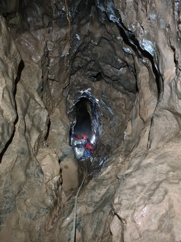
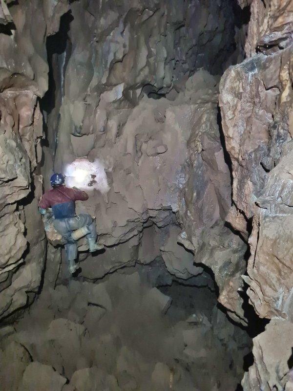
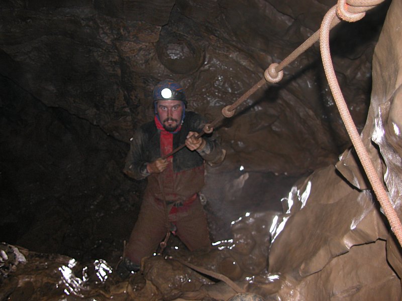
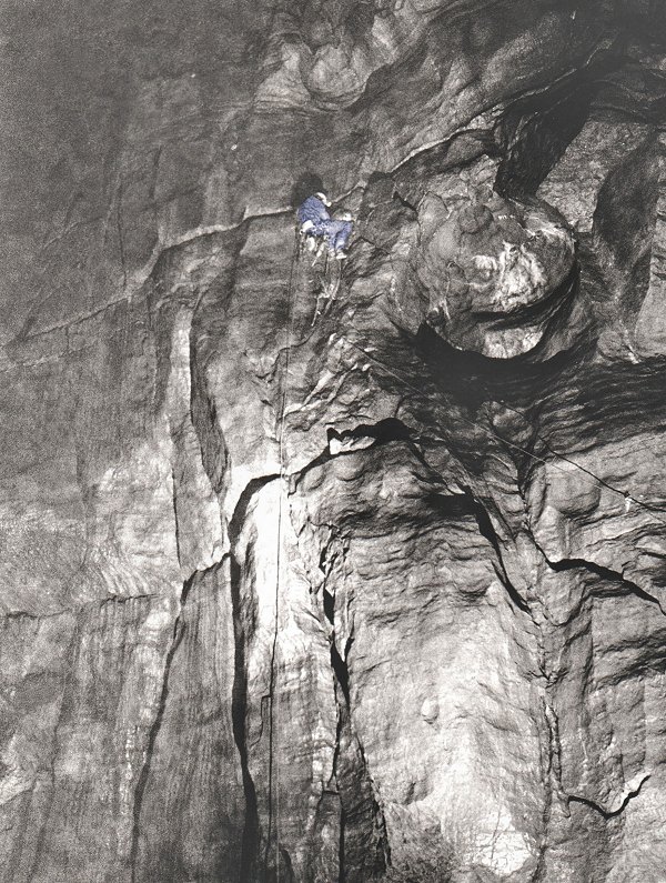
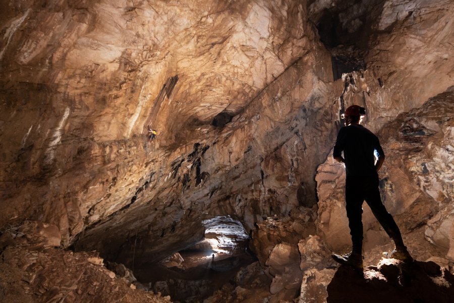
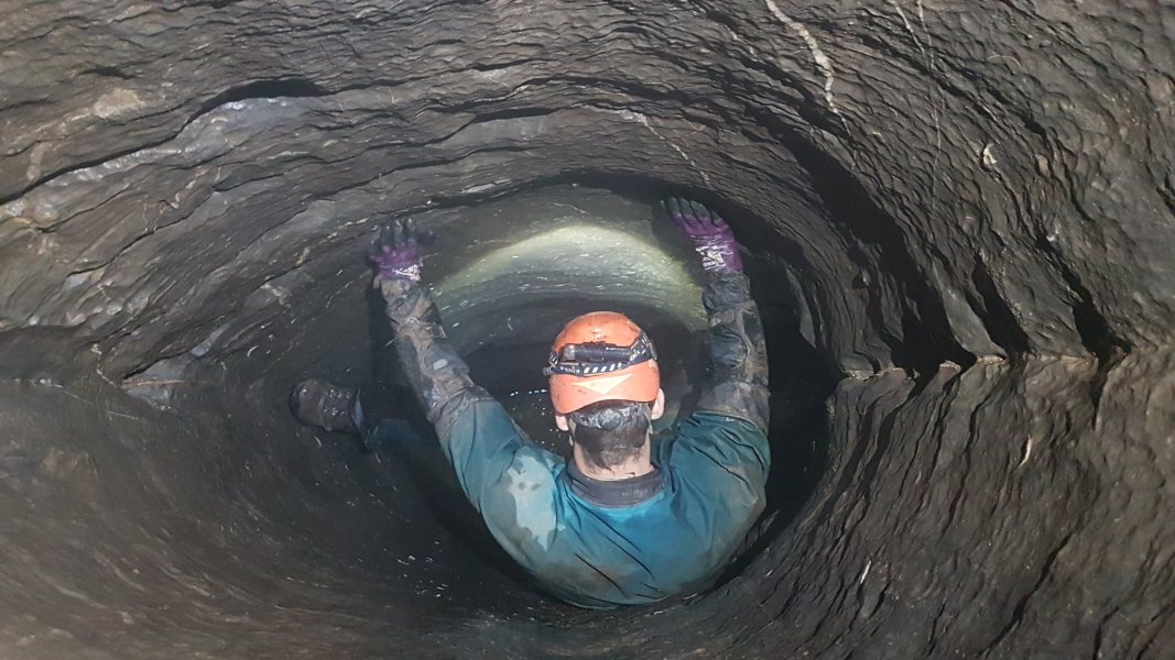

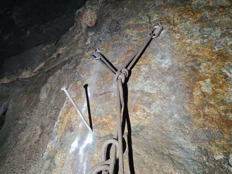
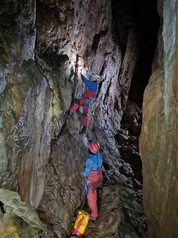
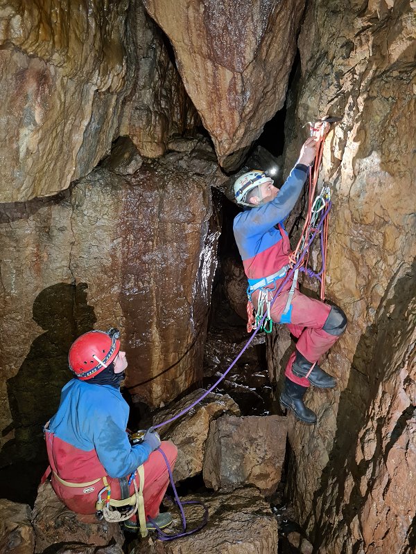
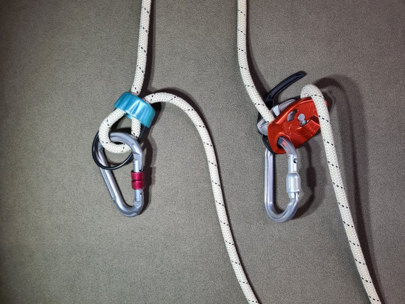
A device used by belayers to pull a lifeline through as a climber climbs, and to stop it from moving when a climber falls. An Italian hitch is far more common with caving, while dedicated belay devices are commonly used by climbers. The most simple dedicated belay devices are manual friction device, such as a basic belay plate or Sticht plate, or "ATC" devices. Dedicated belay devices can be auto-locking or self-locking, officially called an "assisted braking devices" (ABD), meaning that they do not allow the rope to pay out quickly in the event of a fall, unless the belayer explicitly allows it. Instead, they use some mechanism such as trapping the rope or adding resistance, if the rope moves in the wrong direction without a handle being held, or if the rope moves too fast. Most of these do not function well when mud gets into the moving parts. Semi-assisted braking devices function like a belay plate with no moving parts, but shift into a position where there is more friction if the rope rapidly pulls through them. These can be more reliable than assisted braking devices, when used in muddy places like caves. (Many designs, many brands, many names.)
In general, the minimum breaking strength of a belay device is largely meaningless, since many designs will not be able to grip a rope with enough force to break the device, because they are designed to allow the rope to slip through them at high loads, in order to absorb the shock load. As a result, they might only specify a working load limit. Some will only specify they can cope with a certain fall factor with a nominal load, such as 80 kg, which is required for their PPE rating.
In 1851, fire brigades in Ulm, German Confederation (now Germany) were using a ring attached to their belt as a descender, by wrapping the rope through it twice. By 1877, fire brigades in Austria, Austro-Hungarian Empire, were wrapping the rope through a carabiner several times, known as a carabiner wrap, to lower someone. The first known dedicated device was a carabiner with an integrated pulley and braking lever designed in 1882 by the German Lohner brothers, made for the fire brigades. It would automatically add friction when released, and reduce friction when a lever was pulled, just like a modern Petzl GriGri, and could be used for lowering people. The inventors complained about the pulleys falling off existing designs (which were not integrated within a carabiner), which seemed to also have a similar lever. No existing devices were described in a comprehensive manual from that region 5 years earlier, so the exact details of those earlier devices are not known. In 1897, Austrian inventor Zdzislaw Szpor created a dedicated belay device for self belaying, for use with rope access, in the Austro-Hungarian Empire, now Poland. The device was incredibly complex, and almost certainly had been through many years of development beforehand (it was definitely created in 1896 or earlier), though no previous versions were found. It could safely catch a fall, could be adjusted for different sized ropes, and could be used as a descender after catching a fall. Although it was clearly designed as a belay device, it was registered in the USA as a fire escape descender, and probably also Canada, so is likely to have been widely available.
In 1904, a lever cam device was patented by Austrian locksmith Michael Gayer, which he called a "clamping sleeve for climbing devices". This was sold as a "climbing device" by F. Turczynski Jagd- und Touristen-Asrüstingen, a mountaineering shop in Vienna, Austria, the city where Austrian mountaineer Karl Prusik lived, run by a member of the Wiener Alpenklub (Vienna Alpine Club), which Karl Prusik was also a member of. The design had a very limited range of rope sizes which it could work with, and used a fiddly bolt and wing nut to close a hinged section around the rope, which would have been very easy to drop by mistake. It was advertised only as a fall arrester in Austrian mountaineer E. Fink's Touristen-Vademekum publication in 1904, for self belaying when climbing up or down, for climbers, quarry workers, miners, construction workers, roofers and plumbers. By July 1910, German climber/mountaineer Hans Dülfer was using carabiners as a belay device, presumably using a carabiner wrap. Body belays remained the main approach in the climbing world. In 1910, Anwendung des Seiles, published by the Bavarian section of the German Alpine Club, suggested the use of an emergency knot when climbing or abseiling on a doubled rope. One strand of the rope would be fed through the climber's belt, and the two strands of the rope would be tied together 1 metre above the ground. If they lost their grip, they would fall until their belt slammed into the knot. This would probably fail, since the stretch would allow them to hit the ground anyway, the weak ropes of the time would probably snap from the impact, the climber would probably be severely injured from the abrupt stop, and even if nothing went wrong, they had to stop 2 metres from the ground, and with no hands available, untie the knot so that they could complete their descent. It was a terrible, terrible suggestion, but somehow was still being suggested in the 1942 edition. Throughout this time, that booklet also contained instructions on how to use body belays, both for top roping and bottom roping (both of which were first mentioned in the 1910 edition, with bottom roping being primarily used for traverses). German mountaineer H. Sixt proposed a lever cam device, which German mountaineer Franz Kröner then improved and manufactured in 1911, called a "climbing lock". It was intended to be used as a self belaying device while abseiling, but could have been better used as an ascender.
In 1920, carabiners were clearly described as being used for belaying using a carabiner wrap, in a German and Austrian climbing newsletter article by Hermann Amanshauser (later a Nazi SS officer). The article described how traditional belaying was too primitive, and that recently developed techniques made climbing dramatically safer. He described the modern approach to bottom roping with the rope running through multiple carabiners attached to anchors during the climb, and appeared to describe the use of half ropes, by saying that ropes can be used in pairs for big or difficult climbs. In 1922, Anwendung des Seiles showed that belaying was becoming more demanding, with bottom roping being used for lead climbing falls very slightly above the highest anchor. The use of half ropes had started, allowing one to be kept tight while the other was kept loose while being placed higher, but even so, the same body belay approaches were still being used. The publication mentions that it is hard to catch falls from above the anchors, and this should therefore be avoided. Karl Prusik claimed in 1931 that the "climbing locks" could not be used when the ropes swelled because they got wet, and while he did not clarify which devices he was referring to, it was probably the devices made by Michael Gayer and H. Sixt. In 1942, Anwendung des Seiles showed how a Prusik knot could be used between the descender and hand on the down rope, for self belaying while abseiling. This approach still remains in use today. The figure of 8 was invented in 1943 by Austrian doctor Max Pfrimmer, but its value as a belay device was not realised at the time.
In 1944, French caver Henry P. Guérin suggested using a cows tail which was clipped to the rungs of a ladder as a method of self belaying, though this does not actually satisfy the safety requirements, and can damage the ladder. The Cave Research Group from Britain published some early devices. The Slipgrip, a crazy-looking canister which hides the fact that the real magic is simply a helical friction hitch, was created by British caver W. H. Little in 1955 for self belaying. Another self belaying device from 1955 functioned the same way as an Alpine clutch, though it involved a box with moving parts. It was created by British caver W. E. Clarke. In 1962, British caver Derek Ford wrote in the Wessex Cave Club journal that a Prusik knot could be used for self-belaying when using a ladder, even though it would have to be manually moved up the lifeline. This is exactly the same idea as the Slipgrip, just using a different knot. French caver Paul Courbon used an ascender made by French caver Bruno Dressler as a self belaying device, which was used to descend the Puits Lépineux shaft of the Gouffre de la Pierre-Saint-Martin, in France/Spain, using ladders in 1965. Swiss mountaineer Franz Ruso is said to have first proposed the use of the Italian hitch with a carabiner as a belay device in 1967. The French approach of using an ascender for self belaying while using ladders was described in Britain in the Westminster Speleological Group Bulletin Jan/Feb 1969, referred to as a brake-blocker. This was further described and widely advertised in Descent 10 in 1970, as a useful feature of the relatively new Petzl Basic ascender, clipping into the hole at the top of the ascender so that it moves more easily. It was described as being very useful when ascending, but fiddly when descending, requiring the same action as reverse prusiking to disengage it. Because it relied on someone bottom weighting the rope while ascending, the last person needed to be belayed more normally from the pitch head, using a pulley and ascender for capturing progress, as with hauling.
Belay plates were the most basic belay device, invented in 1969 in Germany by Fritz Sticht, and first sold by German company Salewa. The figure of 8 was recognised as a potential belay device some time during the 1970s (something it is no longer recommended for, as it can break the gate of a carabiner if it is shock loaded after not being loaded). Petzl released the Shunt in 1972 as a self belaying device to use while abseling. Although it has a slightly different lever arrangement, it is used in exactly the same way as the previous climbing locks. In 1972, British caver Guy Talbot and Cambridge University Caving Club researchers developed and tested a fall arrester which used the exact same fixed bobbin and rotating cam arrangement as the Stop but failed to get the idea working. The intention was for it to be used as a descender, like a Stop, after catching a fall. They also tested a tubular device which relied on kinking the rope when catching a fall, and could then also be used as a descender. It could optionally have a lever cam fitted into it to make it grip more when initially catching the fall, which could be disengaged by tilting the device. Finally, they also tested a more basic lever cam device, which could not be used as a descender. The basic idea behind rocker fall arresters was developed in 1975 by Russian mountaineer Виктор Алексеевич Козлов (Victor Alekseevich Kozlov), called Капелька ("Kapelka", meaning droplet). It was originally used as an ascender. After the Italian hitch started to be used for belaying in the 1970s, the HMS carabiner was introduced in the 1980s. Tubular belay devices first appeared in 1983 with the Latok Tuber, designed by Jeff Lowe and sold by Latok Mountain Gear. The auto-belay, a device often installed at climbing walls that belays climbers and gently lowers them to the floor after a fall or at the end of a climb, was developed by German inventor Markus Lehner in 1989. Several more designes, using different approaches to provide a slow descent, appeared during the 1990s.
Through the previous decades, many people patented lever cam devices as fall arresters for self belaying, but these all operate on the same principle which had been used at the start of the century, and most did not deserve a patent. In 1989, Canadians John Stephenson and Ian McGuffe patented a device that used a tooth wheel which allowed it to move up and down the rope freely as long as it did so slowly, but which used a governor inside the wheel to lock the wheel when the rope moved too fast during a fall, causing the wheel to lock up. The wheel then acts as the face of an eccentric cam ascender, and moves upwards to jam the rope, catching the fall. This is now sold as the Petzl ASAP, but that only appeared on the market in 2004, 5 years after the patent expired. The first auto-locking GriGri, extremely similar to the Lohner brothers' design, was developed between 1989 and 1991 by Petzl, as an adaptation of the Stop. The 2011 version added panic detection so that pulling the handle too far would cause it to lock off again. Tubular belay devices earned the name ATC after American company Black Diamond released their Air Traffic Controller in 1993, a reference to how the belayer controls the climber. In 1995, Italian company Sistemi Di Sicurezza Europa patented a fall arrester in several countries. This appears to have introduced the rocker lever from the Капелька to fall arresting, an approach which is now used by almost all guided-type fall arresters, since the patent expired in almost all countries after 10-20 years. This original patent shows that it also used a spring loaded lever to improve the catch time, which is lifted away when it is hanging from the carabiner, just like the Camp Goblin and Climbing Technology/Skylotec Easy Speed/Move, both made in Italy shortly before the European patent expired. Unlike either device, the patent shows an optional lever which could be used to progressively release the rope, so that it could be used as a descender after catching a fall. The first semi-assisted braking device was Swiss company Mammut's Smart, which appeared in 2009. Edelrid patented the idea behind the Fuse in 2020, which is a combination of John Stephenson's and Ian McGuffe's approach, but instead of the wheel gripping the rope directly, it pushes an eccentric cam against the rope so that it can work like a common ascender.
This history section only covers belay devices. This article also has a detailed history of many of the other devices and techniques that are used for vertical caving.
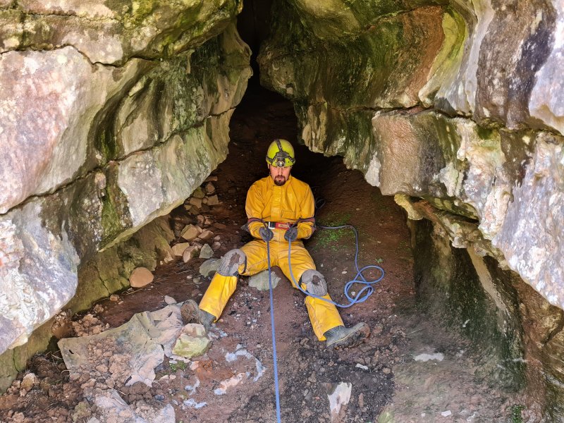
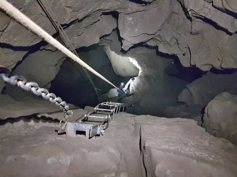
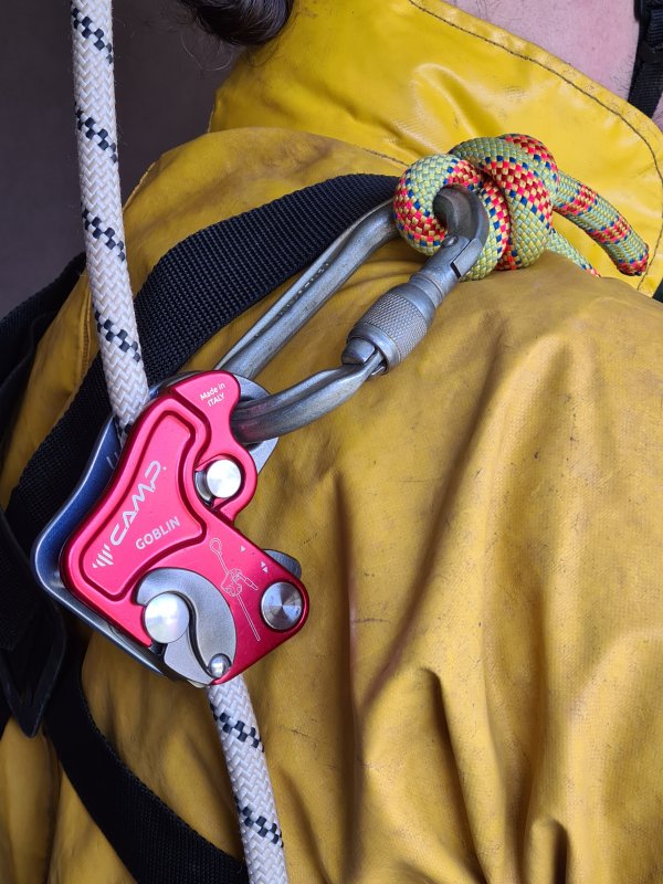
Various methods to use a lifeline without needing a belayer. Typically, this might mean setting up the lifeline so that it is connected above a ladder or climb, and then connecting to it with an ascender. This may be done while solo caving, but even when caving as part of a team, it might occasionally be done with a rope climb, where the handline can also be used as a lifeline while climbing.
For solo caving, it is important to consider whether it would be possible to reach the ladder or rock face after a fall has been caught, since a fall could result in hanging from the lifeline without being able to reach anything in order to get back off the lifeline. Without SRT gear, this could result in the need for rescue, and waiting for the rescue while hanging from the lifeline would probably result in suspension syncope.
Toothed cam ascenders can damage the rope when catching a fall, so lever cam ascenders are preferred, even though many climbers use toothed cam ascenders for this purpose (many claim that since they have never had an issue, it must be safe, but trustworthy testing has shown that issues can and do happen). Progress capture pulleys are sometimes used by climbers, but these are almost never suitable for this purpose, as they typically rely on toothed cams, with even more risk of damage to a rope than toothed cam ascenders. The most common progress capture pulleys used for this, the Petzl Traxion series, are specifically not rated for this purpose by the manufacturer, even though many climbers try to claim otherwise (they are actually rated as an ascender). Because so many climbers make this mistake, Petzl published an article stating that climbers should not rely on a Traxion device, since it is not designed or intended for that purpose, and they need to have another device that can provide proper protection as well. Unfortunately, many climbers misunderstand that article, and assume that Petzl have said that it is good for this purpose as long as it is combined with another inappropriate device, but that is not the case. Petzl have never rated the Traxion devices for catching falls, and have never stated that any of them are suitable for the purpose, no matter how many other devices are used. Because many climbers continue to publish dangerous advice telling each other to copy them, many other manufacturers explicitly state that their progress capture pulleys are not designed to be used for this purpose, sometimes even producing their own videos to show how dangerous the advice is. This dangerous advice is frequently spread by climbers on YouTube, but no matter how knowledgeable they may seem, it is bad advice, even if they have published books about the subject. If a climber ever suggests using a progress capture pulley that is not specifically rated for catching falls by the manufacturer, all of their advice regarding the subject should be treated as dangerous.
It is unusual for cavers to do the kind of solo caving that needs self belaying, but self belaying on a rope climb is more common. In cases where it is used, cavers are also likely to use a toothed cam ascender simply because that is what they already have on their SRT gear. However, it is worth noting that while it normally copes with a bit more, even at surprisingly low fall factors such as 0.06 (2 kN with an 80 kg load) on a static rope, a toothed cam ascender can completely sever the rope's sheath, leaving just the cores. That could be just a 30 cm fall on a 5 metre rope. This rises dramatically with increasing load, and by fall factor 0.3 on a static rope, severing the sheath is extremely likely no matter what weight the climber is. This can happen much more easily on ropes with a thinner sheath, so it happens far more easily on a thinner rope. By fall factor 1, it is almost guaranteed, even on a dynamic rope. The risk is exponentially higher as the top of the rope is reached, as the fall factor is exponentially higher for even a short fall. Toothed cam devices are not meant to be used for self belaying, they are designed for static loads.
The most common lever cam device for self belaying is a shunt, even though the official Petzl Shunt is not classified as PPE. It is important to note that due to the way a fall can pull the Shunt in an unexpected manner, it can end up oriented in a way that causes the lever cam not to engage at all, or to release the rope completely, so that it will not succeed in catching the fall. Shunts should not be used for self belaying. Various Gibbs ascenders can serve the same purpose, as they can take nearly twice the shock load of a toothed cam device before they damage a rope, but the manufacturer recommends against it anyway. The Petzl Rescucender is an ascender which is almost identical to a Gibbs in the way that it works, but is much easier to open, and gives very similar results in testing, so it is a very useful alternative. However, it does not work very well when descending, because it has a spring forcing it to grip the rope, so it does not move downwards reliably, unless it is pushed downwards. It is also not officially rated for catching falls.
Dedicated fall arresters are made for rope access, and although most of these are designed to be used with the thicker ropes used for rope access backup lines, there are some that can be used with the thinner ropes normally used for caving. These devices are designed to minimise the damage to the rope when catching falls, and are specifically made for this purpose, so they are the right type of device to use.
Some cavers, and far too many climbers, may choose to use a dedicated auto-locking belay device, which may seem like the correct thing to use, but auto-locking belay devices are supposed to assist a belayer, not replace them completely, and it is quite possible for an auto-locking belay device to fail to catch a fall if there is no hand to hold the down rope. Many will also fail to catch the fall if something presses on parts of the device during the fall, which is easily possible. Using an auto-locking belay device means having to randomly stop to pull the rope through the device, as it will not normally feed through automatically. Until it has been pulled through, a fall will result in a much longer drop before it can catch the fall. It is also worth noting that the most common dedicated auto-locking belay devices will start slipping down the rope and fail to function at a lower force than where a Gibbs device or Petzl Rescucender would damage the rope.
Climbers typically recommend having at least two self belaying devices in use at the same time, in case one of them gets caught at an odd angle during a fall, and fails to grab the rope. Ideally, they should be two totally different designs, so that whatever caused the first one to fail is unlikely to affect the second one in the same way. In addition, they should each have their own rope, so that if one rope gets damaged by a failure in one of the devices, the other device still has a functional rope to use. These should be configured so that one of the devices normally does not engage unless the other device fails (such as by having it on a much longer tether), since if both catch at the same time, the shock load experienced by the user is doubled (because twice the thickness of rope is performing the catch). However, dedicated rope access fall arresters often expect to be the only device used to catch a fall, and they are tested and certified to ensure that they are trustworthy enough for that.
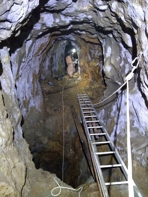
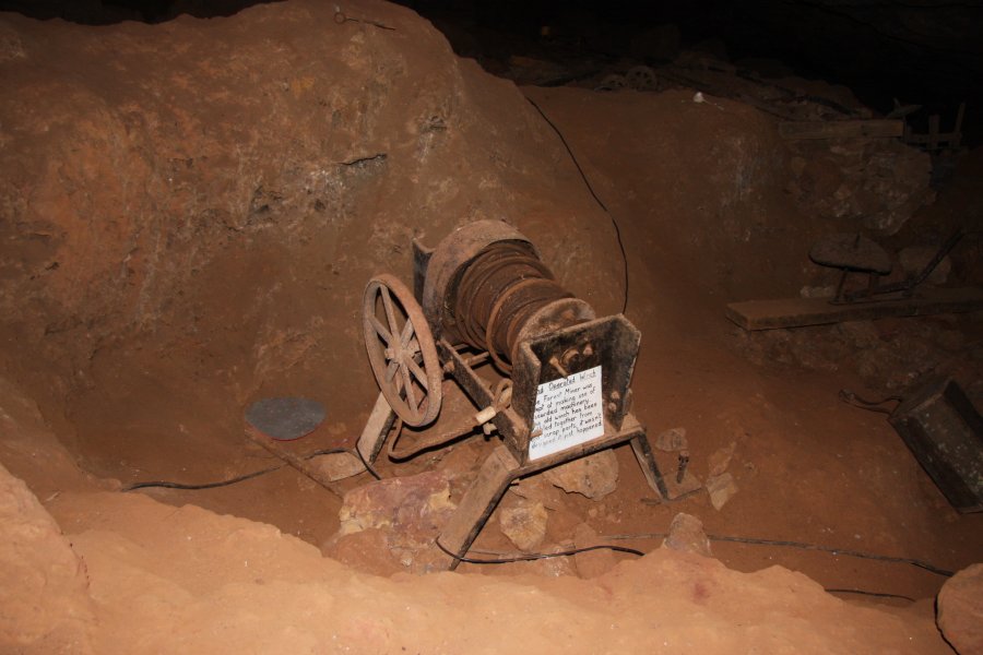
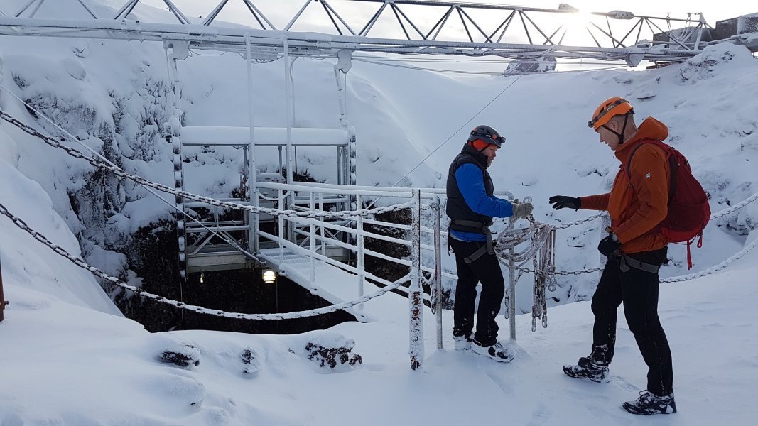
A mechanical device used to pull or slowly release a rope or cable, which has been almost completely replaced by SRT, and is very rarely seen. This can be used for lowering someone or something down a pitch using a rope, or hauling them back up again. This is different from a descender or ascender because a winch remains static on the pitch, while the caver or other object moves up or down the pitch. When using a winch, the rope moves at the same time as the caver, instead of remaining in position like it would with SRT. Typically the winch would be positioned at the pitch head, but it could be located at the pitch base if the rope runs through a pulley at the pitch head instead. Alternatively, in extremely rare cases, a winch might be connected to the caver and move with the caver, while the up rope remains static on the upper part of the pitch, but there is no down rope below the caver, since the down rope is wrapped around the winch. A winch may use manual power or machine power. Portable types are generally a historical item that no longer exists in vertical caving, but for a long time, raising or lowering cavers using this approach was the most common way to navigate significant pitches. A large team is normally needed to use manual power, and cavers might need to be left behind at each pitch head, to haul up returning cavers.
Motorised winches are largely used only with surface shafts. They may use an internal combustion engine (petrol/diesel) or be electrically powered. Electrically powered winches need an external generator, powered by an internal combustion engine. Either way, an internal combustion engine would be needed, so these are not really welcome inside caves. Their use is now confined almost exclusively to rescue situations, particularly those involving non-caving rescue organisations, such as the search and rescue helicopters, urban search and rescue, or the fire service. They might also be seen in use with showcaves, and active mines. In very rare cases, they might be used with outdoor adventure groups, but this would not be considered to be normal caving (or even relevant to caving), and is really just a way to get tourists with no caving skills into places they could not get to with their own abilities. Small scale devices might sometimes be used for cave digging operations.
Winches bring significant issues. Most obvious is the weight and bulk of the winch, which needs to be transported to and through a cave. When there are multiple pitches, the winch needs to be lowered down one pitch, and used on the next one, then raised up each pitch in turn to be used on the one above. If heavy enough, another winch might be needed in order to raise the winch, or a person would need to ride the winch up a pitch, cranking the handles as they go! The winch rope might snag rocks and boulders, dropping them on the person who is connected to the winch. The winch rope might get stuck in cracks, or damaged where it rubs against something sharp. The winch might pull the person against obstructions, injuring them before the winch controller has a chance to stop the winch. Mechanical faults can disable the winch, and they need to have a failsafe design so that motion is safely halted in the event of a mechanical failure, though this can leave a person hanging on a winch cable for as long as it takes to repair the winch. The person connected to the winch is totally at the mercy of the person controlling the winch, which means that some effective means of communication is needed, such as a telephone. Winches are incredibly risky, prone to failures, and overly awkward.
The terms originate in sailing and mining, and have very specific differences, but within caving, the term winch is generally used for all of them. However, if you care about the distinction, a winch wraps the rope around a spool and keeps it there, so the coil gets bigger as more rope is wrapped around it. A windlass (mining device with a horizontal spool), capstan (sailing device with a vertical spool) or whim (large mining device with a vertical spool) temporarily wraps the rope around a spool for grip, but then the end of the rope feeds back out of the device, and needs to be managed some other way. A particularly large whim or capstan may be horse powered, with horses walking in circles to turn it. A hoist is any kind of spooled device that is designed specifically for lifting and lowering (meaning that it is actually the most appropriate term for what cavers call a winch), while a winch is intended for pulling loads horizontally. A gin or engine might be used historically to suggest that an artificial source of power is used, such as a steam engine or water powered engine. However, the term was used for manually powered winches in the era before steam engines.
Winches may have first been used in Assyria around 700-600 BCE. Greek historian Herodotus (from what is now Turkey) wrote about their use in the Persian Wars to create a brige at Hellespont (the Dardanelles), now Turkey, in 480 BCE. Although mechane (μηχανή) cranes for lifting people were used in ancient Greece at around the same time, it is not known if these used a winch mechanism, counterweights or a more simple lever system. Winches were used in Ancient Greece, the Roman Empire, and throughout Europe during the Middle Ages, sometimes as part of a very large crane. From Roman times, these may have a human sized tread wheel (hamster wheel), which people could walk in to generate the winching force. The rest of this section concentrates on the use of winches in caving. Miners will have had access to winches, so there is a chance that miners throughout those centuries were using winches to explore caves that they encountered while mining. However, they did not often keep records of what caves they visited, or whether they descended them using winches. Winches became so common in mining for lifting rocks that it did not seem necessary to say that they would be used for people. Most of the developments happened in mining and sailing, so these developments are not covered. Unfortunately, most records neglect to say whether a winch was used when lowering cavers down a pitch, so this section only covers cases where winches are suspected to have been used.
Motorised winches rely on several other inventions. British scientist Michael Faraday invented the first electric generator in 1831, which needed a mechanical power source to turn it. In 1839, the development of a portable steam engine, followed by the development of a viable traction engine in 1860, might have made it possible to bring a mobile steam powered winch to a surface shaft, and these were used in mining (a portable steam engine was used at Cystanog Lead Mine, near Carmathen in southwest Wales in 1853), but I have not found any record of them ever being used for caving. The first functioning petrol engine was created in 1876 by German engineer Nicolaus Otto. The electric winch was invented in 1885 by the British Edison-Swan company, but they only became small enough to use in the 1950s, at about 130 kg for a small model. In the 1890s, small hit-and-miss petrol engines were developed, which were used for various winching purposes, but there are no known records of them being used for caving. Diesel engines were invented by German/French inventor Rudolf Diesel in 1897. Diesel generators appeared very soon afterwards, and by World War II, some models weighed as little as 120 kg. In 1928, diesel winches became available, but it seems that cavers made their own instead. Electric generators small enough to be carried by hand were first created by Japanese company Honda in 1965.
The Covolo di Butistone cave (known as Kofel in German) in the Brente river valley in Italy has been described since 1004 CE as being used as a fortress, situated part way up a tall cliff. Over the centuries, it has been modified heavily to add buildings and tunnels that were carved out of the rock, and to remove the holds that were originally used to access it by climbing. Most of the work is thought to have been done for the Scaligeri princes of Verona in 1321-1337, though it had changed hands several times after then (and a few times before), and any other group involved could have made changes. It is known to have had its fortifications improved in 1509, under the Holy Roman Empire. For a long time, a hand powered winch was the only way to access the fortress, which had probably been installed between 1321-1337, since the space for it was provided by the early layout. If so, it will have been the earliest known winch used to access a cave (though it is possible that one was used at the nearby Covolo di Pisciavacca cave fortress at some point during 1000-1509). It will have been powerful enough to lift cannons into the cave, and could lift two people at once when needed. The winch was mentioned by Domenico Odorico Capra in a 1580 report to the Republic of Venice, as an "argano" (an Italian word meaning any kind of winch), located in the cave above. It was described in 1596 by a saboteur (who had not seen it) as a "mangalo", which at the time was the Italian word for a wooden ballistic catapult (called a mangonel in English), that used a horizontal winch spindle to tension it, powered by vertical handles that were turned by hand, and were either permanent (like a ship's wheel), or may be removable levers. It was described again in 1598 by a visiting clergyman (who had seen it) using the same word. It was described in the same year in a report by Venetian superintendant Francesco Caldogno, as using the "force of a wheel that those of the fortress turn", which was a part of the fortress made by "men in ancient times", suggesting that the winch was old enough by then for its origin to have aready been forgotten.
The winch itself is not shown, but its use for hauling people on a boatswain's chair was depicted in around 1610 (often mis-stated as early sixteenth century) in a painting, and in an enormous map (bottom-right corner) of the Tyrolean Alps in 1611, both by Matthias Burgklechner (or spelled Mathias and Burgklehner). His visit may have been years earlier. It was described in 1640-1682 by Mario Sale in Storia manoscritta di Bassano as "a rope pulled by a manganello". In 1650, "manganello" in Italian referred either to a catapult, or to a screw press for clothing where you have to walk around in circles pushing a lever to tighten the press (it now means truncheon), which might refer to a capstan-style winch that was used at the cave. The same word was used again in 1692 in "Processo in materia de Confini" (Biblioteca civica Bertoliana, b651 / Ex calto 2, number 15). In 1678, it was described by Kryštof Harant z Polžic a Bezdružic of Bohemia (now Czech Republic) as using a "roller beam", suggesting that the rope was wound around a large wooden beam. The fortress continued to be accessed this way until 1797, and was mentioned by many travel writers. By the 1800s, it could only be accessed using very long ladders instead. In 1820, the winch was described as having a rachet made from a toothed wheel with a sprung piece of iron pushed into the teeth, so that it could only rotate in one direction, and would hold its position if it was not being pushed around. It was manually turned by the people in the cave.
In 1595, François de Chalvet from France reported that the locals were using "very dangerous machines" to descend 103 metres into the Gouffre de Padirac, to mine guano to make saltpeter. These would have been winches, thought to have had a boatswain's chair consisting of a wooden cross bar tied to a rope. In 1659, Edward Leigh wrote about the first known use of winches to descend a pothole for what is likely to have been cave exploration purposes, which took place "about 60 years" earlier (aproximately 1599). British local George Bradley was lowered into Eldon Hole on a rope using "engines" (presumably a hand powered winch, since neither steam engines nor horse powered whims existed in the area at the time), on the instructions of politician Henry Cavendish. The distance he was supposedly lowered on rope, 73 metres, would have easily been enough to reach the current bottom, where he then claimed to have found many animal bones, and possibly human bones. However, there are contradictory stories claiming that he was lowered further, or that he lowered the end of the rope much further to reach the bottom, and while these are significantly exaggerated, it is possible that there was a further shaft that is now buried below the rubble dropped in by tourists testing the depth of the hole (which is extremely significant).
In 1748, a winch was used to descend Propast Macocha (Macocha Abyss) in the Czech Republic by two miners instructed by Austrian Joseph Anton Nagel. This was repeated in 1776 by Czech prince Karel Josef Salm, a 1784 expedition led by Czech explorer Karel Jan Rudzinský, 1808 by Austrian caver Hugo František Salm, 1856 by Czech paleontologist Jindřich "Heinrich" Wankel, 1864 by Czech archaeologist and explorer Martin Kríž, Czech citizens Martin Kala and Josef Nejezchleb at some point to retrieve bodies from suicides, 1889 by Austrian historian Othmar Skala, 1894 by Czech tourism developer Adolf Podroužek, 1898 by Czech geologist Florian Koudelka, and 1901, 1903, 1905, 1907 and 1909 by Czech caver Karel Absolon, who then used an iron ladder from 1913 onwards.
In 1761, Alexander Catcott wrote that two miners had been lowered 64 metres to the bottom of Eldon Hole, thought to have been in 1760, using a mining winch. In 1771 British geologist John Lloyd was lowered 57 metres into Eldon Hole by "8 men" using a rope and winch, but stated that at least two or possibly three miners had already visited the bottom. A great deal of caves were descended by Slovenian miners in the 1700s, typically using winches. This included Jama Za Krasco No. 4, which held the world depth record of 247 metres depth from around 1780. It was already being worked since at least 1778, using winches for 13 pitches, and was visited by Slovenian mine inspector Anton Žerovnik in 1780 (at which time the mining had already ceased) and Swiss geographer Lois-Albert Necker de Saussure some time before 1841, presumably using the winches. A British team consisting of John Birkbeck, William Metcalfe, William Howson and 7 others used a winch with a large bucket to sit in for their successful second attempt to descend directly down Alum Pot in 1848. During the late 1840s, miners were using a winch to explore Moaning Caverns in California, USA, and American cavers started to use winches around that time too. In 1851, Colombian priest Romualdo Cuervo was winched 115 metres down into Hoyo del Aire, in a basket held by the winch cable. In 1867, Count Murat and Mr. de Salvagnac were lowered in a large bucket or wicker basket into the Gouffre de Padirac, to retrieve the body of a murdered girl, presumably using a winch.
In 1880, the British Lamb Leer Cavern was rediscovered by miners Andrew Lyons and two others, and a winch was installed, presumably that year but not for the first visits, so that foreman Joseph Nicholls, Andrew Lyons and other miners could access the Great Chamber. In 1882, Walson Richards (a newspaper corespondent and the only non-miner), S. F. Sopwith, Thomas Wynne, James McMurtrie and his son used the winch and bucket to access the Great Chamber, with the winch manually operated by 3 miners for lowering, and 2 miners for hauling (some reports say 4 miners). In 1883, a group of 16-17 mostly mining related guests, including H. E. Hippisley and local policeman William Best, used the winch to access the Great Chamber, with the winch manually operated by 3 miners. The intention had been to turn it into a commercial venture but this never materialised. French caver Édouard-Alfred Martel used a winch to visit several caves, starting from 1889 in the Abime de Rabanel, but stopped using them as much after 1892. This would normally take a team of 3-4 people to power the winch. In many cases, he would also have a lifeline. Kačna Jama, then in the Austrian Empire, now Slovenia, was explored by Austrian Anton Hanke, and Slovenians Gregor Žiberna-Tentava, Valentin Rešaver and Jožef Rebec in 1880-1891. They used a winch for part of the descent in 1891. British cavers from the Wells Natural History and Archaeological Society used the winch in Lamb Leer Cavern in the 1890s and early 1900s. Members of the Yorkshire Rambler's Club, including British cavers Edward Calvert, Tom Gray, Thomas Singleton Booth, Sam Cuttriss and J. A. Green, descended Gaping Gill by being lowered using a winch on a boatswain's chair down Jib Tunnel's Lateral Shaft, in 1896. During the late 1800s, rope ladders became the dominant approach for use in potholes, and winches lost some of their importance.
In 1907 British caver Ernest Albert Baker of the Kyndwr Club described how they would typically use a winch for surface shafts, but not for underground shafts. The famous winch at Gaping Gill's Main Shaft was first used in 1921 by the Yorkshire Rambler's Club (who Ernest Albert Baker was also affiliated with by that stage), which later became an attraction for tourists. Though there were many different designs, winches at that time consisted of a horizontal spool on a frame, with crank handles at one end or both, with stakes being driven into the ground to hold them to the floor. Gears were used to make the spool turn more slowly than the crank handles. Most had a brake that could be used to lower someone in a controlled manner, with the crank handles used only for raising them. At some time between 1921 and 1931, a petrol powered winch was constructed by British father and son Hugh V. Bancroft and Frederick T. "Eric" Bancroft, from a motorbike and hand powered winch. This was used at Alum Pot by members of Haworth Ramblers Club, because even though ladders were in common use, they were not nice for big pitches. In 1932, it was used by the Northern Cavern and Fell Club to lower paying visitors into the same cave. In 1933, the same approach was used at Gaping Gill, with the same winch redesigned into a better arrangement. The size, weight, and fumes meant that it could only be used at the top of a surface shaft.
In 1937, a winch was used as part of an advanced tyrolean traverse (called a ropeway or cable-way) installed in Lamb Leer Cavern in Britain by the Wessex Cave Club, to gently release cavers across a sloping cable, and pull them back across it. Its rope continued beyond the person on the traverse, passed around a puley at the other end of the traverse, and returned to the other side of the winch, so it could be used to pull in either direction, but since the traverse sloped significantly, that feature was not actually needed, and gravity did all the work in one direction. Cavers in the Mendip region of Britain were occasionally still using winches to ascend pitches in 1942. By 1944 cavers in the Grenoble region of France were commonly using hand powered winches when enough cavers were available, even though they had already developed both the use of ladders and SRT at that stage. They had developed special boatswain's chairs and harnesses for this purpose, and developed methods to protect cavers from falling rocks while being winched. The winches typically used incredibly thin 3mm or 4mm steel cable, and the whole devices weighed 15 kg for a 150 metre winch, or 30 kg for a 300 metre winch.
Much of the subsequent development work went into making winches more portable, or more reliable. During the 1950s and 1960s, the use of winches in caving started to die out, particularly after a 1952 incident where Marcel Loubens died due to a winch failure at the Puits Lépineux shaft of the Gouffre de la Pierre-Saint-Martin, in France/Spain. That happened during the first known expedition to use an electric winch, which had been designed by Belgian caver Max Cosyns, presumably with a built-in generator to provide power, as it weighed over 120 kg. Prior to that, the winches used for the project had been pedal powered. However, winches were still used for expeditions by American cavers in 1960, and British cavers in 1964. In 1964, British cavers from the South Wales Caving Club were using strong phone cables as a winch cable that could double up as a telephone wire for communication. This had presumably been used many times before, but it is not known when it was first used. Because of their bulk, winches were only really suitable for big caving teams, and changing approaches to caving during the 1960s meant that smaller teams were more common, largely because of an increase in car ownership and the construction of motorways. Winches were rapidly abandoned once SRT took over in the 1970s. However, they were still in use in France in 1972, in an attempt to descend Puits des Pirates, Gouffre D'Aphanicé.
This history section only covers winches. This article also has a detailed history of many of the other devices and techniques that are used for vertical caving.
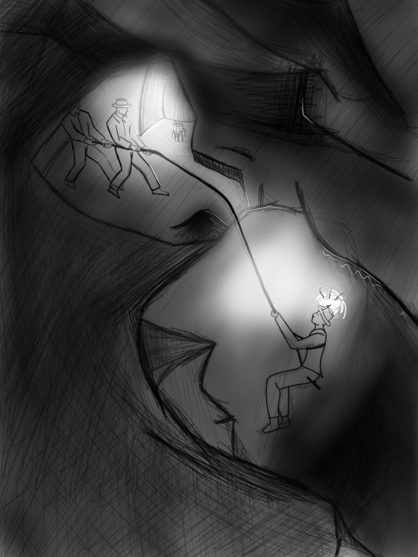
Using a rope attached to a person or object, and paying out the rope so that they descend a pitch. For lowering a relatively light load such as a tackle bag, this may be done simply by holding the rope, and allowing it to slide at a controlled speed through hands.
Lowering cavers was one of the earliest approaches used to descend pitches. This might traditionally have been done using a winch, manual strength, or by wrapping the rope around a tree or some other convenient natural to add some friction. Lowering cavers using manual strength without any other equipment is extremely hazardous, and should be avoided. If a cave is accessed by lowering cavers without using a winch, then getting back out again will normally require hauling, which is much harder. For caves with multiple pitches, teams would need to be stationed at the top of each pitch, so the total team becomes progressively larger.
Lowering a caver might still sometimes be needed for improvised rescue purposes or while using a lifeline, but this should be done using a descender, belay device or Italian hitch to control the speed. Pitches which are configured for indestructible rope technique might sometimes be set up with a lot of excess at the pitch head, with the main rope connected to a locked off descender at the anchor there. If someone needs to be lowered, the lock can be removed, and the descender can be used to lower a caver down the pitch. This approach cannot be used with Alpine rigging except on the most simple of pitch rigging. It is more commonly used in the sport of canyoning, when leading an untrained group who might need to be lowered in an emergency.
This section concentrates on people being manually lowered into caves, or being lowered into caves where the method used is not known. See the section about winches for more details about their use.In the cliffs above Lastebasse in Val d'Astico Italy, a cave called Covolo di Pisciavacca (meaning "cave piss-cow", previously Covolo di Rio Malo, meaning "cave river bad") was used as a fortified toll house, for collecting tolls from travellers as they passed from one territory into another. It was probably set up before 1000 CE when it was part of the Holy Roman Empire, and was used until it was taken over by Austria in 1509, having had a brief administration by the Republic Of Venice shortly before the end. The cave had no means of access, and it needed people to be lowered and hauled using a rope. The research did not reveal whether it had a winch or whether lowering was done manually, and there is no remaining evidence at the cave, but it held around 30-40 soldiers, so either method is possible. It is not known how people were connected to the rope.
In 1615, the fictional story Don Quixote by Spanish author Miguel de Cervantes included a description of being lowered into the real cave Cueva de Montesinos. In 1630, a coal miner was lowered 35 metres twice into a cave called L'aven du Curé or L'aven du Capelan, to retrieve the body of a murdered priest. It is not stated whether a winch was used. In 1667, British Royal Society writer Thomas Sprat published a report that described merchants being lowered into a 9 metre deep lava cave on the flanks of Pico del Teide in Tenerife, Canary Islands, Spain, by servants. The exact year that this took place was not mentioned. In 1676, British geologist John Beaumont was manually lowered using ropes into Lamb Leer Cavern's Great Chamber as part of mining operations. In 1682 British captain Greenville Collins descended Pen Park Hole in Bristol using ropes and sailor's pulleys. In 1723, an unnamed farmer, monk Lazarus Schopper and butler Johann Zouhard were lowered 58 metres to the floor of Propast Macocha (Macocha Abyss) in the Czech Republic, using a manually lowered rope with a boatswain's chair made from a (presumably wooden) peg that was driven through the rope. The rope was wrapped around a tree for friction. (Some reports suggest that it was used as a ladder with several pegs, but this is not what the original text says). In 1776, Ivan Lovrić and two locals were lowered down a 17 metre pitch in Gospodsku Špilju, Czech republic.
In 1785, French abbot Charles Carnus descended Tindoul de la Vayssière, being tied to the end of a rope and lowered by assistants using only the strength of their arms. In 1795, a member of British clergyman William MacRichie's group was lowered into Jingle Pot, without reaching the bottom. In 1796, an unnamed German man was lowered 34 metres into Adernzopf in Germany, to see if it could be used to hide belongings from French invaders. In 1829, a miner was described as having been recently lowered into a cave referred to as the Sandford Gulf, which is likely to be Mangle Hole, Triple Hole or Sandford Levy, without reaching the end. The depth of the cave was given as the length of the sloping passage, so the actual depth is not known, but Mangle Hole's sloping 53 metres is a good match, and the location is correct too. The exact method is not described, but it was normal for miners to use winches at that time. In 1840, Americans Mat Bishop and Stephen Bishop were lowered to the bottom of Mammoth dome, Mammoth Cave by 4 or 5 tourists. In 1842 and again in 1843, British caver John Birkbeck was lowered half way down Gaping Gill's Main Shaft on a rope by farm laborours, ending at Birkbeck's Ledge. The same approach was repeated at the nearby Long Churn Cave to nearly reach the bottom of Alum Pot in 1847, with a team consisting of John Birkbeck, William Metcalfe, William Howson and 7 others, with William Howson being the only one to reach the pitch base of Alum Pot. In 1858, American boy William Courtland Prentice was lowered into Maelstrom, Mammoth Cave.
In 1875, British caver Joseph Plumley was lowered into Plumley's Hole, and was killed when the rope pulled him into a narrow cleft while being hauled back up. Ropes were used in France to lower cavers into caves since 1879. In 1880, after British miner Andrew Lyons and two others rediscovered Lamb Leer Cavern, Andrew Lyons was lowered into the Great Chamber on a rope by other miners, without using a winch. Two weeks later, Joseph Nicholls and James McMurtrie were also lowered into the Great Chamber by 5 miners, without using a winch. In 1882, Joseph Nicholls and Walson Richards (a newspaper corespondent and the only non-miner) were lowered into Cave Of Falling Waters chamber in the same cave (though they treated it as a rope climb on the way out, and the description fails to say that they were lowered). In 1885, ropes were used to lower a hired worker and/or Absalom Shirk Lehman into Lehman Caves in Nevada, USA. French caver Édouard-Alfred Martel was lowered into several caves, starting from 1888 in the Grotte de Dargilan. This would normally take a team of 6 people, but this could be reduced to 4-5 people when a pulley was used. He would typically use a boatswain's chair made from a rope tied to a stick. In 1900, the Kyndwr Club descended Eldon Hole using a boatswain's chair lowered on a rope fed through a pulley. In about 1907, British caver Ernest Albert Baker of the Kyndwr Club was lowered manually into Coral Cave by 3 people.
While this approach is now relatively infrequent, its use continued sporadically, particularly for rescue purposes. Between 1901 and 1914 there were two related incidents where someone had tried to climb down the Forty Foot Pot in Swildon's Hole in Britain, and had to be hauled back up. Another incident took place during a flood in Eastwater Cavern in Britain before 1914, where hauling was used to ascend a pitch to avoid a flooded route. In 1956, a member of the British Wessex Cave Club was lowered down a well in Gambia (now Republic Of The Gambia), Africa, to rescue a lamb. The well was humorously referred to as Lambs' Lair 2. Casualties were hauled up pitches in Britain by the Mendip Rescue Organisation Swildon's Hole in 1956, Easterwater Cavern in 1957, and Swildon's Hole again in 1959.
This history section only covers lowering. This article also has a detailed history of many of the other devices and techniques that are used for vertical caving.
Manually pulling a person or equipment up a pitch using a rope. This is commonly done while derigging a pitch, lifting tackle bags containing previously derigged rope. For light loads, it is common to simply pull up the rope using hands. However, for heavier loads, a progress capture pulley, or a combination of pulley and ascender, might be used to avoid dropping the tackle bag back down the pitch, and having to start all over again. This is only possible for pitches with no rebelays or deviations, and lowering the rope back down again risks accidentally catching it on a ledge so that it does not reach the bottom, leaving other cavers stranded. So except in the case of derigging, it is an approach that should not be relied on, and cavers are normally expected to take their tackle bags up with them while prusiking.
Manually hauling a person was traditionally one of the main ways to ascend a pitch, and might still be used in improvised rescue and organised rescue. This requires a lot of strength, and is prohibitively difficult for long distances. It comes with the very severe risk of running out of strength, and dropping the person, so an ascender, belay device or other progress capturing device is essential. To avoid both problems at once, a Z-rig might be used, since that reduces the strength needed, and also saves the progress. However, it does so at the expense of speed. In general, hauling people up pitches should be seen as an absolute last resort, to be used for rescue purposes only.
Silly rope techniques. Wait. Was that right? Oh. Sorry. Single rope techniques. Abseiling and prusiking. A way of navigating down or up a pitch. Also known as "swinging around on silly bits of string". By far the dominant approach used in potholes, as it allows routes to be created away from hazards. Somewhat slower to rig than using ladders, and requires significantly more training, but provides better safety at a pitch head, and does not need a belayer. Requires more equipment than ladders for a cave with only one or two short pitches, since each person needs their own SRT gear. However, once pitches become larger, or if a cave has several of them, SRT requires far less equipment. Sharing SRT gear is not advisable, since it is usually tailored to the needs of a specific caver, and can get snagged on the walls of a pitch when hauling or lowering it. With SRT, the rope remains rigged on the pitch, while the caver and their SRT gear moves up, down or sideways along the rope. This is different from using a lifeline, winch, hauling or lowering, where the rope also moves as the caver moves.
This section concentrates on the use of SRT in caving, with a few mentions of some early devices, rope access and arboriculture. See the sections on abseiling, body abseil, descenders, prusiking, ascenders and the Prusik knot for more details of the specific methods and devices that were used for SRT in general.
The original use of ropes in caves for cave exploration purposes is as handlines, as well as lifelines for ladders once they started being used underground. Prehistoric cave paintings from about 12500 BCE in Atxurra, a cave in Spain, show that explorers were visitng a part of the cave that was quite challenging to access. Geomorphological analysis of the cave showed that the route through the caves, as it would have been at that time, will have needed some kind of assistance for nearly vertical sections. Ropes are most likely to have been used as handlines. In 4200-2700 BCE, Neolithic miners at Rijckholt Flint Mine (now Netherlands) are thought to have used ropes as handlines to access their mines. A depiction of the Greek myth of Orpheus created on a hydria (water carrying jar) in 440 BCE, shows a rope being used to retrieve the head of Orpheus from within a cave. While the myth has no basis in reality, the actual cave where this myth is thought to be based, Σπήλιος ("Spilios" or "Speleos" - meaning "caveman") on the island of Λέσβος (Lesbos), was certainly visited by Ancient Greek visitors, and they may have created the myth based on their actual use of the cave. Ropes are not currently needed inside the cave, but handlines would have been useful for the climb up to it. The floor of the cave is not natural, and originally could have had a deep hole in it, where ropes may have been used. Either way, in 440 BCE, someone thought handlines were needed in caves.
Ropes have likely been used for hundreds of years to access caves during mineral mining operations (as early as 4000 BCE in southern Britain and 1500 BCE in central Britain), for mining guano or for collecting birds' nests (as early as the year 800 in southeast Asia). However, they did not often keep records of what caves they visited, or whether they descended them using ropes, or what techniques were involved. There is a legend that in 1122, Għar Ħasan cave in Malta, Kingdom of Sicily (now Republic of Malta) was home to a Saracen (meaning North African Arab or Berber) called Hasan, who had not left the island when it was taken over. In some versions of the legend, he would climb a rope up and down the vertical cliff below the entrance to a boat. In other versions, he lowered a kidnapped woman on a rope down to a boat. However, while this would have been an impressively early record of a rope being used to access a cave, there is no evidence for the urban legend in spite of repeated archaeological excavations, and the cave had always been accessed by walking along a ledge instead. The cave was first mentioned in text four centuries later, with its legendary inhabitant mentioned as an Arab five centuries later. The story remained that simple into the mid 1800s, and the earliest written reference I found to the rope part of the story (or his victim) was the mid 1900s, presumably introduced to boost its popularity as a showcave. The name simply means Inaccessible Place Cave, rather than being a person's name. Methods to control descending on ropes had existed since before the 1500s, but it took a while for these to be used in caves.
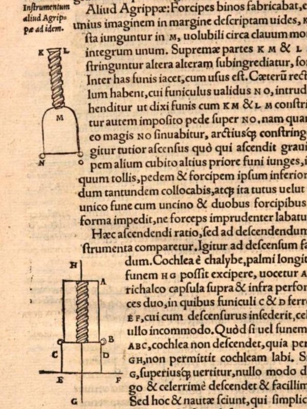
Ropes have been used for access work, particularly the building trade, for so long that there is no record of when it would have started. In 170-180 CE, Ancient Greek author Claudius Galen described in a health guide intended for the whole Roman empire, De Sanitate Tuenda, book 2, chapter 9, how climbing ropes was used for fitness training. The rope was fixed at the top and the ground, and was held in the hands. It does not mention whether the feet were used. In about 1460, Aeneas Silvius Bartholomeus Piccolomini (better known as Pope Pius II) wrote Epistola CCCCXXVI (letter 426), "De crudeli amoris exitu Guiscardi et Sigismundi Tancredi salernitatorum principis filie", which was a modified version of the fictional story of Tancred and Gismund. In his version, the prince sneaked into a woman's bedroom via a cave, which he had to climb in and out of, using a handline. In 1479, Scottish prince Alexander Stewart slid down a rope made from bedsheets to escape from Edinburgh Castle, but the exact method was not described. Between 1495 and 1497, Leonardo da Vinci designed a mechanical ascender in the Holy Roman Empire, now Italy. Sailors from the 1500s to the 1800s slid down ropes which they gripped with their legs, and either slid their hands down, or gripped the rope one hand at a time. In around 1520-1530 Heinrich Cornelius Agrippa von Nettesheim developed both the earliest known descender and ascender in the Holy Roman Empire (now Germany), and used rope walking. He is therefore likely to be the first person to use both abseiling and prusiking, and therefore could be considered to be the first person to use SRT.
King Henry VIII was still married to his first wife. The Mary Rose was still floating. The Royal Navy did not exist yet. Pikes and bows and arrows were still the primary weapons of war with matchlock guns still being secondary support. William Shakespeare's grandparents were probably just getting married. Written English had only just become recognisable, and spoken southern English still sounded like a strong Geordie accent. Greensleeves, probably the oldest secular English song you know (unless you know Sumer is icumen in), still would not be written for another half a century, and music still sounded positively medieval. It would be hundreds of years before Baroque and classical music would appear. Martin Luther had just published his protestant thesis against the Catholic Church and ignited the Protestant Reformation. Michelangelo had recently painted the Sistine Chapel. Niccolò Machiavelli had not yet offended the entire world by encouraging morally corrupt tyrants. European commoners were still not legally allowed to wear bright colours, because they were reserved for the wealthy elite, and it would be centuries before that changed. Spain had just started the very first Caribbean colonies and Hernán Cortés had just taken over the Aztec Empire in Mexico. Tomatoes, potatoes, sweet potatoes, corn, quinoa and related grains, peppers, Jerusalem artichokes, sunflowers, cassava/yuca/tapioca, most beans, peanuts, squashes, pumpkins, courgettes, pineapple, avocado, papaya, guava, chayote, chocolate, vanilla, tobacco, turkey and guinea pigs were unheard of in Europe, Asia or Africa. They had not yet llearned about llamas. Horses, donkeys, cattle, sheep, pigs, chickens, cats, European dogs, wheat, oats, barley, rye, millet, buckwheat, coffee, carrots, cabbages, spinach, chard, beetroot, turnips, radishes, mustard, cucumbers, aubergine, onions, garlic, lettuce, apples, citrus fruits, bananas, figs, olives, sugar, butter, cheese, iron and steel were only just being introduced to The Americas. Portugal had taken over and started to increase the West African slave trade, and recently claimed parts of Southeast Asia and Brazil, discovering penguins on the way. The Pacific Ocean had only just been found by Europeans and was in the process of being crossed by Ferdinand Magellan for the first time. North America's population still consisted of 20+ million native Americans and twice as many bison. The English owned half of the British Isles and the tiny Pale of Calais, and not an empire. The French had not planted their first foreign flags. The Dutch didn't even own The Netherlands. The Ottoman Empire was busy becoming a superpower in the Mediterranean after taking over from the Byzantine Empire. The Mughal Empire was only just beginning and had not yet united India. Indian curries used mustard, ginger, black pepper and its relative long pepper, but without the characteristic chillis, they were not really hot yet, and neither was other Asian food (except wasabi in Japan); European foods made with horseradish were hotter. Guru Nanak was establishing Sikhism as a new religion. The dodo had not even been found or named by humans yet, and was blissfully unaware of its impending dodoom. The Australian continent still would not be known by Europeans for a century, and Antarctica would not be found by anyone for three. Marsupials like opossums and kangaroos remained unknown to Europeans. Russians would not find out that they had a northern coast for well over a century, and did not yet know why their leader's future son Ivan was Terrible. And yet in Europe, SRT was already in use, and people were already swinging around on silly bits of string!
German explorer Berthold Buchner wrote about an expedition to Breitenwinner Höhle, a cave in the Holy Roman Empire (now Germany), which was published in 1535, but the date of the expedition is not known. Ropes were used to descend some steep parts, presumably as handlines and lifelines, and this is the first known written account of ropes being used for cave exploration purposes. Since then, ropes continued to be used the same way, but with developments soon including manual lowering or the use of winches. In 1556 (but researched from 1528-1550), the book De re metallica (on the nature of metals) listed how metal mining was carried out in the Holy Roman Empire (now Germany, Czech Republic, Austria and Italy) and Hungary (now Slovakia). It described and depicted how miners would sometimes slide down sloping mine shafts "sitting on leather" as a sledge. To control their speed, they would run the rope under their armpit like a body abseil. Sailors in the Holy Roman Empire (now Italy) were experimenting with a simple stick descender in 1549-1550, as described by Gerolamo Cardano. Separately, he also described how a person could lift themselves more easily using doubled rope technique, and used counterweights to make it even easier. This is the first known mention of doubled rope technique, but it is likely to be older, possibly used by various industries during previous centuries.
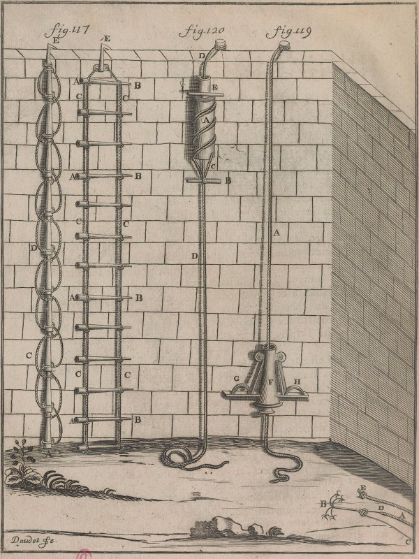
Polymath Galileo Galilei described an early descender in 1638, in what was then the Republic of Florence, Holy Roman Empire, now Italy. French inventor Nicolas Grollier de Servière improved Galileo Galilei's descender, and created a clamping jaws ascender, with which he developed prusiking using just one ascender. He is therefore the second known person to use both abseiling and prusiking, which he suggested could be used for castle invasions and rope access. The date of these events is not recorded, but was during his retirement, which began in 1642 and ended with his death in 1689. It is likely to have been shortly after obtaining the 1647 French translation of a book by Galileo Galilei. Details were published in 1719.
French roofers and plumbers have been described using a knotted rope to climb buildings from as early as 1684, though the technique is almost certainly much older, as roofers had been described as "dancing on ropes" and "holding firm at places they pass" by René Le Pays in 1664. The technique was described rather poorly in 1723, and described and clearly depicted in two separate publications in 1762. They would stand in footloops which they attached using suspension hooks hooked above the knots of a knotted rope, alternating from one footloop to the other while moving the hooks to the next available knot, and holding on with their hands. This could be used to climb upwards or downwards. This method was described being used by French exterior decorators in the early 1800s, and continued to be described into the 1900s. It was known as "echelle de corde" (rope ladder), "echelle de couvreur" (roofer's ladder) or "corde nouée" (knotted rope), sometimes using the older spellings eschelle or echele. This would later inspire some forms of prusiking.
In 1669 a quarry worker broke into the top of Pen Park Hole in Bristol (directly at the top of the Main Chamber). British captain Samuel Sturmy and a miner named Dick explored the cave by lowering themselves down the 40 metre pitch on ropes which were attached at the top of the pitch, and climbing into the lower parts of the cave. The pitch is partially sloping, and partially vertical. They used ladders to reach side passages, but both descending and reascending the pitch was done using ropes. The technique for descending the ropes is not specified, but will have involved a combination of handlines and hand over hand body abseil. Ascending involved climbing the rock with a handline, and rope climbing.
In 1717, French botanist Joseph Pitton de Tournefort visited Σπήλαιο της Αντιπάρου (Cave of Antiparos) in Greece, using ropes as handlines. In 1725, German engineer Jacob Leupold from the Holy Roman Empire (now Germany) improved Nicolas Grollier de Servière's prusiking system, adding a second ascender. It was suggested as a way to escape a fire using a rope, by reverse prusiking. In 1769, a mathematics book (published under a few different names) by British author William Emerson described steeplejacks or builders working on masonry using doubled rope technique with pulleys arranged to gain mechanical advantage. In 1778, Johann Georg Krünitz described in Berlin, Prussia, Holy Roman Empire (now Germany) in the Oekonomische Encyklopädie volume 13, how mountaineers were using doubled rope technique to lower themselves using hand strength. Marie-Gabriel-Florent-Auguste Comte de Choiseul-Gouffier revisited Σπήλαιο της Αντιπάρου in 1782, and again with Elisabeth Craven in 1786, at which time guided tours were being offered, using handlines to descend into the cave. In 1787, Genevan mountaineer Horace Bénédict de Saussure used a walking pole as a descender, while descending from Mont Blanc in the French Alps. In 1793 Rosenmüllerhöhle was explored by German doctor Johann Christian Rosenmüller, using a rope for the surface shaft. Since abseiling and prusiking were not used in caves in that era, it is likely to have been a handline only. From 1793 onwards, several books taught sailing rope climbing and descending techniques to gymnasts. In 1794, an anonymous visitor to an active Cornish mine in Britain described using a rope as a handline to descend a narrow mine shaft. Some time before 1824, French arborists developed a method to climb trees or poles using metal spikes called "tree climbing spikes" or "spurs" attached to their feet (known at the time as "climbing-spurs" in English, or "griffons" meaning "griffins" or "griffes" meaning "claws" in French). They dug them into the wood, while they would grip the trunk with their hands. Telegraph workers then used the same approach for climbing telegraph poles. This method is not used in caves, but it would later inspire a form of prusiking.
Italian/Austrian mining engineer Antonio Federico Lindner and water management engineer Jakob Svetina explored Grotta/Abisso di Padriciano/Šeštajevka Jama (then the Austrian Empire, now Italy) in 1839 using only ropes, searching for a water supply. Over a few trips, they reached a depth of 220 metres, descending steep sections and free-hanging pitches (including one of 45 metres in total height), presumably just using strength to climb the ropes! By 1840, French arborists would tie ropes around a tree trunk for safety when resting, but only at the protest of those who preferred to climb without it (this approach was mentioned in 1874 in an unspecified country, 1881 in France and 1883 in Britain). In 1841, Belgian arborists were described using a rope as a flipline when climbing with tree climbing spikes, for pruning trees. The method is not described in detail, but there is enough to know that it is a flipline, as it says that the person "ascends by the assistance of a cord and climbing spurs" by "passing the cord round the stem" of the tree. In normal use, a loop of rope is passed around the back of the tree for grip, and is either tied to their belt at each end, or looped behind their back. They lean back on the rope, step higher using the spikes, lean forward, shake the flipline a little higher with their hands, and repeat. A great many modern tutorials claim that this is the oldest method of climbing trees, but the flipline is a later development than the tree climbing spikes. Many other methods of climbing trees were in use long before either fliplines or tree climbing spikes, such as rigid ladders (both on the ground, and resting on branches to reach higher ones), ropes and manual climbing. The Romans are thought to have used these methods for arboriculture throughout their empire around 2000 years earlier, and they had been used continuously ever since. In 1845, miners, well diggers and mountaineers in Britain were described using doubled rope technique to both lower and raise themselves, and the same approach was suggested for a fire escape. In all cases, ascenders were not used, and the rope was pulled by hand.
In 1851, fire brigades in Ulm, German Confederation (now Germany) were abseiling with a ring attached to their belt like a carabiner wrap, but an actual carabiner was not yet used for that purpose. By 1855, British egg collectors (who would now be considered egg thieves, and incredibly harmful to wildlife, but who delusionally considered themselves to be ornithologists at the time) were using tree climbing spikes to climb trees, without using fliplines. From 1860 onwards, many descenders were invented, particularly in the USA, for use as fire escapes, with over 150 registered designs in several countries by the 1900s. British mountaineer Edward Whymper used ropes as handlines while climbing in 1862. In 1863, Scottish steeplejack and former sailor James Duncan Wright, better known as Steeple Jack, prusiked up a lightning conductor on a steeple, using the same basic idea as the French exterior decorators, but using a noose as a friction hitch. This technique was then used to prusik up flagpoles, becoming popular in the USA by the end of the century. By 1863, the damage caused by tree climbing spikes was already noticed, and the use of tree climbing spikes and fliplines was reduced. However, in 1865, naturalists trying to study animals would use tree climbing spikes and ropes to climb trees. The exact method of using the rope was not described, but it may have been a handline or a flipline. By 1872, the Austrian fire brigades were abseiling with their belt rings for self rescue. In 1874, British egg collectors described using a substitute flipline made from thin tree branches or iron, combined with tree climbing spikes. In 1875, British caver Joseph Plumley was lowered into Plumley's Hole, using the approach commonly used by miners at that time, which was to have a separate handline in addition to the hauling rope. Before 1875, ropes had been used by American egg collectors. The method used was described in 1885 as pulling thin trees over with a rope until the eggs could be reached from the ground. In 1875, they were described as climbing with tree climbing spikes (which they called climbing irons or climbing spurs), without using a rope to climb the tree. In 1876, French mountaineer Jean-Estéril Charlet-Straton slid down a handline the way that sailors and gymnasts had already learned not to do because it could cause injuries.
In 1877, American egg collectors were described as using a rope to rest when climbing a tree using tree climbing spikes, the way it had been originally described by French arborists. They were also described as using a flipline without tree climbing spikes. In 1878, they were described by American egg collector Fred J. Davis as being used with a flipline on big or smooth trees. From that year, arborists from many countries were shunning the use of tree climbing spikes for the lasting damage that they caused to trees, which spoiled the timber produced by them as they healed around the damage. Their use in Europe and European colonies was limited almost entirely to felling trees, while many American arborists continued to use them extensively for several decades for maintenance work, still damaging the trees. By 1878, fire brigades in southern Germany were abseiling using an actual carabiner wrap. German inventor Ed. von Mengden created clamping jaws mechanical ascenders for telegraph poles in 1878 to avoid the damage from tree climbing spikes, and on ropes in 1879 (but not for caving), using two different prusiking systems, one of which was new. Ropes were used as handlines for tourists in Lehman Caves in Nevada, USA, in 1885. In 1893, Swedish inventor Anders Wilhelm Lewin created a device that could be used as both an ascender and descender. Several other devices appeared during the 1880s and 1890s. In 1893, an American children's magazine documented the use of a doubled gantline by sailors to haul another sailor up on a boatswain's chair, after which they could temporarily tie it to a cleat on the chair and lower themselves with it, the earliest known definitive mention of doubled rope technique used by sailors. It is not known if this practice started before or after its use by mountaineers in the previous century. In 1884, an American egg collector identified only as "J. M. W." used a fire escape system for climbing a rope which was thrown over a tree branch, and climbed using doubled rope technique. The fire escape they used essentially consisted of a descender rather than an ascender, and would have been very clumsy to use as an ascender. It was also only a single ascender, so some other method of support would still have been needed while sliding it up the rope, such as standing on branches. Nevertheless, this is the earliest known use of SRT to climb a tree. (Presumably, they were trying to hide their actual identity to avoid being shunned for their actions, which were already recognised as harmful. Trade in wildlife would become illegal in the USA in 1900 under the Lacey Act, and egg collection would be more specifically banned in 1918 as part of the Migratory Bird Treaty Act.)
In 1891, American arborists in Massachusetts were photographed trying to eradicate a gypsy moth infestation from a tree. They used ladders to reach some branches, but for others, arborists can be clearly seen being hauled up on a boatswain's chair, with a series of pulleys to make it easier. They can also be seen resting on the boatswain's chairs in order to work on the tree. In 1896, French arborists were using ropes looped higher up around the trunk, which would be tied or clipped to themselves (sometimes via a tether) using carabiners, to support them as they walked out onto lower branches. Climbing the tree would still be done manually, or using ladders, or by hanging steps off ropes tied around the trunk. German and French arborists both, however, were still depicted as using the same arrangement as a flipline for resting while pruning trees in 1896. In the same year, American arborists were known to have used ropes to tie a wooden platform to a tree so that they could use it for work, but roped platforms and the use of boatswain's chairs were both very uncommon in American arboriculture, and most American arborists would not use ropes. American William E. Burke used clamping jaws ascenders for rope access in 1897. By 1897, German mountaineers had started using body abseil techniques to descend after a climb, with over 15 new techniques developed over the next 45 years. In 1898, the British publication The Boy's Own Paper included a memoire called Old Portsmouth by George Andrew Patterson. This included a description of a sailor using doubled rope technique with an adjustable hitch to control the position of a boatswain's chair, which he was using to slowly descend a ship's mast after being hauled up it using a gantline. While it does not mention which hitch was used, one knot that was known to be used for this purpose with hawser laid ropes is a lark's foot tied in the down rope around the strands of rope that hold the sides of the seat (known as a lowering hitch in this configuration), where feeding rope in from the tail of the lark's foot allows a controlled descent. The account seems to be based in fact rather than fiction, and would have happened around the time that the story was written. This approach was not mentioned in relation to American sailing but was stated by the British Admiralty as being used extensively by the British merchant navy in 1952, so the use of a lowering hitch seems to have been a recent British development before 1898.
In 1901, New Zealand inventor Robert Cockerell invented a lever cam ascender and descender, and reinvented a much older prusiking system, not aimed at caving, but his inventions would later be used by cavers. Clamping jaws ascenders were in use in the USA again in 1902 by Charles E. Knop and 1910 by Iver J. Westad, neither of which were aimed at caving. In 1903, British inventors P. and W. MacLellan and James Dougall also used them for a prusiking and abseiling device, not aimed at caving. In 1904, a lever cam device was patented by Austrian locksmith Michael Gayer, which was marketed to climbers in that year as a fall arrester for self belaying when climbing, but which could have also been used as an ascender. In 1905, steeplejacks in New York had developed the Texas system as a safer way to climb flagpoles for painting or servicing, called steeplejack's flagpole slings. In 1918, this was recommended by the USA government to all steeplejacks. German mountaineers H. Sixt and Franz Kröner created a lever cam device for mountaineering in 1911, called a "climbing lock". It was intended to be used as a self belaying device while abseiling, but could have been better used as an ascender. In 1912, 15 year old French caver Norbert Casteret descended and ascended ropes in the Gouffre de Planque, including a 35 metre free-hang, just using strength to climb the ropes. He continued caving that way for 20 years. In 1913, Austrian inventor Johann Machek prusiked using a boatswain's chair below the ascender, but this was not used in caves. By this stage, prusiking was in use in several European countries, North America and Australasia, for rope access work (well digging, exterior decorating, building work, quarry work, fire service, etc.), on a relatively small scale. In 1913, American and Canadian lumberjacks were climbing extremely large or tall trees to cut the tops off them, and connect cables or ropes to them for use with logging for timber. This job was known as a high rigger, high climber, topper or top rigger, and had probably existed in some form since the first few years of the 1900s. Although the methods were not described at the time, they were described in 1916 as using tree climbing spikes and fliplines. The flipline was only described as being for safety, but it was actually essential to the process. By 1923, this was already being used for speed climbing races in American carnivals dedicated to lumberjacks (yes, those were a thing!). The actual climbing method was filmed in 1929, showing that it was definitely a flipline.
In 1917, American arborist Leeman F. "Lem" Strout (frequently mis-spelled Lem Stout) is said to have been the first in America to use a climbing line. In current arborist usage, that term refers to a rope that is used for doubled rope technique or stationary rope technique. However, the details of its use by Leeman F. "Lem" Strout are stated incorrectly in virtually all publications, which simply repeat the same mistaken statement almost word for word, while making the same mistake with the spelling of his name, so presumably none of them have actually read the source material, and just copy each other. Despite his claims of being first to use ropes in a tree, others had already been doing so for nearly a century, with some usage dating back 3500 years. Ancient Greeks and Minoans had used ropes to hang their swings from trees since 1450-1300 BCE, and deaths by hanging using ropes in trees was well enough known that it appeared in the Greek play Antigone by Sophocles in 442-440 BC. German children were depicted using ropes to climb trees for exercise in 1793. By 1917, French, Belgian and German arborists had already been using ropes for resting, safety and actively climbing trees for nearly 80 years. They had even developed new techniques over the last 20 years. American egg collectors had been using ropes in trees for many decades, for resting in trees for 40 years, and as fliplines for climbing trees for nearly 40 years. Polynesians had done so for well over a century. Even Roman arborists are thought to have used ropes for climbing trees around 2000 years earlier. Some American arborists from the same region had been hauled into trees using ropes over 25 years earlier, in the same city as Leeman F. "Lem" Strout's first arboriculture job, which was also removing gypsy moths. American lumberjacks, whose job was to cut down trees for timber rather than look after them, had been using ropes for several years too. American arborists were just very slow at realising that ropes had already been used in trees for many decades, and that better and much safer techniques existed than they were using. Apparently there was no communication between American lumberjacks and arborists, or even American arborists and other American arborists, who worked in the same city! It is important to note that Leeman F. "Lem" Strout was not even the first arborist in America to use ropes, and not even the first Arborist in his region of America to use ropes, and may simply have been the first of the arborists that he knew at the Francis A. Bartlett Tree Experts Company that he worked for.
The original source of the myth is an article series that he wrote called "The Good Old Days" in the publication "Tree Topics" by the Bartlett Tree Experts, originally published in 1957, and republished in the spring edition in 1992. In that article, he did not in fact state which years anything happened, and 1917 was probably just assumed by a reader subtracting "when I started in business more than 40 years ago" from 1957, as if it happened at the start of his career, when he was still an apprentice, defying the orders of his instructors. Clearly unlikely, since if anyone were to make a sweeping change to the way arborists worked, it would have been after several years of experience, when they had some authority. He stated that while he "was first to use a rope in a tree" (an astoundingly arrogant claim, given mountains of evidence to the contrary), he did not initially use it to actually climb the tree. He used 6.4 mm clothesline, and only used it for holding a paint bucket, not for climbing! At a later date, the whole team then used 12.7 mm ropes for climbing trees, and the article does not make it sound like they used doubled rope technique or any form of prusiking. From the description, it seems likely that they simply used them as handlines. The article says that Leeman F. "Lem" Strout was one of the people who wanted to use ropes (after breaking a tree climbing spike by jumping down to a lower branch), but it does not say who actually used them first for climbing. His poorly written, rambling text may have been trying to imply that he used his bucket rope for that purpose, but it was not written clearly enough to know. This event, where he must have had some influence to dictate a change in practice within the company, is far more likely to have been around the mid 1920s than 1917. Once they were in use, ropes soon replaced the use of tree climbing spikes. By 1918, it was already common for rope access work to use doubled rope technique with a boatswain's chair for both raising and lowering, and this did not originate with arborists. It was not stated how to capture the raising progress, but the suggestion was that this should be done by the person raising themselves.
A more complete approach to SRT in caves started in France. Cavers first started making mechanical ascenders in 1920, starting with Léon Pérot's prototypes, which were apparently never used underground. French exterior decorator Antoine Joseph Marius "Paul Cans" Barthelemy created his Ouistiti (marmoset) ascenders in the same year, using an approach clearly adapted from Johann Machek's, and demonstrated them in 1921, but these were not used in caves. William Dallimore stated that British arborists were sometimes using ropes as an aid when climbing trees in 1926, but did not say exactly how they were used, and did not describe anything similar to SRT, suggesting that they were only used as handlines. During the late 1920s, the Dülfer-Kletterschluß body abseil had been described in Germany by Zsigmondy/Paulcke, and the classic abseil had been developed by Italian climber Tita Piaz, both of which were later used by French and American cavers respectively. French mountaineer E. Gérard invented the Gérard hitch in 1928, and described how it could be used with the Gérard Alpine technique, and while his hitch was largely ignored, his prusiking technique would inspire most of the prusiking systems that would subsequently be used for caving. His article was translated into English and reprinted in the Alpine Journal in 1929. The Austrian mountaineering journal Österreichische Alpenzeitung then included an article about it in December of 1929. Astrian mountaineer Karl Prusik would have read that journal, since he was a prominent member of the Österreichischer Alpenklub that published it, and his club also distributed the two earlier publications that contained details of it. French caver Henri "Kiki" Brenot developed the Singes Mécaniques (mechanical monkeys) ascenders in 1929, for mountaineering. He then invented the highly advanced Frein de Descente descender in about 1930, which functioned like a rack, and was the ancestor of the modern Simple and Stop. After the reinvention of the Prusik knot by Karl Prusik in 1931, which was evidently plagiarised from E. Gérard's work, it was the mountaineers who made most use of SRT, ignoring the mechanical ascenders that had been developed (because they did not work on ropes that swelled when they got wet), and typically using body abseil.
Henri "Kiki" Brenot and French caver Pierre Chevalier first used the Singes Mécaniques underground in the Félix-Trombe cave system in the French Pyrenees in 1934, descending using a body abseil. The exact method is not recorded, but it was almost certainly the Dülfer-Kletterschluß body abseil, as only two methods were known by French cavers by 1944, and only one of them was suitable for this sort of use. The Puits du Plantillet (Félix-Trombe cave system) in the French Pyrenees was the first cave explored using SRT, by Pierre Chevalier, Gabriel Dubuc, Guy Labour and Félix Trombe in 1934. The Dent de Crolles system in the Grenoble region became the major focus of its use in 1935, by Pierre Chevalier, Hélène Guillemin (most likely the first woman to use SRT, both abseiling and prusiking, in a cave) and François Guillemin, starting with the Trou du Glaz. They frequently used body abseil techniques, and while all three of them used the Singe Mécaniques ascenders as handholds on one rope climb during the first trip, for subsequent trips, they primarily used ladders for ascending pitches, with only one person prusiking up to rig the ladder. A couple of other cavers took part later that year. They were the first to use the approach of trying to get every member of the caving team to bottom the cave, while previous vertical cavers had prioritised one person, with the rest of the team merely waiting at the top of pitches to help that person get back up. Other cavers in the Grenoble region continued to use SRT on a small scale, but would often use a body abseil to descend, then pull a ladder up using the rope as a pull-up cord via a pulley for the ascent, and only use the Singes Mécaniques for one person to prusik up and fix the ladder if it failed to pull up correctly. However, the exploration of the Dent de Crolles system stopped using the Singes Mécaniques after 1936, since their creator and members of the French mountaineering/caving club Les Jarrets d'Acier were involved with other projects where they were used instead. Initially, naturals were used as anchors, or pitons that had been placed by others for use with ladders. It is not known when pitons first started being intentionally placed for SRT, but it is likely to have been extremely early on, as they were being actively used for ladders somewhere between 1924 and 1932.
Some time before 1936, American arborists were using the rolling hitch and a variation with an extra turn, which they called a locking hitch, for storing their climbing progress, the first version of doubled rope technique used by arborists. The rolling hitch also gets called a tautline hitch when it is tied back to its own rope, and American arborist Karl Kuemmerling was apparently using the tautline hitch for this purpose in the 1930s, probably as early as 1932, when he developed a sit harness. This was the first introduction of something related to abseiling or prusiking into arboriculture, but it is quite different from standard SRT, as it used a doubled rope. Ascending might still be done by climbing upwards manually using some other method, or they might have pulled on the rope, but the actual method is not known. This idea was brought into British arboriculture in 1936 but most British arborists continued to ignore it, as they preferred to work without ropes. In the rare cases when they did use ropes, it was as a handline only, or to tie themselves to a branch. In 1938, Pierre Chevalier used the Gérard Alpine technique with prusik loops made from strands of the main hemp rope to prusik up a pitch in the Dent de Crolles system after a ladder failed to pull up correctly, which is the first known use of them underground, and also the first known SRT improvised rescue.
By 1939, Italian mountaineer/climber Emilio Comici was using carabiners as a descender, running the rope through them and then over the shoulder and around the body like a classic abseil, known as an over the shoulder abseil (confusing it with one of the body abseil techniques), seat rappel, Swiss seat rappel, seat shoulder abseil or carabiner rappel (confusing it with all the other ways to abseil with a carabiner). This damaged ropes fairly quickly, and required thicker ropes. In fact, with modern SRT ropes, this technique does not work at all, because it relies on the hawser laid rope texture and very wide rope to create enough friction at the carabiner, while a modern rope is too thin and smooth, so it transfers most of the stress extremely painfully to the shoulder. Cavers in the Mendip region of Britain were using abseiling during 1942, using an unknown body abseil which sounds like the rope was simply wrapped around the waist, but ascending ropes was still done by free climbing, or hauling, or a winch. In that region, cavers had been using ladders very occasionally, but vastly preferred using ropes as handlines (even on very demanding climbs that would have been better treated as pitches). In 1944, a sketch by American sailor Clifford Warren Ashley in The Ashley Book of Knots (#480) shows American arborists looping the rope that they were tied to over a branch, and pulling on the other end in order to ascend, with the locking hitch or a Prusik knot used to save their progress. This is the first time they are conclusively shown using this method, rather than manually climbing the tree. By 1944, many Cavers in the Grenoble region of France were actively using Henri "Kiki" Brenot's very well developed ascenders and descenders, but still preferred a ladder for ascending. It was also still normal to use a winch when more cavers were available. Pitons were often used as anchors.
Cavers in America had also historically used ropes as handlines, or for lowering people down pitches, as well as for ladder lifelines. In 1951, American caver Bob Handley and other cavers from West Virginia, USA, first demonstrated abseiling using the classic abseil to cavers, something they had already been using in caves. Others who had used abseiling in caves at that time included American cavers Earl Thierry, Bob Barnes, Roy Charlton and Charlie Fort, typically abseiling down the lifeline that was intended for use with the ladder. However, they still used a ladder to ascend a pitch afterwards. In 1951, Americans and Europeans used naturals for rigging, while pitons were still very common in Europe, and fixed aids such as traverse lines used expansion bolts in Britain. By 1952, Bob Handley and Charlie Fort had also used Prusik knots with the European Gérard Alpine technique in caves with pitches of up to 30 metres. Other cavers including Larry Sabatinos, Bob Barnes and Roy Charlton had all used prusiking, but not underground. All had viewed it as something to use in emergencies, not regularly underground. In 1952, Pierre Chevalier taught vertical caving techniques at l'Ecole Française de Spéléologie in France, but it is not known how much of that related to SRT. Subsequent courses took place from 1959 onwards.
American caver William Franklin "Vertical Bill" Cuddington had attempted abseiling as early as 1951, but simply slid down a rope using a terrible technique. He was later taught classic abseiling in 1952 by Earl Thierry, Bob Barnes and Bob Handley, but they refused to teach him how to prusik, so he learned their technique from a mountaineering book, and first used it in a cave in 1952. Those techniques may have worked, but they were a significant step backwards compared with what had already been developed in France. Though not within caving, carabiners with brake bars already existed in many parts of the USA since the 1930s, and were in use by mountaineers and the military. Although the mountaineering book had described European prusiking techniques, it was significantly out of date (presumably because World War II reduced the flow of information), as German mountaineering manuals had recommended using carabiners with brake bars for abseiling since the early 1940s, and had shown ring descenders since 1913. Over 100 different designs of descender already existed in the USA, and had been actively used for over 90 years as fire escapes, and these included a couple of different designs of racks. Prusiking with ascenders had existed in the USA for over 65 years at that point. Apparently, the American cavers did not notice.
William Franklin "Vertical Bill" Cuddington created leather rope guides for parts of the body to avoid rope burns in 1952. While others shunned the idea of doing big abseils and prusiking, and would use ladders in both cases, he started using both abseiling and prusiking heavily in Tennessee in 1953, and started teaching it to friends. He adopted the seat shoulder abseil in 1953. His ideas and approaches then spread throughout North America. Some cavers experimented with the idea of using a dual rope system with a second rope for safety, either as a lifeline or as a self belaying rope, known in rope access work as a backup line. They quickly found that a second rope often causes the ropes to tangle around each other, especially with bigger hangs, narrower pitches, or in caves with waterfalls, and a tangle beneath a waterfall could easily prove fatal. In 1955, American caver Cord H. Link described the use of the Gérard Alpine technique and Prusik knots in The Troglodyte volume 1 number 9, spreading the ideas further. These are the instructions that would be used in British caving in 1958. Dean Abbott invented the first American caving descender, the Rappel Log in 1955, which was actually created in 1956, shared with a caving club in 1957, and announced to other clubs in 1959. It immediately took over. It could burn ropes severely, and actually once set fire to a rope during use. It was also only usable with the hemp ropes which were in use at that time.
In 1958, the American National Speleological Society sent instructions on how to prusik to British cavers, with cavers from South Wales (who had founded The Cave Research Group which later became the British Cave Research Association) being the first to put it to use. The instructions showed the use of the Gérard Alpine technique with hemp prusik loops. It is most likely that the first British cavers to use this approach were members of the South Wales Caving Club, in Ogof Ffynnon Ddu. This was followed in 1959 by the instructions for the fourth sling variation of the frog system.
Americans started adapting the Gérard Alpine technique into new prusiking systems. Other American cavers started using carabiners with brake bars, which became racks by 1966. The release of the Jümar ascender (later spelled Jumar) in 1958 made SRT more accessible, and cavers around the world started experimenting with it more heavily, but it was about 1965 before they were used for caving in the USA, having only been introduced to the USA in significant quantities in 1963. William Franklin "Vertical Bill" Cuddington stopped using ladders in 1961. The use of spits had started in France with ladders in 1961, and they became widespread in France after 1965. In the early 1960s, Jumars were used in a cave for probably the first time, in Biolet Cave in the Grenoble region of France. During a 1962 expedition by British cavers, mostly from Northern England, to the Gouffre Berger in France, around a fifth of the cavers were happy to use abseiling, but none of them prusiked. David Judson of the Yorkshire Ramblers' Club later stated that prusiking was unheard of at that time, showing that knowledge of it had not yet reached Northern England. In 1962, Wessex Cave Club members Oliver Craig Wells and Derek Ford had tried prusiking using prusik loops in the British Mendip region, presumably only on the surface, but had stated that they were not impressed, and it was better to use ladders. This is the earliest known mention of prusiking in Mendip.
In 1963, the Wessex Cave Club journal included an article by British climber and caver T. Charles Bryant, suggesting SRT techniques that were used for climbing, and could be adapted to caving. However, it was written in a way that suggests that almost none of it had actually been used for caving at that stage, in the Mendip region. The article was written with condescending, egotistical, and elitist undertones, claiming that only rock climbers could be good cavers. It rather insultingly suggested that many Mendip cavers were not competent enough to tie knots, and should use carabiners when connecting to a lifeline to avoid having to tie a bowline. It also said that cavers who were not also rock climbers simply could not cope with heights, and were not very good at climbing, ignoring the fact that Mendip cavers would frequently climb quite serious pitches with nothing more than a handline, and would use ladders at whatever heights were needed. He quite incorrectly stated that prusiking was not likely to be useful for caving, since there is almost nowhere where it can be used, and that ladders are therefore better. Abseiling was stated as being quite common in Mendip, using the classic abseil. Carabiner-based abseils were also recommended. However, descenders were suggested for more advanced cavers, and the terrifying Trevor Peck descender was depicted, that could very easily disconnect from the rope. The knot he suggested to replace the bowline is laughably worse than a bowline, since it is a noose that tightens around the person and can suffocate them if they fall, is far harder to tie, is nearly impossible to recognise whether it has been tied correctly or not, can come accidentally untied almost as easily, and can damage kernmantel ropes. No doubt the unpleasant tone of the article will have put people off, and it will have held back cavers from trying to use more advanced SRT than they had been using. (Although he would eventually join the South Wales Caving Club, that would be several years later, so he would not yet have realised the developments there.)
By 1963, cavers in the South Wales area of Britain were among the earliest in Britain to actively use SRT. They would commonly use nylon hawser laid rope, pitons, climbing nuts/wedges/chocks and slings made from wire cables for naturals. SRT gear consisted of a belay belt or chest harness instead of a sit harness, and a single cows tail. Descending was done using classic abseil or using the seat shoulder abseil, with complaints about the available descenders burning ropes or disconnecting from them. Prusik loops were used, but more for improvised rescue than active prusiking. The prusiking system is not known, but it is likely to still have been the Gérard Alpine technique. Ascending was done using ladders, or etriers and fifi hooks with piton aid climbing. French caver Bruno Dressler made the Simple descender in the Grenoble region of France in 1963. Near the end of 1963, an older Wessex Cave Club caver stated that new cavers should focus on ladder skills instead of abseiling, because that was more important to caving. Cavers from the South Wales Caving Club, including John Victor Osborne, reinvented the hands and feet system in 1963-1964, as a way to prusik up the cables if a winch failed, using mechanical ascenders that they based on commercial cable clamps. This is the first time that British cavers had independently developed their own technique, though it was something that had been separately developed before.
In 1964, cavers in the Grenoble region of France visited Scialet de la Nymphe and Scialet Moussu using Jumars. This is the first time that French teams had been able to regularly explore caves with all members of the team using SRT for both abseiling and prusiking, without any use of ladders. A few British cavers had tried SRT (not just abseiling) in the 1960s. The first to do so in the Mendip region are thought to have been Fred Davies and Ray Mansfield (both appear to be Shepton Mallet Caving Club), using a hawser laid nylon rope in Lamb Leer Cavern, with prusik loops for prusiking, using the Texas system. In 1964, caver Mike Wooding (who had only been caving for a year) of the University of Bristol Spelæological Society performed some daring feats in the Great Aven of Swildon's Hole. One of these involved prusiking to the top of it using prusik loops. By 1966, British cavers Tony Oldham and Julian Fortnum had experimented with Prusik knots (Descent 304), and used Hiebler ascenders in Swildon's Hole in Mendip. This event was then described in The British Caver volume 43, so more cavers got to know about it. In 1966, the Wessex Cave Club mentioned that a "cam" ascender had been invented in America, and announced by the American National Speleological Society, presumably referring to a Gibbs ascender. However, in spite of the implication that Mendip cavers were paying attention to American SRT developments, very few Mendip cavers had actually tried using them.
Cavers in America initially shunned mechanical ascenders, assuming they would cut through ropes, and mechanical failures could not be dealt with. However, once they started being used in 1965, they soon brought in an era of experimentation. Americans mainly created stepping systems plus a few sit-stand systems, and Europeans redeveloped sit-stand systems and adapted stepping systems, with the European version of the frog system becoming the world's most popular. In 1967, a British caver had died while abseiling down a mine shaft, after a hemp rope snapped at the lip of the shaft. Also in 1967, American cavers had used SRT to explore Sótano de las Golondrinas, a major Mexican surface shaft with a 333 metre free-hang, and by far the most significant pitch to be explored using SRT at the time. Some had used prusik loops, and others had used mechanical ascenders during its exploration. Also in 1967, British and Canadian students explored Sótano del Río Iglesia in Mexico, and seem to have used SRT with rope walking. In 1968, American Nevin Wilson Davis made the Motorized Ascending Device (MAD), a portable petrol powered ascender with a one horsepower engine, the type that might be used for a strimmer or radio controlled boat. Unlike a winch, the device moved along the rope with the caver. Previous claims by cavers to have made a similar device have not been substantiated. MAD was used for caving, but petrol fumes in a cave just never caught on with most cavers, and the device exists only as a historical marvel. A few cavers made copies or adaptations. Similar petrol and battery powered devices are currently in use by arborists and rope access workers.
In 1968, Gary Pilkington, a member of the Wessex Cave Club and the Yorkshire-based Bradford Pothole Club caved for a while in the USA, and used prusiking there with Jumars, and used a descender of some kind. Prusiking was described as initially tiring but soon proved to be very rewarding. He then attended an expedition to Mexico with Canadian and American cavers. On his return, he encouraged other Wessex Cave Club members to use these techniques, and rightly predicted that it would become important in Britain very soon. Five of the expedition's Canadian cavers were also members of the London University Caving Club, Chelsea College Caving Club, Oxford University Caving Club, a Hull-based club and the South Australia Cave Group respectively, but it is not known if they tried to spread the idea to their other clubs. During the 1960s, three British cavers used tandem prusiking with Jumar ascenders in the French Gouffre Berger, which encouraged more French cavers to switch from ladders to SRT. The date of this event is not known, but it did not happen during the 1962-1967 expeditions, so it was probably 1968 or 1969. In 1969, British Royal Air Force Mountain Rescue Team member Mike Stanton was using Pierre Allain's descender for caving on Cyprus, and had presumably been using it there since at least 1967. It was used to teach Cambridge University Caving Club member Steve Smith to abseil. William Franklin "Vertical Bill" Cuddington started using mechanical ascenders after 1969, but had been running many courses before that, teaching American cavers to use Prusik knots. In 1969, French cavers were using SRT, and developing many aspects of it, but it was still normal for cavers to descend using abseiling, then ascend using ladders. Cavers who prusiked up a pitch may carry a single ladder to the top of the pitch, which would then be used by other cavers, allowing a single ladder to be used for the whole cave. The Simple was advertised in the first British Descent magazine in 1969, and was originally known as the "Roulette" in France and Britain. The French approach of using an ascender for self belaying while using ladders, developed in 1965, was described in Britain in the Westminster Speleological Group Bulletin Jan/Feb 1969, referred to as a brake-blocker, which is an early term for an ascender. The Wessex Cave Club had seen cavers from Paris using it in the same year with hawser laid rope in the Pyrenees, while using Simple descenders. While not SRT, this gave British cavers another reason to own ascenders, and encouraged more experimentation with them.
British cavers still found ladders more convenient for climbing pitches, even if they were using body abseil techniques to descend them. It was not until the 1970s that SRT began to take over from ladders in British caving, with some cavers having tried it earlier. By 1970, Descent 10 showed the recently released Petzl Basic ascender could be used as a brake-blocker, and also had a less important illustration showing that it could be used for prusiking with the Jumar system. By 1970, Wessex Cave Club and future Cambridge University Caving Club member Nick Reckert had used classic abseil on Mendip. In that year, he was taught to use a Simple to abseil on a single rope in France, by the Spéléo Club de Rouen. While he knew French caver Jean Claude Dobrilla used prusiking underground, and in fact learned it himself on the surface, both he and the majority of the French cavers used ladders to ascend pitches, with a Petzl Basic ascender for self-belaying on a single rope. Since they used a single rope in both directions, this was referred to as SRT, even though it is not what would currently be called SRT. Other members of Cambridge University Caving Club had not used SRT, but on his return to Britain, he and a few others in the club practiced abseiling and prusiking on the surface, including improvised rescue, and the use of Prusik knots. They started using the French approach underground that year, abseiling on pitches, and self-belaying when climbing back up ladders, beginning with Marble Steps Pot. Hawser laid ropes made prusiking more difficult, and people did not like it as much. In 1971, Descent 15 mentioned how to use Penberthy Knot, reminding British cavers that prusiking could be done with friction hitches. However, by then, ascenders had taken their place as the method of choice.
SRT played a crucial role during the British expedition to Ghar Parau in Iran in 1971, but was almost completely replaced with ladders in 1972, even though team members all trained to use it that year. Cavers who had already used SRT (both abseiling and prusiking) were from Northern England, the Midlands, and Mendip. Abseiling was done using a figure of 8 descender, and prusiking might use Jumars with the Jumar system (then considered the normal method of prusiking in Britain). At the end of 1971, Nick Reckert used prusiking underground in Rumbling Hole in Northern England (personal correspondence), and from that point onwards, a minority of the club used it occasionally. SRT with prusiking had now been used by cavers from Wales and most parts of England. By the 1972 expedition to Ghar Parau, cavers were also using Jumars or Clogs with the Texas system or frog system, or Gibbs ascenders with the three Gibbs variation of rope walking. Pitons and expansion bolts were used as anchors. The University of Bristol Spelaeological Society expedition to Slovenia in 1972 also used SRT, with home made figure of 8 descenders, Jumars and Clogs with either the frog system or the UBSS variation of the Jumar system. They used ladders on shorter pitches to save time.
In 1972, Nick Reckert wrote about methods and equipment for potholing, in the Cambridge University Caving Club journal. His most flawed statement was that "prusiking is not all that important since there are relatively few pitches in Britain where it can be used". He stated that the classic abseil was bad, as the rope could slip off. The same was said for the seat shoulder abseil, which he referred to as the "krab abseil". The Pierre Allain descender was said to be dangerous because it could break or disconnect. Linked carabiners and brake bars were said not to give enough control. The Simple ("Roulette") was said to be good. The figure of 8 descender twists the rope a little, but was still said to be good. The club president stated more diplomatically that "prusiking has not yet really caught on". In the same journal, British caver Clive Westlake incorrectly stated that in Wales, people climb in Ogof Ffynnon Ddu, and do not use ladders or ropes. While it was true that cavers used climbing extensively in that cave, and in fact many cavers tried to persuade others not to rely more heavily on equipment (personal communications), SRT had been used there for 14 years by then, though clearly only by a minority of cavers. Some of them had even developed an additional prusiking technique. In 1966 and 1967, British cavers had been using ladders on two major expeditions to try to bottom the 389 metre Provatina surface shaft in Greece. The British Royal Army Medical Core then reached the pitch base using a winch in 1968. In 1973, a two-man caving team from Texas, USA, managed to reach the bottom in a single day trip of less than 7 hours. British cavers realised that they needed to embrace SRT. In 1973, Nick Reckert had to perform an improvised rescue, using a prusik loop, and a second one constructed from the end of the main rope, when a visiting Canadian caver forgot their ascenders. This most likely took place in Stream Passage Pot in Northern England. In 1973, Bruno Dressler created the Motocorde, a portable chainsaw motor powered ascender that could haul a caver up a pitch, the same way that MAD could. It tried to remove the fumes.
The major change started in 1974 when British company Lyon Ladders (later Lyon Equipment) started distributing Petzl equipment. The initial British attempts at using SRT were hazardous, as cavers did not follow the indestructible rope technique principles properly, and it took some fatal accidents before rope rub protection and appropriate ropes were properly used. In one case, a British caver died after melting through a partially worn hawser laid polypropylene rope while abseiling on a figure of 8 descender down the Main Shaft of Gaping Gill in 1974. In another one, a British caver died whilst prussiking up a shaft in the Spanish Cueva de Liordes in 1975, using a rope which was not very abrasion resistant against a rub point without adequate rope rub protection. Other near misses happened when rope rub protection failed, such as one British incident in Dale Head Pot in 1975 where a Cambridge University rope suffered a severed sheath while Nick Reckert was prusiking, slipping far down the cores, and even though nobody was severely injured, cavers shunned kernmantel ropes as a result. Another event happened at Nick Pot around the same time, where a rope was severely damaged by a rub point, which only survived because it was a BlueWater polyester rope. And another incident around the same time saw a caver fall down a pitch with serious injuries, after picking an inappropriate natural. British cavers absolutely learned from these incidents, and a major change was on the horizon. In 1975, Cambridge University Caving Club were experimenting with better rope rub protectors and anchor placement. They used plastic tubes or rubber tubes with a split up one side, which could be slid over the rope, or sail cloth closed with velcro, an approach still used today with harder wearing tarpaulin material. In 1976, a French caver died when his rope rubbed through on the edge of a cliff, while looking for caves. He did not have appropriate rope rub protection. By 1976, Cambridge University Caving Club expeditions were using prusiking extensively.
The use of Alpine rigging (see that section for more details) had started in France during the early 1970s, and was adopted in Britain and progressively developed after 1975, with many aspects of it developed throughout Europe. The complete approach was largely decided upon by 1977, at which point Australians were using a combination of naturals, pitons, and climbing nuts/wedges/chocks for Alpine rigging. British cavers had taken part in its development too, and it became the main approach starting in 1980. Rope access work is often said to have begun in the 1980s, but prusiking itself started out as a rope access system. However, rope access work began to become a major industry during the 1980s, heavily relying on the advances made in caving. One of the major changes there is that a dual rope system with a backup line is normally used, something that cavers had tried on many occasions, but as well as causing tangles rather too frequently, it made Alpine rigging far more difficult when separate anchors are required (unlike with shadow rigging), issues which are much more serious in caves. That is aside from the added equipment requirements, which would be incredibly limiting in caves. Around the 1980s, American arborists adopted the "flipline" method of climbing trees with tree climbing spikes, when trees were due to be cut down.
Russians had developed their own approaches to vertical caving, and by 1981, they were using a mixture of ropes and cables, abseiling down the rope, and prusiking back up the cables. By 1982, the cabled versions of amarrage souples had already emerged in France. In the early 1980s, spit anchor installation and maintainance started to be officially managed by caving councils in Britain. American arborists finally learned how to use lifelines in 1984! P-hangers were developed in the late 1980s, and they became the normal anchors used in British caves starting from 1991. However, spits were still used for a number of years in various regions. At some point around 1990, an American caver died because the indestructible rope technique approach left a lip that they were unable to get past, and their harness did not allow them to rest. Most development of SRT within arboriculture (actually using a single rope and standard prusiking) took place after 1990, with actual prusiking being first mentioned in arborist books in that year. American caver Carroll Bassett probably made the first battery powered ascender, and while the date of its creation is not known, it is likely to have been after 1997.
This history section only covers SRT. This article also has a detailed history of many of the other devices and techniques that are used for vertical caving.
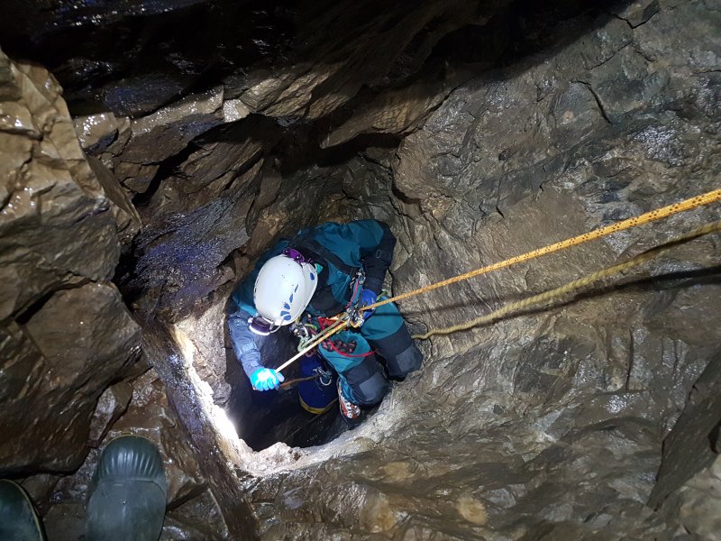
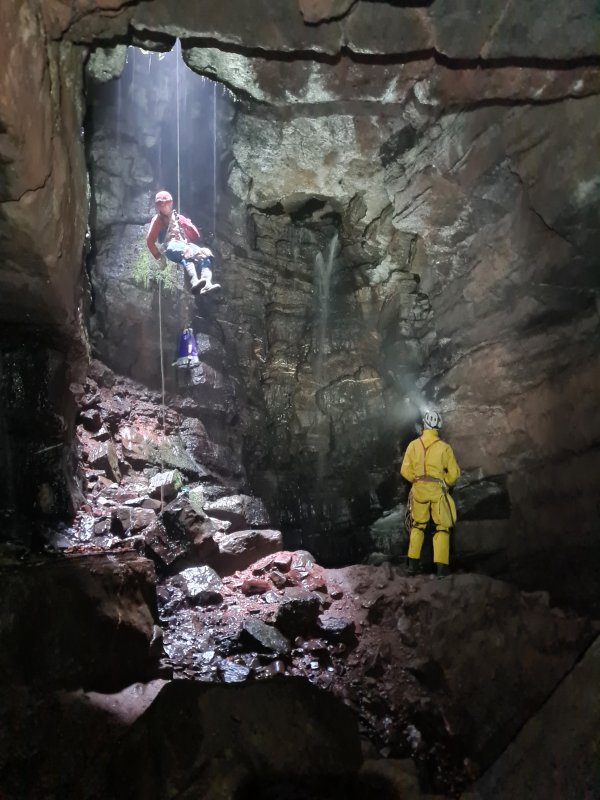
Going down (descending) a rope in a controlled manner, typically using a descender, but can also be done using a body abseil in some cases. Not the same as falling.
This history section is very much abbreviated to show only the origins of abseiling and the terminology, with much more detail provided in the sections on body abseil and descenders. See those sections for more information, including details about how they were first used for vertical caving.
Abseiling has existed in some shape or form for as long as ropes have been used to build buildings, hold the masts of ships, or to dig wells. An early mention is from 1479, when Scottish prince Alexander Stewart slid down a rope made from bedsheets. Sailors from the 1500s to the 1800s slid down ropes which they gripped with their legs, and either slid their hands down, or gripped it one hand at a time. Two descenders are known from the 1500s, with Heinrich Cornelius Agrippa von Nettesheim making one in the Holy Roman Empire (now Germany) from metal in around 1520-1530, and sailors in the Holy Roman Empire (now Italy) experimenting with a simple stick descender in 1549-1550. The same publication described how to descend using doubled rope technique, but it appeared to require gripping the rope one hand at a time, and used counterweights to make it easier, rather than using an abseiling technique. Polymath Galileo Galilei described an early descender in 1638. Improvements were made to it around 1648 by French inventor Nicolas Grollier de Servière (published in 1719), and again in 1725 by German engineer Jacob Leupold, then details were published again in Oekonomische Encyklopädie volume 13 (page 82 and appendix) by Johann Georg Krünitz, in 1778 in Berlin, Prussia, Holy Roman Empire (now Germany). The same publication also described how to slide down a rope using hands instead of a descender, and also described how mountaineers made it easier by using doubled rope technique to reduce the strength needed. In 1787, Genevan mountaineer Horace Bénédict de Saussure used a walking pole as a descender, while descending from Mont Blanc in the French Alps. Many gymnastics books gave details of how to descend ropes safely, as early as 1793. Fire escape descenders started to appear in 1860, initially in the USA, and in many other countries over the next 40 years, so many people had tried abseiling as a result. British mountaineer Edward Whymper used a very basic descending technique that used only his hands during a solo attempt on the Matterhorn in Switzerland in 1862. Though he is actually far from being the inventor of abseiling, French mountaineer Jean-Estéril Charlet-Straton is often mistkenly claimed to have invented it, because he used another very basic descending technique inspired by Edward Whymper's, which also used only his hands (the same way that Johann Georg Krünitz had already described), during an 1876 ascent of Petit Dru in the French Alps. Neither of those were really abseiling, and were both really just ways to use a handline, that sailors had already been doing for centuries. See the sections on body abseil and descenders for more details of the developments in each of them. By 1897, German mountaineers called abseiling "Kletterschluss", meaning "climbing finish". It was first called abseiling in 1930, as the German word for going down a rope. This German name "abseilen" was used in Anwendung des Seiles, published by the Bavarian section of the German Alpine Club in München in that year. The German verb "abseilen" (pronounced "AB-zile-en") literally means "to off rope"; to use a rope to get off a cliff (the word had already been used during the 1600s, but at that time it meant lowering and removing someone from a rope that they had been tied up with, not sliding down it). The French word "rappel" had originally meant to use (in any manner, not just abseiling) a doubled rope, which could then be pulled-through afterwards, or used as a pull-up cord. The word literally means to "recall" or retrieve the rope, and has nothing to do with sliding down it. French mountaineer Roger Frison-Roche is credited with convincing some English speakers to use the word "rappelling" in 1944 (French caver Henry P. Guérin wrote about it using the same word in 1944), and Americans decided to use that word, even though there was already a perfectly good word for it. Both words spread into other languages.
This history section only covers abseiling. This article also has a detailed history of many of the other devices and techniques that are used for vertical caving.
Methods of abseiling that do not use a descender. Instead, the rope is wrapped arount the body in such a way that the body creates enough friction. All of them can leave scars from rope burns. Most of them do not provide a convenient way to rest. All methods are far less safe than using dedicated equipment, and cannot cope with rebelays or deviations.
With the classic abseil (formerly known as the "hot seat"), the rope passes between the legs, under one thigh, over the hip on that side, crossing the chest over to the opposite shoulder, then behind the shoulders, and down the back of the arm, where it is held in the hand. The friction can generate a lot of heat, particularly between the legs, which should not be underestimated when training without wearing an oversuit. Perhaps useful if you like roasted peanuts. This method is sometimes called the Dülfersitz, but this is not actually the method that Hans Dülfer invented. With the shoulder abseil, the rope is held in one hand, passes around the back of both shoulders, then wraps around the other arm if needed to add more friction, and is then held in that hand. The rope may be wrapped around neither or both arms depending on how much friction is needed. They are generally used only on very short, sloping climbs, with the classic abseil being suited to steeper slopes than the shoulder abseil. The classic abseil has traditionally been used for free-hangs. However, in almost all cases, these methods should be avoided, and dedicated equipment should be used instead.
The South African abseil can only be used on a doubled rope, and is virtually never seen in caving, though it is sometimes seen in mountaineering. The two strands run separately under each armpit, crossing over behind the back, passing to the front over the opposite hip, down between the legs, then the two strands pass together underneath one leg, with one hand holding both strands beside that leg. This method is intended to be more stable than most other methods, but is intended for relatively gentle slopes, and can be painful under the arms if used for free-hangs. It is intended to cause less discomfort between the legs, and cause less rope burns than other methods, but simply changes the position of the burns, rather than eliminating them.
Several other body abseil methods were previously in use, but are generally not used any more, often because they are too prone to failure, or cause too much discomfort or serious rope burns. The vast majority need a natural fibre hawser laid rope to generate enough friction, preferably a fairly thick rope or a doubled rope. The gym abseil has the rope held in the hands, then wrapped behind one leg (starting on the outside edge of the thigh), and around the foot, with the other foot trapping it (like the method used to climb a rope in gym classes). To avoid burns, the rope must not be slid through the hands, the hands must take turns to grip while the other is moved a short distance down the rope. This method is quite dangerous and has resulted in several mountaineering deaths, as the rope can slip out between the feet, and the hands then have to do all the work, rapidly resulting in severe burns. It is also painful on the calf that it wraps around. An even less reliable variation of this is to cross the feet over, with the rope running between the thighs, behind one calf, then pinch the rope in the gap between the feet. This method is more prone to the rope slipping out of position, resulting in a loss of grip, but is sometimes taught in gym classes, when using very thick ropes. It is not safe enough to use for abseiling.
The leg wrap has the rope passed between the legs and wrapped once around one thigh, back between the legs, under the same leg, and held in the hand on the same side. The other hand holds the up rope to add a little extra friction. This method squeezes one leg very painfully. The over the shoulder abseil or double leg wrap has the rope passed between the legs and wrapped once around one thigh, then passed beneath the other thigh, and running through a hand up over the opposite shoulder. The other hand holds the up rope. The two leg seat can only be used on a doubled rope. One strand passes beneath each thigh, starting from the outside, then both strands pass up between the legs in front of the up ropes (away from the body), wrap in a full circle around the up ropes, down over the hip on whichever side they started wrapping around the up ropes on, with one hand holding the up ropes and the other holding the down ropes. Essentially, this is an Italian hitch, using your body instead of a carabiner, and is one of the few body abseils to generate friction with something other than your body.
The shoulder wrap (one of the actual Dülfer techniques) passes the rope between the legs, up between the buttocks, up the back, over one shoulder, then held under the armpit of the same arm. The over-the-hip variation has it held in the hand instead of the armpit, crossing over to the other side of the body and lying over the hip on the opposite side from where it passes over the shoulder. The neck wrap (the other actual Dülfer technique) has the rope passing between the legs, over one hip so it returns to the front, crossing over the chest to the opposite shoulder, behind the neck to return to the front, then down under the armpit or into the hand on the same side where it passed over the hip. It is held in the hand only when trying to stop, but normally kept under the armpit to control motion. This method puts a great strain on the neck, and a thick collar is needed to avoid rope burns. If it came down the back of that arm instead of the front, it would have been a classic abseil. The French neck wrap passes the rope between the legs, around one buttock, under the armpit on that side so that it returns to the front, then around behind the neck to return to the front, then held under the armpit or in the hand of the second arm. The Dülfer-Kletterschluß variation is very similar, but the rope runs between the legs at the end, instead of being held by the side. The shoulder wrap, its over-the-hip variation and the neck wrap are not actually safe to use for abseiling, and can only be used on gentle slopes where the feet can make contact with the rock, in order to force the body upright. They were never intended to be used for abseiling, even though they ended up being used for it for many years.
The Dolomite abseil can only be used on a doubled rope. The two strands both run between the legs, then one strand passes beneath each thigh, back over the hips, crossing over the front of the chest to pass over the opposite shoulders, with one hand holding both strands behind the back, and the other hand holding both up rope strands in front of the chest. The Gènevoise method has the rope passing on the outside of the thigh, under the thigh, up between the legs, then over the top of the elbow on the same side, where it is pinched with the elbow. This method actively tries to tip you over, and it would have been better if it passed between the legs, under one thigh, then up over the top of the elbow on the same side. However, that is not how it was drawn or described, and it was described as not being very safe.

The early methods are not known, but presumably, the earliest involved simply holding on to the rope, and sliding down it, which would have been used by sailors, builders and well diggers for almost as long as ropes have existed. In Roman poet Virgil's Aeneid, written in 29-19 BCE, Greek soldiers are described as "having slid by means of a lowered rope" from the Trojan Horse, and while the story is not based in fact, it shows knowledge of how ropes could be used in that way. In 1479, Scottish prince Alexander Stewart slid down a rope made from bedsheets to escape from Edinburgh Castle, but the exact method was not described. Later tellings of the story then included a servant who gets injured, and even later elaborations stated that an actual rope had been lengthened using bedsheets, but none of that is supported by evidence from the time, and the later stories disagree with each other. Sailors from the 1500s to the 1800s are often depicted as sliding their feet down a rope, while using their hands one at a time to grip the rope rather than slide down it, to avoid buring their hands, but it is not known when this practice actually started. A sailor had been depicted holding onto a rope in a similar manner at the end of the 1200s on the Seal of Winchelsea in Britain, and in 1309 on the Seal of the scabini and burgesses of Damme in Flanders (now Belgium), but the drawings are exaggerated and artistic, do not show if the sailors were ascending or descending, and fail to show the ladders that would actually have been there for that purpose (seen in the British Seal Of Dover in 1284). It is more likely to show rope climbing, judging by where the sailors are looking. Quick descent approaches where they would slide the rope through their hands and risk burns were known as "coming down by the run", but it was much more normal to use the hands one at a time, commonly known as hand over hand. In 1613, British playwrights Francis Beaumont and John Fletcher wrote in the fictional work Honest Man's Fortune that sailors would "come down by the rope", after climbing up. In 1556 (but researched from 1528-1550), the book De re metallica (on the nature of metals) listed how metal mining was carried out in the Holy Roman Empire (now Germany, Czech Republic, Austria and Italy) and Hungary (now Slovakia). It described and depicted how miners would sometimes slide down sloping mine shafts "sitting on leather, attached to their waists" at the back and held at the front in one hand, like children sledging in the snow. To control their speed, they would use a body abseil, running the rope under their armpit. This was not a true body abseil, since the majority of the friction came from the sledge, not the rope, and it would never have worked as an actual body abseil.
In 1638, polymath Galileo Galilei described how another young Italian had descended a rope from a window, burning his hands, showing that he had slid down the rope using them. While the specific story about a bedroom window is possibly fictional, the fact that he knew about the problem shows that someone had tried to slide down a rope that way, burning their hands in the process, and that could have been him or someone else. In 1669, British captain Samuel Sturmy and a miner named Dick are likely to have been the first to use any kind of body abseil technique in a cave, in Pen Park Hole, in Bristol. The method is not recorded, but it is likely to have been the one used by sailors. The advice not to slide down ropes using your hands was repeated in France by Gaspard II Grollier de Servière in 1719, and again in 1725 by German engineer Jacob Leupold. In roughly 1763, British navy lieutenant John Hariott "slipped down a rope" in Corsica, presumably using the hand over hand technique.
In 1778, a method to more safely descend a rope by sliding it only through the hands was described by Johann Georg Krünitz in Berlin, Prussia, Holy Roman Empire (now Germany). The suggestion was to cover the hands with gloves or a handkerchief, wetted if possible. A knotted handline was suggested as much better. A mountaineering method was also described, using a rope looped over something solid to add friction or a pulley, such as a hook in a house, sitting on a boatswain's chair made from a wooden stick serving as a sit harness tied to one end, and lowering yourself by holding the other end in your hands, reducing the effort needed by more than half. This is the earliest known mention of descending using doubled rope technique, but it is likely to be far older, possibly used by some sailors or well diggers during previous centuries. Several books about teaching gymnastics described using the less reliable method to trap the rope between the feet while descending with the hand over hand technique, in 1793 and in 1803, and then also with the gym abseil arrangement in 1826, in 1827, and in 1843. All except the first book stated that these techniques originated with sailors. The authors were from Germany, Britain and America, showing that this method is likely to have been used in many countries. French sailors were described as using an unknown approach to slide down a rope in 1797.
Since around 1850, mountaineers had descended ropes hand over hand (with the rope tied using a loop knot around an object such as a rock). Between 1860 and 1864, Algerian well diggers would manually descend and re-ascend ropes into a well. British mountaineer Edward Whymper used a fairly simplistic method of descending a rope during a solo attempt on the Matterhorn in Switzerland in 1862, which consisted of holding the rope with one hand held pointing up the slope, and the other hand loosely holding the rope in front of the body, while facing sideways across the slope, which is basically how a handline might be used (Scrambles Amongst the Alps, Edward Whymper, 1872, page 64). He does not say if he slid the rope through his hands, or used hand over hand. His major innovation was to have invented the modern pull-through. French mountaineer Jean-Estéril Charlet-Straton then used a technique inspired by Edward Whymper's, during an 1876 ascent of Petit Dru in the French Alps. He used a doubled rope (so that it could be pulled down afterwards by pulling on one end), with each end held by an assistant when it was repeated in 1879. Because he could not climb hand over hand using a doubled rope, his method was simply to walk or slide backwards down a very steep slope, with the ropes sliding through his hands which were held out in front of him pointing up the slope; something that could barely be called abseiling, and had no doubt been done countless times before by many people. Sailors and gymnasts had already learned that this approach rapidly leads to friction burns on your hands, and is something that should never be used, unless you are wearing thick gloves. All of the previously mentioned books written up to 83 years beforehand had already warned gymnasts against it, showing how many people must have tried it before Jean-Estéril Charlet-Straton. Johann Georg Krünitz had described the exact same technique as Jean-Estéril Charlet-Straton used, using gloves, 98 years beforehand. Even Galileo Galilei had described the dangers of that approach in 1638, 238 years beforehand. So despite popular opinion, Jean-Estéril Charlet-Straton did not invent abseiling. He did something that was not really any more than using a handline in a way that many people had done before him, and realised was a bad idea. (He also did not invent the idea of retrieving the rope, since Edward Whymper had already done that too.)
In 1878, American firefighter George Reid slid down a hayloft pole to quicky reach a fire engine below, and the concept of the firefighter's pole was created. This is descended in the same way as a body abseil, and although the original method is not recorded, early depictions almost always show the same approach as the less reliable gym abseil method. By 1897, the gym abseil method was used by mountaineers in Germany, optionally wrapping the rope around an arm for extra friction. Originally, it was just called the Kletterschluss, German for "climbing finish", a word that was then used for all rope climbing techniques and body abseil arrangements, and also for belay devices that could be used to make abseiling safer. It later became known as the "Turner-Kletterscluss", meaning "gymnast climbing finish", to differentiate it from the others. If more friction was needed, an unnamed variation described in 1897 by editor Heinrich Hess was to wrap the rope several times around the thigh with the knee held up in front, while sliding the up rope through the hands, and having the down rope go back up through both hands after wrapping around the thigh. He did not suggest whether the rope should start between the thighs, or on the outside of the thigh, but it tries to tip you upside down when it starts on the outside of the thigh, so it would have to be between the thighs. He also suggested wrapping an arm for more friction with the gym abseil variation in the same year. The gym abseil method was recommended in a booklet called Anwendung des Seiles, published by the Bavarian section of the German Alpine Club in München in 1907. It came with the advice to use a lifeline in the top rope arrangement, because of how dangerous it is. This advice persisted in subsequent editions, for all forms of body abseil, until the user of descenders took over, because even the most trustworthy body abseil is still a very risky approach. In 1908, a mountaineer identified as Gsell announced a new abseiling technique in a German newsletter. The technique was probably developed in 1907, and is likely to have been the over the shoulder abseil. The leg wrap was described by German mountaineer G. Hick in 1909, which was very similar to the high friction approach suggested by Heinrich Hess, with the main difference being that the rope was wrapped fewer times around the leg, and the down rope was held to the side, instead of next to the up rope. By 1910, the leg wrap and over the shoulder abseil were appearing together in German and French climbing magazines (such as the 1910 edition of Anwendung des Seiles) in preference to the gym abseil, due to the number of times that mountaineers had died after losing their grip or burning their hands while using the gym abseil method. They were referred to as the "Einschenkelsitz" ("one leg seat") and "Zweischenkelsitz" ("two leg seat") respectively. German mountaineer Hans Dülfer invented the shoulder wrap, its over-the-hip variant and the neck wrap in 1911-1912, to be used for self belaying a traverse, not for abseiling. The down rope was never held in the hand, but the up rope might be held in neither hand, in one hand, or in both hands, depending on which hands were being used to hold the rock, and how steep the slope was. His death in 1915 prevented further development. In spite of him providing content for Anwendung des Seiles, his techniques did not appear in that publication during his lifetime, presumably because he still considered them to be in development.
The two leg seat was depicted in the 1913 edition of Anwendung des Seiles, without giving any details about who invented it, when, or what it was called, but including it under the "two leg seat" heading. In 1922 and 1926, Hans Dülfer's shoulder wrap (referred to as "Schulterumschlingung", a direct translation) was described clearly in Anwendung des Seiles as passing the rope up the back and over one shoulder, which would have run it rather painfully up between the buttocks, making this the earliest known description of the atomic wedgie. The sketch that accompanied the description clearly shows Hans Dülfer, with his distinctive hairstyle. A later painting which appears to be based on the sketches used in the booklet shows the rope running under his collar, and not up his back, and this mistake may have inspired the French neck wrap. The same publication also depicted the neck wrap, referred to as "Nackenumschlingung", a direct translation. At the time, it did not mention that this had been developed by Hans Dülfer, and said it could be used for abseiling, with both hands holding the up rope. The same publication had another sketch of it with the rope hanging down the back, instead of passing around the neck to the front. This seems to be a mistake, as it would not generate enough friction that way, and would probably result in a fall. The publication also stated that the gym abseil was considered very dangerous, and should not be used. In 1923, the Dolomite abseil was described by German mountaineer Verlag Bergland. It had been developed a few years beforehand, used by German mountaineers Georg Weißmann, S. Bergland and their clubs. Ernst Platz depicted the neck wrap being used for abseiling in 1924. To abseil, the climber was shown with their hands on the up rope, instead of holding the rock, or with one hand holding the up rope and one holding the down rope. The Dülfer-Kletterschluß variant was described in German handbook Die Gefahren Der Alpen by Zsigmondy/Paulcke in 1927, attributed to Hans Dülfer, but there is no evidence that he actually developed it.
Italian climber Tita Piaz is credited with adapting Hans Dülfer's technique into the classic abseil, which was better suited to abseiling than traversing. Exactly when this happened is not known, but he was photographed using it (upside down as a stunt) at some point, and the pictures appear to be from the late 1920s, based on their quality, his apparent age and the clothing he typically wore at that time. The modified technique did not appear in German climbing manuals even in 1942, in spite of Tita Piaz having close contact with them. By 1930, Anwendung des Seiles stated that the two leg seat was no longer considered safe. The neck wrap was referred to as the Dülfersitz, again depicted with the down rope being tucked under an armpit, and not held in a hand. While it is not actually known conclusively if he developed it, it seems likely that he did. The Dolomite abseil was referred to in that edition as the braces (suspenders) abseil, with both hands holding the up rope and nothing holding the down rope. Italian publication Lo Scarpone also attributed the neck wrap to Hans Dülfer in 1931. The Dülfer-Kletterschluß is likely to be the second body abseil used in a cave in 1934, by French cavers Henri "Kiki" Brenot and Pierre Chevalier, in the Félix-Trombe cave system in the French Pyrenees. Actual productions of the Indian rope trick from 1935 onwards (as opposed to the legendary versions that never happened) generally show the earliest sailing approach for descending afterwards, but they normally use a pole not a rope.
In 1942, French mountaineer Roger Frison-Roche was photographed using the French neck wrap, which could have been a mistaken confusion between sketches of the shoulder wrap and the neck wrap, or could have been an intentional modification of the Dülfer-Kletterschluß arrangement, since it is basically the same thing, with the down rope on the wrong side of the leg. In that same year, Anwendung des Seiles finally started mentioning that descenders were more reliable than body abseiling, and encouraged their use instead, though it still suggested the neck wrap and Dolomite abseil. In 1943, some cavers in the Mendip region of Britain were using an unknown body abseiling technique, which sounds like the rope was simply wrapped once around the waist and held in one hand on either side, similar to a shoulder abseil, but held too low. It is very similar to (and almost certainly developed from) a body belay, and was used on the sloping piches found in Mendip. The French word "rappel" had originally meant to use (in any manner, not just abseiling) a doubled rope, which could then be pulled-through afterwards, or used as a pull-up cord. The word literally means to "recall" or retrieve the rope, and has nothing to do with sliding down it. Roger Frison-Roche was using a method that he named the "rappel" in 1944 (French caver Henry P. Guérin wrote about it using the same word in 1944), and attributed it to Jean-Estéril Charlet-Straton. The word rappel was misunderstood to mean sliding down a rope, and that mistake stuck, with the American military adopting it in that year, and several countries and languages now use it instead of abseil. However, the photograph from 1942 shows that Roger Frison-Roche was using a variation of Hans Dülfer's technique, not something used in France 68 years earlier. French cavers from the Grenoble region were using the Dülfer-Kletterschluß variation of this in 1944, as well as the Gènevoise method. This method was described in 1944 by Henry P. Guérin.
The classic abseil was already in use by the American military by 1944. Originally called the "body rappel", it was mistakenly called the Dülfersitz, and that name has stuck in some countries. In 1944, the American military used a much less reliable technique, simply passing the rope between the legs and then holding it by the hip with one hand, confusingly called the hasty rappel. They later replaced it with the shoulder abseil. In 1951, American cavers Bob Handley and other cavers from West Virginia, USA, used the classic abseil in caves. American caver William Franklin "Vertical Bill" Cuddington created leather rope guides for parts of the body to avoid rope burns in 1952. Shoulder abseil is used extensively in American military training (called the hasty rappel), and it may have originated there. A rather sloppy version of it was in use before 1969 (seen in "Equal to the Environment"), but without any name. The date of its development is not known, but it is an obvious progression from the approach used in Mendip. The South African Abseil was developed by South African mountaineer Andrew Friedemann in 2000.
This history section only covers body abseiling. This article also has a detailed history of many of the other devices and techniques that are used for vertical caving.
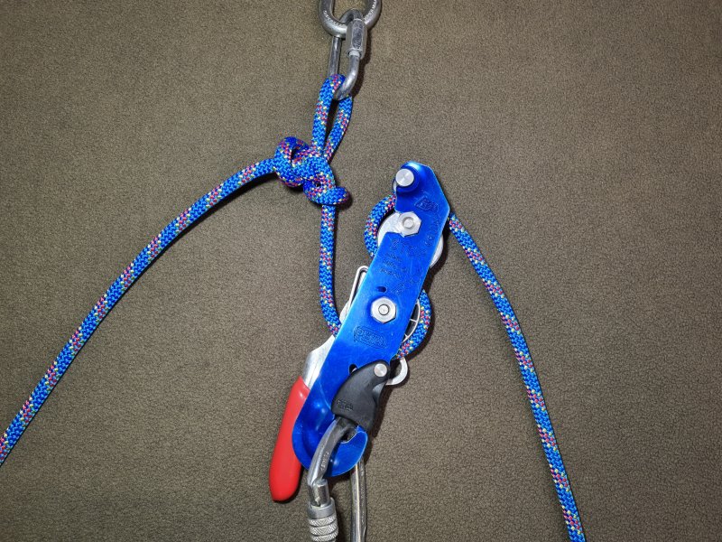
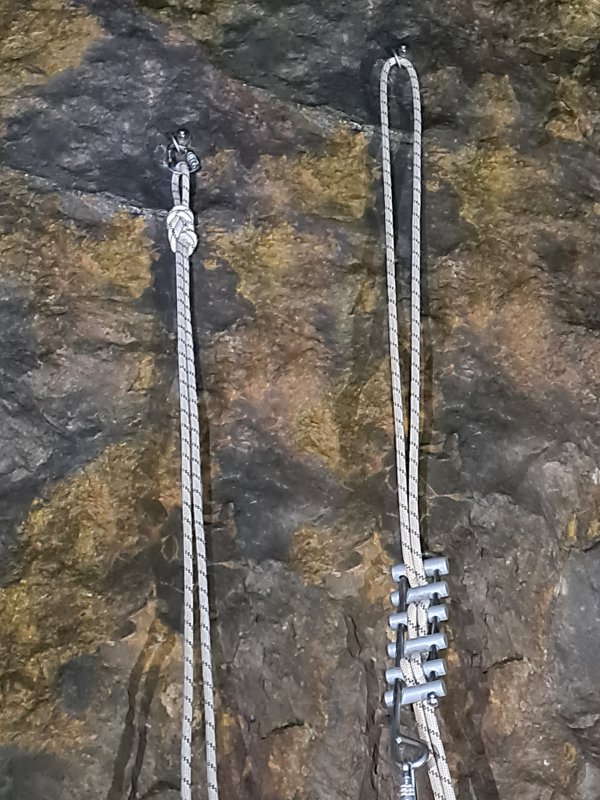
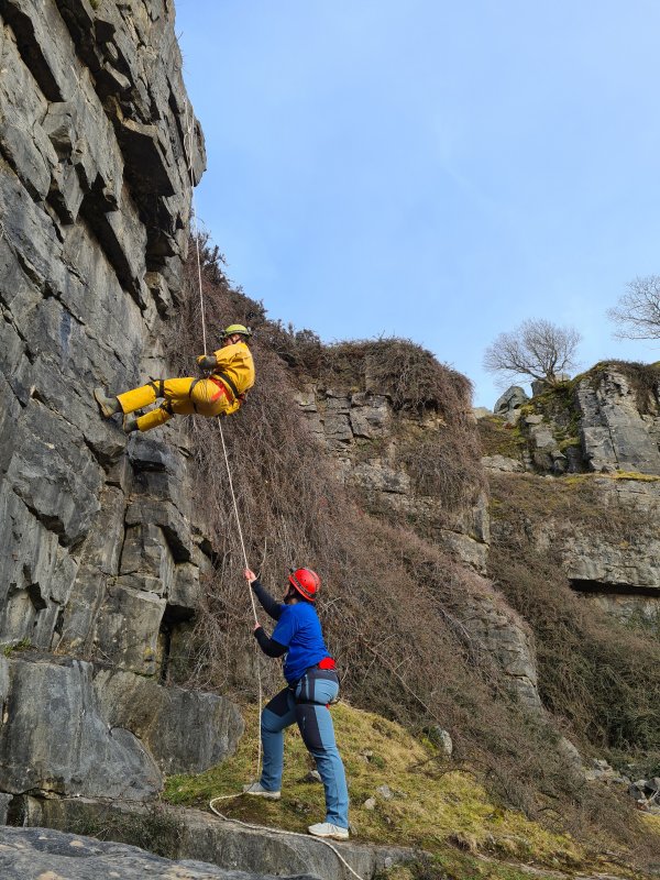
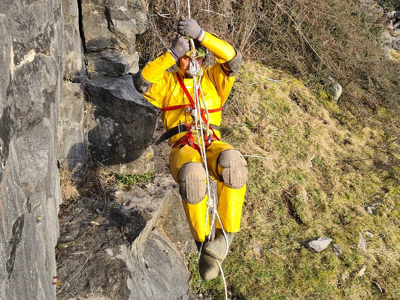
Going up (ascending) a rope using ascenders or friction hitches. There are several prusiking systems, with the main one used in Britain (and in fact most of the world) being the frog system. As a general rule, prusiking relies on having at least two ascenders or friction hitches, and alternating which one is gripping the rope. For it to be considered prusiking, motion should be done using strength rather than using a motor, and one ascender normally holds the weight of the person, while they move a short distance upwards. The one ascender or one knot method would normally be considered prusiking, since the ascender is essential to the process, and it is really just a way to recreate a standard prusiking system without one of its ascenders. Doubled rope technique would not normally be considered prusiking when the rope is manually pulled to ascend, even if an ascender or friction hitch is used to capture progress, as the ascender performs only a secondary function, and motion could continue without it being present.
Originally, ascending a rope consisted of using manual strength to pull yourself up the rope. This was described as early as 170-180 CE by Ancient Greek author Claudius Galen in what is now Turkey, in a health guide intended for the whole Roman empire, De Sanitate Tuenda, book 2, chapter 9. The original Latin text is lost, but a few slightly different transcriptions remain ("Præterasi, quis per funem manibus apprehensum, scandat, sicuti in palæstra pueros exercent, qui eos ad robur preparant." or "Præterea, quis per funem manibus apprehensum, scandat, sicuti in palæstra pueros exercent, qui eos ad robur præparant."). The text translates literally to "moreover, one climbs up, holding a rope in his hands, just as boys are trained in the wrestling gymnasium, which prepares them for strength". It does not mention whether the feet were used. Much later investigations by Johann Christoph Friedrich GutsMuths in 1793, suggest that the rope had been fixed at the top and bottom, and kept fairly tight. Johann Christoph Friedrich GutsMuths wrote that in the Holy Roman Empire in 1793, later Germany, climbing a loose rope might be done with hands only, or by passing the rope between the thighs and trapping it between crossed-over ankles, and also depicted the rope being wrapped several times around a foot instead of trapping it (though this seems impossible to use more than once). When using feet, the rope was grabbed with the hands, the knees were lifted, and the rope was trapped between between the feet or wrapped around a foot. The hands were then moved further up, and the process was repeated. Another common approach mentioned in 1826 is to twist the rope around a foot with the other foot to get more grip. It is not known when each of these approaches developed, but they are all likely to have been developed several centuries earlier at least, and several books since 1803 stated that the approaches of trapping the rope between the feet originated with sailors. To make it easier, the rope could be looped over a higher object, tie yourself to one end and pull the other end, a form of doubled rope technique without any safety. Although it is not known when this technique began to be used, it was described in 1549-1550 by polymath Gerolamo Cardano in the Holy Roman Empire (now Italy), without being related to any specific industry. The traditional Polynesian and Indian methods to climbing trees are very old approaches that are very similar to prusiking, recorded in writing from at least the early 1800s, but almost certainly several centuries older. They tie the feet together in a way that makes them clamp the tree, then grip the tree with their hands. In some variations, they loop a rope around the tree which is held in the hands, sometimes also looping around the body. They then alternate whether they are hanging from the rope loop or hands while moving their feet up, or clamping with their feet and lifting their hands or the rope loop up.
The earliest known use of prusiking was by Heinrich Cornelius Agrippa von Nettesheim in the Holy Roman Empire (now Germany) in about 1520-1530, using ascenders he had developed that worked like a pair of forceps. And no, those dates were not typos, prusiking is extremely old! The exact date is not known precisely, but is presumed to be while he was adding details of how to cast metals to his book series De Occulta Philosophia, and definitely before his death in 1535. The ascenders were intended to be used with the two ascender variation of rope walking, but without being able to slide the ascenders up the rope, so they had to be manually disconnected, moved, and reconnected for each step, which would have been very clumsy. This was described in 1549-1550 by Gerolamo Cardano in the Holy Roman Empire (now Italy), in great detail. The intended purpose of prusiking was not stated, but Heinrich Cornelius Agrippa von Nettesheim had recently finished a career in the Spanish and Holy Roman Empire militaries (1508-1515), and that could well have been an inspiration, though the only reference to it comes from the world of academia, in Latin, not Spanish. He was an academic lecturer from 1509 to 1519 and continued with academic research afterwards in many parts of the Holy Roman Empire, and was established as a polymath, well known for having a great interest in science, mechanics, natural magic, alchemy and philosophy. He is likely to have developed prusiking simply out of curiosity, believing it to have numerous practical uses, all of which would have related to rope access. Knowledge of it, however, seemed to remain entirely within academic circles, and it was not described as being used anywhere.
The next known use of prusiking was by French inventor Nicolas Grollier de Servière, using a clamping jaws ascender that he had developed. The exact date of its use is not recorded, but it was during his retirement which began in 1642 and ended with his death in 1689. It is likely to have been shortly after obtaining the 1647 French translation of a book by Galileo Galilei, which inspired the inventor's research into rope access. The details of his creations were then included in a book by his grandson Gaspard II Grollier de Servière in 1719, along with instructions for its use, which show that it was intended for use with the hands and feet system. The book did not include any information to suggest that Nicolas Grollier de Servière had learned about either ascenders or prusiking systems from anyone else, and it is likely that he had independently redeveloped both of them. The prusiking technique and ascender design were completely different from what Heinrich Cornelius Agrippa von Nettesheim had used, suggesting that there had been no transfer of knowledge between them. There was only a single foot jammer, designed for use with both feet at once, while gripping the rope directly with hands, without any safety measures. Its purpose was to ascend a castle wall during an invasion, or ascend into the window of a tall building.
French roofers and plumbers have been described using a knotted rope to climb buildings from as early as 1684, though the technique is almost certainly much older, as roofers had been described as "dancing on ropes" and "holding firm at places they pass" by René Le Pays in 1664. The technique was described rather poorly in 1723, and described and clearly depicted in two separate publications in 1762. They would stand in footloops which they attached using suspension hooks hooked above the knots of a knotted rope, alternating from one footloop to the other while moving the hooks to the next available knot, and holding on with their hands. This could be used to climb upwards or downwards. It was essentially the same general idea as the two-knot version of the Gérard Alpine technique. This method was described being used by French exterior decorators in the early 1800s, and continued to be described into the 1900s. It was known as "echelle de corde" (rope ladder), "echelle de couvreur" (roofer's ladder) or "corde nouée" (knotted rope), sometimes using the older spellings eschelle or echele.
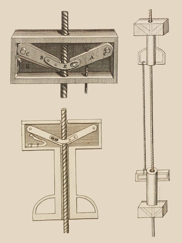
In 1725, German engineer Jacob Leupold from the Holy Roman Empire (now Germany) adapted Nicolas Grollier de Servière's technique, adding a top jammer for the hands, creating the standard hands and feet system, and adding a tether between the ascenders to avoid accidentally dropping the foot jammer. Reverse prusiking required pulling a string or pushing a lever to release the ascender. The spring made bottom weighting difficult, and the suggestion was to hang a rock on the bottom of the rope, but the lever would also have worked. Prusiking was suggested as a way to escape a fire using a rope, by reverse prusiking. He specifically stated that he had learned from the book by Gaspard II Grollier de Servière.
Various hitches were developed, often by sailors, which would have made it possible to save the climbing progress when pulling up manually on a rope, such as the rolling hitch by 1794 and a variation called the Magnus hitch soon afterwards, (both of which were originally used to connect a rope to a spar - a wooden pole), but there is no record of them being used for this purpose until much later. In 1863, Scottish steeplejack and former sailor James Duncan Wright, better known as Steeple Jack, was described climbing a lightning conductor cable to the top of a church steeple, using the same basic approach as the French roofers. He needed to use a lark's foot or a noose as a friction hitch to grip the cable, the same way sailors used to connect things to masts, and at that point, it could be considered prusiking. It was described as being done "by means of loops of spun yarn inserted around the conductor step by step up". It is very likely that he had learned about the footloops from France. Presumably he used the same approach again in 1869 to climb a flagpole, given that he was able to lean on top of it with one foot, suggesting that he had some kind of foot support for the other foot. This technique was used by steeplejacks in the USA by the end of the century, referred to as flagpole stirrups. This method was depicted in an illustration, being used in New York in 1901 to climb a flagpole. In that illustration, an additional loop of rope is passed around the waist and the flagpole, to avoid falling off backwards, since several accidents had occurred that way.
Some time before 1824, French arborists had developed a method to climb trees or poles using metal spikes called "tree climbing spikes" or "spurs" attached to their feet (known at the time as "climbing-spurs" in English, or "griffons" meaning "griffins" or "griffes" meaning "claws" in French). They dug them into the wood, while they would grip the trunk with their hands. Telegraph workers then used the same approach for climbing telegraph poles, but this damaged the wood. This inspired a set of clamping jaws ascenders for wooden poles, which were created by German inventor Ed. von Mengden in 1878. Again, they were intended for use with the hands and feet system, which he had probably learned from one of the books that had discussed it. He then adapted that to prusiking on rope, using the same idea for the ascenders, and created the inchworm system for use with rope in 1879. American inventor William E. Burke reimagined the hands and feet system in 1897, using an ascender for the feet and just gripping the rope with hands, regressing to what Nicolas Grollier de Servière had done 2 centuries earlier. New Zealand inventor Robert Cockerell reinvented the two ascender variation of rope walking in about 1901. American inventor Charles E. Knop also used the hands and feet system in 1902, with an ascender for the feet and nothing for the hands.
In 1905, steeplejacks in New York had developed the Texas system as a safer alternative to what they had previously used to climb flagpoles for painting or servicing, as it held the body upright more reliably if the legs accidentally swung to the other side of the flagpole. They still used a pair of nooses to grip the flagpole, and as a result, they called this approach steeplejack's flagpole slings. One foot was used with a footloop connected to the lower noose, and the other had a loop of canvas around the thigh instead of a sit harness, connected to the upper noose. In 1910, American inventor Iver J. Westad re-described using the hands and feet system with two ascenders on a rope. In 1913, Austrian inventor Johann Machek re-imagined the inchworm system with the body held in a boatswain's chair below the ascender. By 1918 (probably since around 1910), the boatswain's chair was also being used by steeplejacks when using the Texas system, as a better sit harness than the leg loop, and the method was advised to American steeplejacks by the American government.
French caver Léon Pérot developed the frog system in 1920 for use with his prototype ascenders (see that section for more details of the developments there), but did not use them for caving. Antoine Joseph Marius "Paul Cans" Barthelemy developed his own ascenders in 1920 and revealed them at the start of 1921 by ascending to the first platform of the Eiffel Tower in France. They were intended to be used to paint buildings, using rope walking, which he had clearly adapted from the inchworm system used by Austrian Johann Machek and Robert Cockerell's technique. French mountaineer E. Gérard invented the Gérard hitch in 1928, and described how it could be used with the Gérard Alpine technique, which he independently reinvented as a variation of rope walking, for mountaineering. His article was published in 1928 in French publication La Montagne, with more information later in the same year relating to footloops and glacier rescue. It was translated into English in the Alpine Journal in 1929, as part of E. R. Blanchet's article "The Spare Rope In Theory And Practice". The Austrian mountaineering journal Österreichische Alpenzeitung described it in an article by W. F. in December of 1929, and referenced the Alpine Journal translation. Astrian mountaineer Karl Prusik would have read that journal, since he was a prominent member of the Österreichischer Alpenklub that published it (later the vice president of it), and which distributed both La Montagne and the Alpine Journal to its members, and it can be safely concluded that he knew about it. Henri "Kiki" Brenot created the Singes Mécaniques (mechanical monkeys) ascenders in 1929 in the Grenoble region of France, using rope walking, intended for mountaineering. These were the first ascenders and first system used underground, in the Félix-Trombe cave system in the French Pyrenees, along with Pierre Chevalier in 1934.
The classic Prusik knot was supposedly independently reinvented by Austrian mountaineer Karl Prusik in 1931, something sailors were already using (see that section for more details of the developments there). He invented the Jumar system of prusiking, the one knot improvised rescue technique and reinvented the frog system. At the time, he stated that the existing "climbing lock" belay devices, presumably those created in 1904 and 1911, could also be used for prusiking, suggesting that either he had tried to do so earlier during 1931, or that another Austrian mountaineer had tried it, such as Adolf Noßberger, who had told him about them in that year. Karl Prusik did not provide details of whether other mountaineers had tried prusiking with them, or what techniques they might have used. However, he was was almost certainly heavily influenced by E. Gérard's article, though he completely failed to credit anyone, and significant parts of his article could almost be considered plagiarism. At the time, his clubs were openly racist, having been early adopters of what would later become Nazi ideals since 1921 (Karl Prusik himself served as a Nazi captain), and it is extremely likely that they would not have wanted someone from France to get the credit for developing something that they would end up using. According to his climbing partner Wolf Kitterle, he started work on it in the late 1920s, "he guessed 1928", and this is completely consistent with him having learned the technique from E. Gérard.
Mountaineers then conveniently ignored four centuries of prusiking developments in Germany, France, the USA, Sweden, New Zealand, Britain and Austria. They overlooked the fact that mountaineers and cavers (who were also mountaineers) had already been using it with ascenders and friction hitches, and acted like nothing had existed before Karl Prusik, even though they still used the techniques that others had come up with before him. The main reason that his name is associated with prusiking, is that he wrote in German instead of French, and so his article could be read by mountaineers from Austria and Germany. Although cavers had already started to develop their own version of it, mountaineers became the more active users of prusiking for a while, but its use slowly grew within caving. After their use in 1934 by Henri "Kiki" Brenot and Pierre Chevalier in Félix-Trombe, the Singes Mécaniques ascenders started to be used by Pierre Chevalier, Hélène Guillemin and François Guillemin in the Dent de Crolles system near Grenoble in France in 1935. All of them used the ascenders as handholds for a rope climb during the first trip, and during the second trip, Pierre Chevalier prusiked each pitch with them, while the others used a ladder. After that, they were then used mainly as a backup system, with most exploration taking place by using a rope as a pull-up cord for a ladder. If that pull-up cord failed, then they would use the Singes Mécaniques to prusik up the pitch instead, and correct the ladder, so at most, only one person would use them. Most of the time, nobody would use the ascenders at all.
Some time before 1936, American arborists were using the rolling hitch and a variation with an extra turn, which they called a locking hitch, for storing their climbing progress. The rolling hitch also gets called a tautline hitch when it is tied back to its own rope, and American arborist Karl Kuemmerling was apparently using the tautline hitch for this purpose in the 1930s, probably as early as 1932, when he developed a sit harness. This was the first suggestion of prusiking in arboriculture, but ascending still needed them to climb upwards manually using some other method. This idea was brought into British arboriculture in 1936 but most British arborists continued to ignore it, as they preferred to work without ropes. In 1938, Pierre Chevalier used the Gérard Alpine technique with prusik loops made from strands of the main hemp rope to prusik up a pitch in the Dent de Crolles system after a ladder failed to pull up correctly, which is the first known use of them underground. In 1944, American steeplejack Laurie Young described in The Ashley Book of Knots (#454) how steeplejacks from Massachusetts, USA were climbing poles using the Texas system, so it had clearly become common among steeplejacks on the eastern coast of the USA. While this was still used with poles such as flagpoles, the steeplejack's hitch (which the steeplejacks also used by then) would have worked just as well on ropes. In the same publication, a sketch by American sailor Clifford Warren Ashley (#480) shows American arborists looping the rope that they were tied to over a branch, and pulling on the other end in order to ascend, with a variation of the Magnus hitch or a Prusik knot used to save their progress. This is the first time they are conclusively shown using this method, rather than manually climbing the tree. The singe system and two-knot variation of the Gérard Alpine technique were created by cavers in the Grenoble region of France, both described by Henry P. Guérin in 1944, but very poorly in the latter case. They used the Singes Mécaniques ascenders for the singe system, and the Prusik knot for their version of the Gérard Alpine technique. The singe system was probably created by Henry "Kiki" Brenot, and possibly others such as Robert de Joly and Henry P. Guérin.
By 1952, American cavers Bob Handley and Charlie Fort had also used Prusik knots with the Gérard Alpine technique in caves with pitches of up to 30 metres. Other American cavers including Larry Sabatinos, Bob Barnes and Roy Charlton had all used prusiking, but not underground. All had viewed it as something to use in emergencies, not regularly underground. They refused to teach American caver William Franklin "Vertical Bill" Cuddington how to prusik, so he learned their technique from a mountaineering book, and first used it in a cave in 1952. Those techniques may have worked, but they were a significant step backwards compared with what had already been developed in France. However, it is the approach that initially took place in North American caving, and prusiking became synonymous with "climbing on knots". While other American cavers shunned the idea of prusiking, and would use ladders, he started using prusiking heavily in Tennessee in 1953, and started teaching it to friends. His ideas and approaches then spread throughout North America.
Americans started adapting the Gérard Alpine technique into new prusiking systems. In 1955, while creating a method to get over the lip of a pitch, American caver Dan Bloxsom re-invented the frog system as a way to recover from an abseiling emergency, which he called the fourth sling. American caver Huntley Ingalls created the idea behind the Plummer system "years ago" before 1960, probably in 1957. The first commercial mechanical ascender used for caving, the Jümar (later spelled Jumar), was released in 1958 by Adolph Jüsi and Walter Marti, who ran the company Jümar Pangit in Reichenbach, Switzerland. This made SRT more accessible, and within a few years, cavers around the world started experimenting with it more heavily. The Jumar system was recommended for use with them. British cavers, specifically those from the South Wales Caving Club, are first known to have used prusiking in 1958 after being sent instructions for the Gérard Alpine technique by American cavers. The Texas system was independently redeveloped by cavers from Austin, Texas, USA, in 1960. Cavers from the South Wales Caving Club, including John Victor Osborne, reinvented the hands and feet system in 1963-1964, as a way to prusik up the cables if a winch failed, using mechanical ascenders that they based on commercial cable clamps. They probably never used it underground. Jumars were used in a cave for probably the first time in the early 1960s, in Biolet Cave in the Grenoble region of France, but it was about 1965 before they were used for caving in the USA. Despite the Jumar system being originally created for use with prusik loops, cavers initially seemed to almost completely separate the two systems; if using Jumars, cavers used the Jumar system in North America or Europe, or rope walking or the singe system in parts of France. If they used prusik loops, they used the Gérard Alpine technique or Texas system in the USA and Britain, or the two-knot variation of the Gérard Alpine technique in France. American caver Bill Plummer developed the Plummer system between 1960 and 1966, and it was initially used exclusively for prusik loops.
Inspired by the Gérard Alpine technique, Americans Robert E. Henshaw and David F. Morehouse (presumably cavers) recreated rope walking for their Climbing Cam mechanical ascenders in 1965, which became known as cams on feet, since each foot had an ascender strapped directly to it. An unknown American caver recreated the singe system some time around 1965 for prusik loops. Even after American cavers started using them in 1965, many cavers in America initially shunned mechanical ascenders, assuming they would cut through ropes, and mechanical failures could not be dealt with. Some said that it was safer to teach new cavers to use prusik loops, so that they could recover after an ascender inevitably fails, since they might stop working or break at any moment due to the relatively low quality aluminium manifacturing methods compared with modern ascenders. That attitude persisted well into the 1970s, and while the mechanical ascenders that American cavers used in the 1960s were a little unreliable, the use of prusik loops had in fact been responsible for several serious incidents, because of the natural instinct to grip them when something goes wrong, which causes them to disengage. They are also very difficult to get over a lip, and incidents often happened there. At least one fatal incident happened at the Devil's Sink Hole in the USA, when prusik loops came untied from a caver. These incidents contined, and in 1985 in Fourth Of July Cave, Alabama, a caver using the Gérard Alpine technique had their chest prusik loop break, resulting in them falling upside down without a safety cord or chicken loops to catch them, and had caught themselves upside down using their toes in their footloops, which fortunately were tight enough for them not to slip off. This was most definitely luck rather than clever design, and by 1985, there was plenty of knowledge about safety measures that could have been used. They had to wait, hanging upside down, while somebody else gently reverse prusiked down to them, and connected them to a proper ascender. They were extremely lucky to have survived.
1966 was a busy year! The Wisconsin system was created for Jumars independently by American cavers Dick Boyd, Carl Poster and Bob Olmstead from the University of Wisconsin in 1965-1966, which was incredibly close to being the frog system. At the same time, they stated that people were occasionally using mechanical ascenders with the Plummer system and Texas system. American Charley Townsend re-invented the inchworm system in 1965-1966, as an ascending method for Jumars, after a mishap during the 1965 American National Speleological Convention. William Franklin "Vertical Bill" Cuddington created the Kaczmarek version of the Plummer system in 1966, still aimed at prusik loops. Rope walking was adapted again for mechanical ascenders from the Gérard Alpine technique in America by caver Charles Gibbs and Cleveland Grotto members including Warwick Doll and Lee Watson, some time around 1966. They created the precursor to the three Gibbs ropewalker arrangement, with the knee jammer strapped to the knee, and a prusik loop tied to a very basic chest harness instead of the shoulder jammer. The frog system was redeveloped between 1966 and 1968 by French caver André "Ded" Meozzi, in the Grenoble region of France.
During the exploration of Sótano de las Golondrinas in 1967, cavers used either prusik loops, or Jumars with various prusiking systems that would normally have been used with prusik loops. One caver was told not to use a club-made copy of a Jumar, as it was deemed to be sharp enough to damage the rope. The Mitchell system was invented by Richard "Dick" L. Mitchell in the USA in 1967, and very quickly became the dominant system in southeastern USA, winning over some prusik loop users including William Franklin "Vertical Bill" Cuddington. Mike Kaczmarek separately recreated the Kaczmarek system variation of the Plummer system in 1967. Unknown American cavers recreated the singe system from the inchworm system, and called it the number one Texas system, some time between 1967 and 1972. In 1967, American cavers held the first rope climbing contest at the National Speleological Society Convention, which is responsible for many of the efficiency improvements that subsequently happened with prusiking. Over the years, it also started to draw increasing criticism for how it encouraged cavers to build impractical or downright dangerous configurations, where safety features and functionality were sacrificed for speed, so that a single piece of equipment failure might result in death, and prusiking rigs might not allow cavers to cope with obstacles, leaving them in need of improvised rescue. For some competitors, this became the sport, racing up pitches, rather than actually going caving to see the cave. Also in 1967, British and Canadian students explored Sótano del Río Iglesia in Mexico, and seem to have used rope walking.
The spiderweb system variation of the Plummer system was created by an unknown American caver somewhere between 1968 and 1972. The chest roller was added to the Mitchell system in 1969 by American Keith wilson. William Franklin "Vertical Bill" Cuddington briefly used the ropewalker configuration around 1969, while it still used a prusik loop tied to the chest harness. During 1969, the ropewalker configuration changed to replace the prusik loop with a third Gibbs ascender, at which point it was called the three Gibbs ropewalker. William Franklin "Vertical Bill" Cuddington developed and taught the three phase system variation of the Mitchell system between 1969 and 1974, making it more common to use mechanical ascenders with the Plummer system and Texas system. The Jumar system was poorly depicted in the British Descent magazine issue 10 in 1970, without showing that a chest harness was needed. The idea of a floating cam was developed by Kirk MacGregor in Toronto, Canada some time around 1970 (it set a speed record at the start of 1971), using surgical tubing instead of bungee cord to pull a knee jammer upwards. This revolutionised rope walking. Between 1971 and 1974, he added a chest roller to rope walking, adding a further speed boost. This configuration would go on to be the most popular, and rope walking started to dominate the other prusiking systems in America. This configuration would become known as the Howie rig in Britain. In 1971, American caver Richard Weisbrod turned the inchworm system into a very clumsy frog system without a footloop. Prusiking played a crucial role during the British expedition to Ghar Parau in Iran in 1971, using Jumars with the Jumar system (then considered the normal method of prusiking in Britain), Jumars or Clogs with the Texas system, or Gibbs ascenders with the three Gibbs variation of rope walking. During the 1971-1972 preparation for the 1972 return expedition, cavers also reinvented the frog system, seemingly without realising that it existed in France already, and it was the most commonly used system on the expedition. Peter Standing wrote about it, and John Allonby was one of the ones using it, while Glyn Edwards may have helped develop it.
The frog system started being taught to cavers in other regions of France starting from 1972, and rapidly spread to other countries. Some time around 1973, an incredibly silly variation of the singe system was created from the inchworm system, which used a rocking motion to gain a little extra height. At the same time, someone else recreated the Kaczmarek variation of the Plummer system. The pygmy system was created by American Vern Smith in 1974, as an adaptation of the Mitchell system that ended up being identical to the Gérard Alpine technique, for mechanical ascenders. Prusiking finally became the dominant approach for ascending pitches in Britain, with the major change starting since 1974. The Italian technique was developed in Italy in 1974. In 1975, Petzl's Jean-Louis Rocourt suggested making a dedicated chest ascender based on Bruno Dressler's earlier design, allowing the frog system to rapidly become dominant across Europe, from where it spread to the rest of the world. The main reason for its dominance is that it can cope with Alpine rigging that was being developed at that time, as well as most other obstacles. It also relied on minimal equipment, that could be put on and taken off quickly for caves with awkward passages between pitches.
"Some years" before 1979, presumably around 1976, American caver David R. McClurg had started using a prusik loop as a quick attachment safety with the three Gibbs variation of rope walking. The another prusiking system was developed and named by British caver Mike Cowlishaw, combining the Mitchell system and the static knee jammer from the three Gibbs ropewalker variation of rope walking, in 1976, with details published in 1977. The Gossett system variation of the Jumar system was created by American Jim Gossett in 1977. The floating cam approach was then combined with the Mitchell system, described by British caver Nick Thorne in 1978. In 1978, American Gary D. Storrick described a four Gibbs system, adding a handheld ascender to a Howie rig, and making the floating cam optional. The Ded-Mao-pompe variation of the Italian technique was first described by French cavers Bruno Dressler and Pierre Minvielle in 1979. In 1979 Ron Simmons added a mechanical quick attachment safety to the rope walking system. The Murphy system variation of rope walking was used by Russian cavers from Pluton Caving Club some time before 1981, as a method to climb cables, with the quick attachment safety connected to a backup rope.
Rope walking developed into the common double bungee configuration in 1981, announced by American Kathy Williams. A foot jammer was suggested for the frog system by John Forder in 1982, using the floating cam approach from rope walking. The singe system was recreated by Bruce W. Smith in 1983 as the portly prusik. By 1987, the double bungee variation of rope walking used a pulley, producing the most popular and most efficient version of it, which remains dominant in some parts of the USA. The Murphy system was recreated by American William Shrewsbury in 1987. In 1989, American Bill Farr independently recreated the another prusiking system and called it the rope hopper. The dedicated foot jammer for use with the frog system appeared in 1990, with the French Millet 9400 Aphanicé-Boulourd. The frog system spread to North America, and started to take over from the other systems during the early 1990s, but there are still significant parts where rope walking or the three phase system variation of the Mitchell system are dominant. Actual prusiking finally started to appear in arboriculture after 1990. During 1991 and 1992, the RAD system variation of the frog system was developed by Canadians Robert Chisnall and Michel Goulet, for use by rescue services, when trying to adjust position relative to a stretcher. By 1992, American arborist Michael David Gardner of Rope Step Inc. had reinvented the hands and feet system, using a fabric mar-bar for the feet. The stair climbing method, a conversion between the frog system and rope walking, was originally described by Georges Marbach and Bernard Tourte in Alpine Caving Techniques, 2000. By 2007, the Mitchell system with floating cam had merged into the another prusiking system.
This history section only covers prusiking. This article also has a detailed history of many of the other devices and techniques that are used for vertical caving.
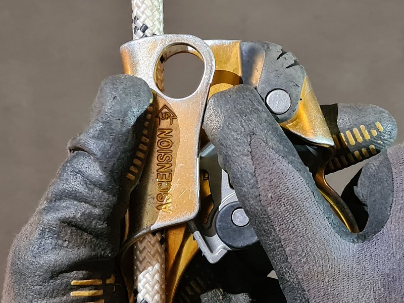
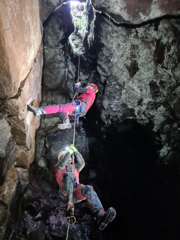
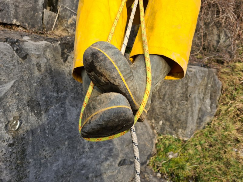
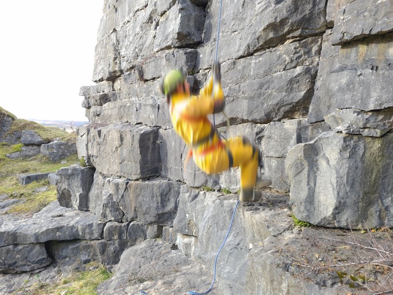
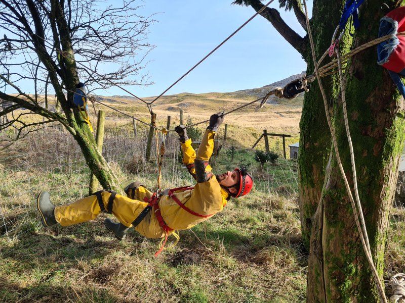
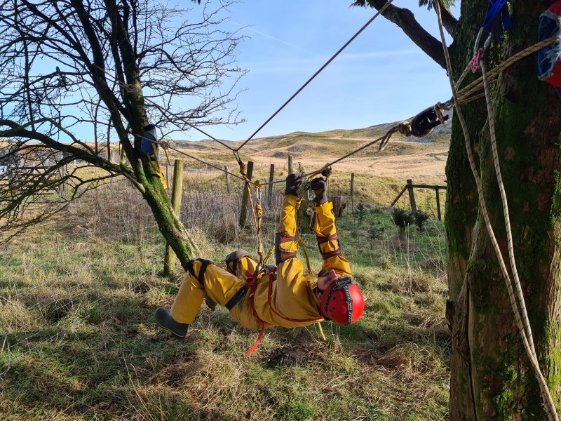
A traverse over a long distance with anchors only at each end, not in between, and no ledge to stand on. Crossing it involves clipping a cows tail to the rope, or a pulley on the rope, and pulling yourself along the rope. The rope needs to be kept under fairly high tension, to prevent it from sagging too much, as progressing uphill is very demanding, and this can cause extreme stress (several tonnes) on the rope, depending on how much sag is allowed, and the length of the Tyrolean traverse. The rope is usually tensioned using a Z-rig. A Tyrolean traverse may use two separate ropes, a tight one to connect a cows tail or pulley to, and a loose one to prusik along, in order to make progress. The loose one also acts as a safety line in case the tighter line snaps from the stress (a serious consideration). Cows tail carabiners can sustain significant damage from the abrasion while crossing a Tyrolean traverse, so a pulley is suggested. Tyroleans should be avoided in almost all cases, and should ideally only be used with steel cables or Dyneema. Unless there is a specific hazard (such as fast flowing water) that needs to be avoided, one alternative is to have a long loop, so that you have to abseil down one side, then perform a mid-rope changeover, and prusik up the other side. A tension traverse is an adaptation of a Tyrolean traverse that is less stressful on the equipment.
It is tempting to think of a Tyrolean traverse as a zip line, also known as a death slide, where it can be at a perfect angle to allow gravity to pull cavers across at high speed. However, a Tyrolean traverse does not have any braking system to slow them down at the far side, so it really might turn into a death slide. Such a steep angle also would largely prevent a return across the Tyrolean traverse, except by prusiking at a very awkward angle. A Tyrolean traverse is not a zip line. It is also not a slackline, highline or tightrope.
In rare cases, a Tyrolean traverse might also have a foot rope which is also tensioned, so that the lower one can be walked over while the upper one is used like a normal Tyrolean traverse. This is more common with commercial adventure courses, where it is commonly called a postman's bridge, two-rope bridge or double rope bridge, but all of these terms will get you funny looks with caving.
In British English, it is normal to call it a TIH-ruh-LEE-un truh-VERSE (emphasised syllables in upper case). However, language is a fluid thing, and there are numerous incompatible pronunciations used globally, with Australians and some Americans typically calling it a TIE-ROLL-ee-an TRA-verse. Many Americans and some British cavers or climbers use British pronunciation for Tyrolean, but use TRA-verse instead of truh-VERSE.
However, it is important to note that Tyrol is an actual place in Austria and Italy, and in both German and Italian, they pronounce the name teer-OHLL. The pronunciation TIE used in Australia is absolutely incorrect, resulting from reading it in the wrong language. The name likely originates in Celtic (where it was spelled differently), where it would would have been pronounced far closer to the German and Italian pronunciation. The common British pronunciation is much closer to being correct, but the wrong syllable is emphasised. So we are all wrong in English, but the Australians are far more wrong than everyone else.
The maximum force on the anchors at the ends of the Tyrolean traverse (or a slackline or tightrope) can be approximated as:
load on the Tyrolean × length of Tyrolean / ( 4 × sag )
or calculated accurately as:
0.5 × load on the Tyrolean / sin( angle of the sag below its normal )
where:
angle of the sag below its normal = tan-1( 2 × sag height / length of Tyrolean )
so:
0.5 × load on the Tyrolean / sin( tan-1( 2 × sag height / length of Tyrolean ) )
However, it is worth noting that the force changes as a person crosses the Tyrolean traverse. The maximum force is experienced when the person is in the middle. The force when they are near one of the ends is significantly lower, perhaps just two thirds of what it is when they are in the middle. With a Tyrolean traverse whose ends are at the same height, the anchor that they are closer to sees a slightly higher force than the other anchor. With a significantly sloping Tyrolean traverse, the force on the upper anchor is always higher than on the lower anchor, and the force on the upper anchor is slightly higher when the person is at the lower end rather than at the upper end, while the lower anchor sees the same pattern as normal. As a result, the sag needs to be measured when the person is in the middle of the Tyrolean traverse. The forces can double if the person crossing the Tyrolean traverse bounces around, and this effect increases further with non-stretchy materials. After it has been used once or twice, the rope normally relaxes to a slightly longer length, and will need to be re-tensioned again to get back to the desired tension. Once the tension is removed, the rope will then relax slowly back to its original length. To give a general idea of the numbers, with slacklines and highlines (which you might see people walking across above gorges), tensioning is normally kept to between 200 and 400 kg without anyone on the line, and the forces under load are normally kept to under 700 kg even if someone bounces around or falls on it using their safety line (a similar idea to a cows tail). However, in extreme cases, the tensioning forces might be 700 kg at each end, 800 kg when loaded, and a person bouncing around could add another couple of hundred. Common safety advice is that the highest forces should be kept to a fifth of the minimum breaking strength of the anchors, knotted rope and other equipment. If you cannot work through all of that to determine if you are able to safely rig a Tyrolean traverse with the equipment you have, then do not rig a Tyrolean traverse.
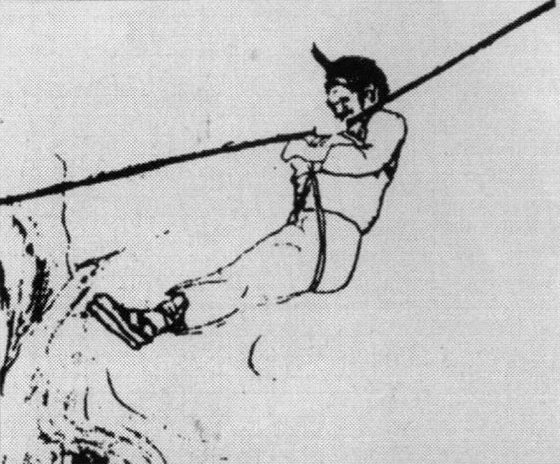
Aerial ropeway transportation systems first appeared in 250 BCE in southern China, and were used as a way for people and goods to cross rivers or gorges. The earliest known one was used exactly like a modern Tyrolean traverse, with a static rope, and a person hanging from it using a sit harness. Aerial ropeways then spread throughout the world, and were being used in Japan by the 1300s, and Europe by 1411, with Johannes Hartlieb depicting one in the Holy Roman Empire (now Germany). In some versions, the ropes would be moved, while in others the ropes stay still, and another rope is used to pull a person or goods across the traverse. German Paul Stephan described in 1926 how a similar rope transport system of some kind existed between 1536 and the 1890s between Santanda and Merida in South America (sometimes mistakenly quoted as South Africa), but without citing any evidence. It was installed by the Spanish explorers, and was probably between the Santander region of Colombia and the Mérida region of Venezuela, which at the time straddled the modern border of those countries. Croatian Fausto Veranzio designed a ropeway in 1616 (which later developed into aerial ropeways for mining and cable cars).
A 1795 engraving of fowling in the Orkney Islands showed a person sitting in a basket on top of a Tyrolean traverse. In 1837, French explorer Stanislas Marie César Famin described and depicted Colombian Tyrolean traverses known as "tarabite", which were used by the Colombians to cross rivers if a more substantial bridge was not available. They would hang from a hook on the rope, and would either be pulled across with a second rope, or would pull themselves along the rope, exactly like a modern Tyrolean traverse. The modern Tyrolean traverse is said to have been developed by climbers in the Tyrolean Alps in Austria and Italy in the late 1800s and early 1900s, but it is essentially no different from what was already used in China 2150 years before, and Colombia 65 years before. The earliest known mention of their use is when Austrian climber Antonio "Deo" Dimai used a Tyrolean traverse on Torre del Diavolo in 1902, in the Cadini di Misurina mountains of Italy, along with Hungarian companions Baroness Ilona von Eötvös and Baroness Rolanda von Eötvös. It is perhaps interesting to note that while Antonio "Deo" Dimai was from the historical Tyrolean area in what was then the Austrian Empire, now Italy, the actual Tyrolean traverse was done between rock pinnacles that are just outside that region in Cadore, Italy, so perhaps it should be called a nearly-Tyrolean traverse or Cadore traverse.
In 1912, 15 year old French caver Norbert Casteret rigged what he described as a Tyrolean traverse over a pitch, made from a tree which he had cut down and dragged a very long way into the Gouffre de Planque. Rather than walking over it as a bridge, he assumed it was not strong enough to take his weight, so to make himself magically lighter, he swung underneath it from his hands, to cross the pitch. This is the first known example of someone using monkey bars underground. From 1921 onwards, a rudimentary Tyrolean traverse was used at the Double pots in Swildon's Hole in Britain, to allow most members of the team to avoid the pools. The rope was hung from using only the hands, not a cows tail, and it sloped quite steeply over the pools, attached to solid naturals at each end. This was documented by Herbert Ernest Balch, without stating who had actually used it first, but it was 15 members of the Wells Natural History and Archaeological Society, including Herbert Ernest Balch, Reginald D. R. Troup, Ernest E. Barnes, and J. Harry Savory. Mountaineers are depicted using a relatively simplistic Tyrolean traverse in 1922, in Anwendung des Seiles, published by the Bavarian section of the German Alpine Club in München. One end was fixed, while the other was tensioned by a person putting their weight onto the end of the rope after passing it through a carabiner. This would not have worked well, and was quite risky, so the person crossing the Tyrolean traverse needed a belayer at each end. Mountaineers were then depicted using a more normal Tyrolean traverse in 1930 in Anwendung des Seiles, using a method very similar to cavers, with a cows tail made from a lifeline and carabiner.
In 1937, the Wessex Cave Club installed what was called a ropeway or cable-way for visiting cavers to use in the British Lamb Leer Cavern, using a design which was clearly based on the ones used for mining. It used a tensioned cable over 20 metres long, attached to scaffolding on either side of the chamber, at 21 metres above the steeply sloping floor at its higher end, sloping gently to only just above the floor at its lower end, where the floor had ramped up to meet it. A carriage made from a wooden box with a metal frame was hung from a pulley which ran along the cable, in a very similar way to a mining kibble, with one person sitting in the carriage. The carriage was pulled or slowly released to run along the cable using a winch which was installed at the upper end. The winch rope continued to the other end of the cable, looped back through a pulley, and returned to the other side of the winch, so it could be used to pull in both directions if needed, though gravity meant that this feature was not actually needed on the sloping cable. Apart from the winch, this uses exactly the same principle as a tyrolean traverse, though it is clearly far more engineered than most other designs. This was all done in the age of candles, when caving gear consisted of a smart suit, a helmet only if you were lucky, and maybe even a fancy bonnet for women. It was planned and generally designed by Austin Wadsworth of the Wessex Cave Club starting in 1936, with the winching system and some other components designed by Mr. Evans, a local lift manufacturer. It is not known when cavers first used the more normal Tyrolean traverses. However, in 1941, French cavers Pierre Chevalier, Fernand Petzl and François Guillemin explored a passage in the Dent de Crolles system near Grenoble, and named it Galerie de la Tyrolienne, with a Tyrolean crossing shown on it (in Subterranean Climbers, 1951). They did not explicitly state if a Tyrolean traverse was actually used there, but it is extremely likely, given the name. Tyrolean traverses are depicted as being used by cavers in the Grenoble region of France, in Henry P. Guérin's 1944 book "Spéléologie, manuel technique; Le matériel et son emploi Les explorations".
This history section only covers Tyrolean traverses. This article also has a detailed history of many of the other devices and techniques that are used for vertical caving.
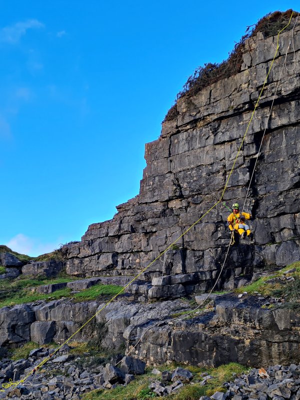
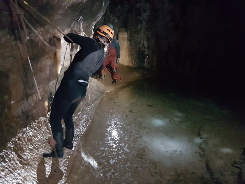
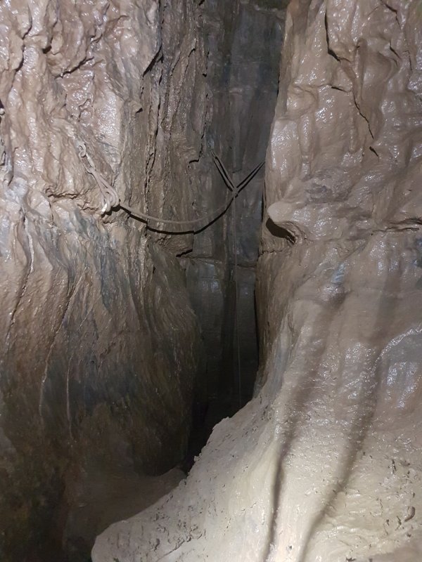
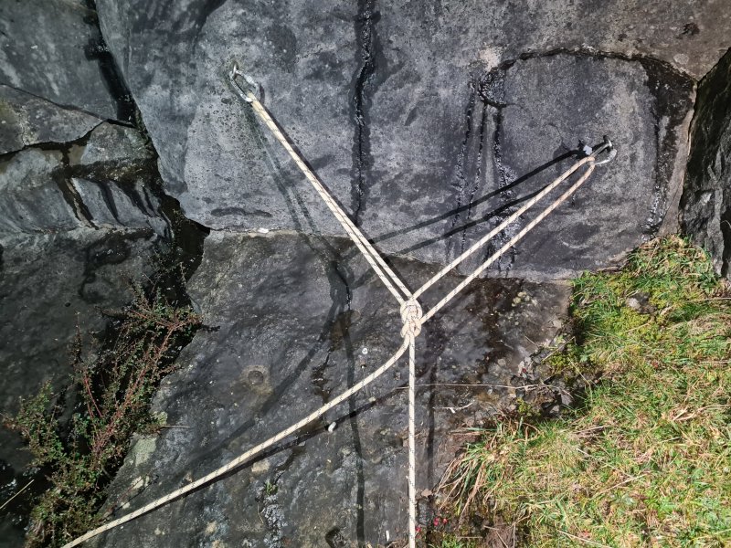
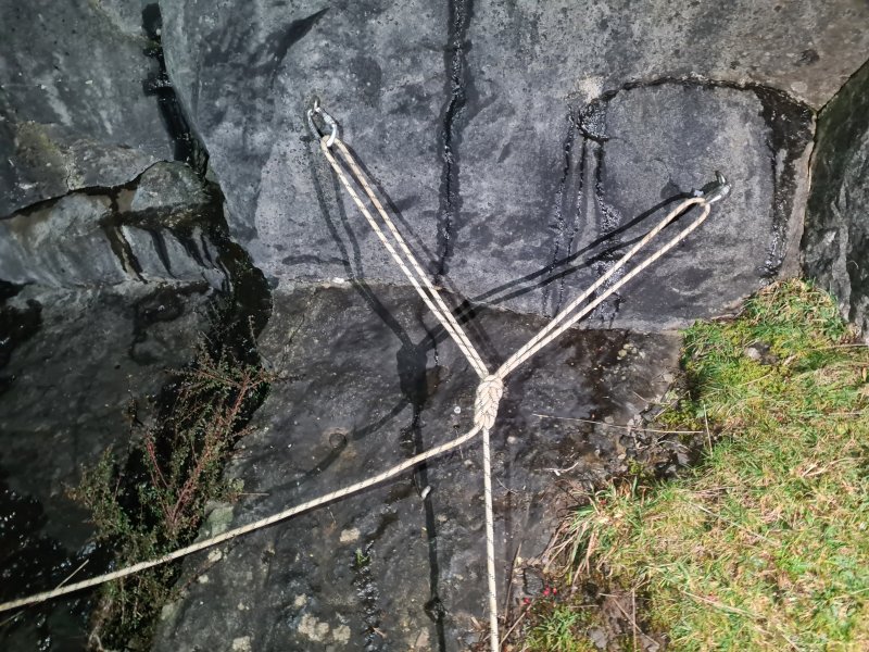
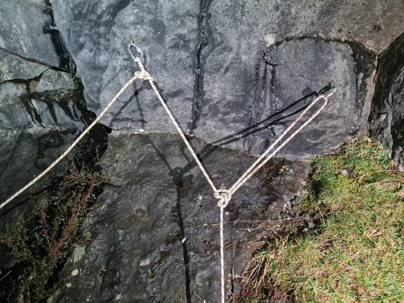
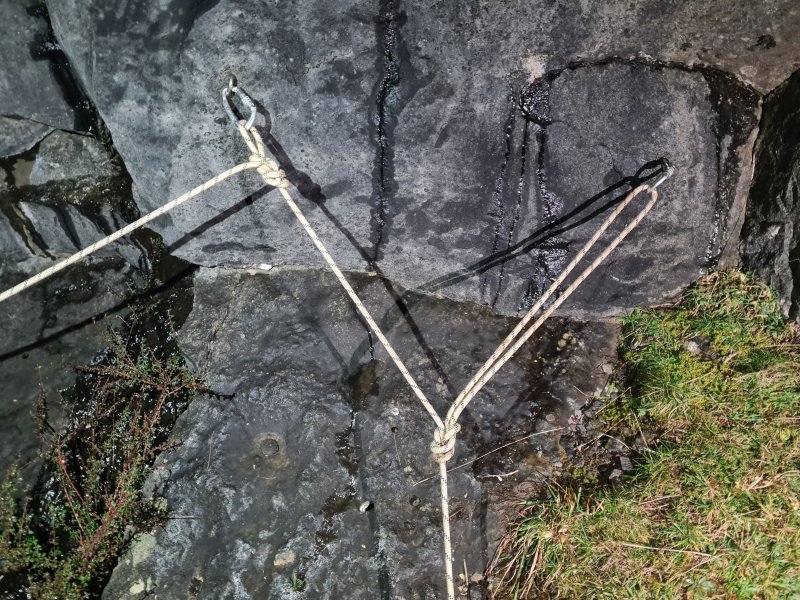
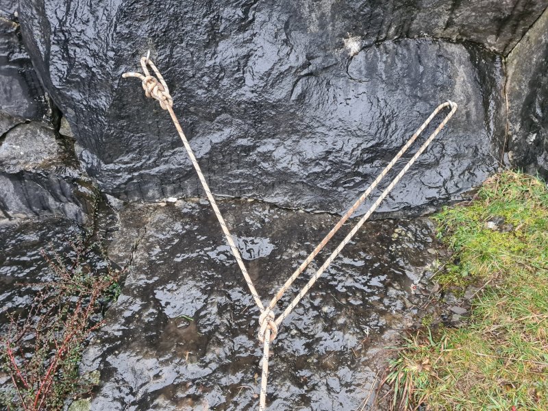
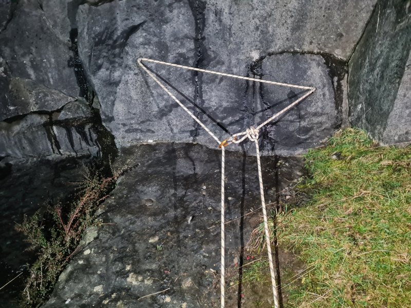
A double attachment point, usually used at the top of a pitch, to share the load of the rope and caver, between two attachments instead of one. Provides redundancy, so that if one fails, there is a second one to take over. Allows fine control over where the rope hangs between two walls of a pitch. This is useful for avoiding rub points, or to avoid the knots rubbing against the rock. As long as the angle of the Y-hang (between the arms of the Y) has been set up to be less than 90°, which it is supposed to be, each attachment point sees less than the full load. On average, they will each see more than half of the load. At a perfectly balanced Y-hang with an angle of 90°, each attachment point would see 71% of the load, pulling towards the knot. At an angle of 120°, each attachment point will see the full load, removing one of the benefits of using a Y-hang. At angles greater than 120°, each attachment point sees more than the full load. This effect is particularly noticeable with the Y-hang used for a pull-through.
Assuming an equally balanced Y-hang, the force on the anchors of a Y-hang can be calculated with the same formula as a Tyrolean traverse:
0.5 × load on the rope / sin( angle of the arm from horizontal )
where:
angle of the arm from horizontal = 90 - ( angle between the arms / 2 )
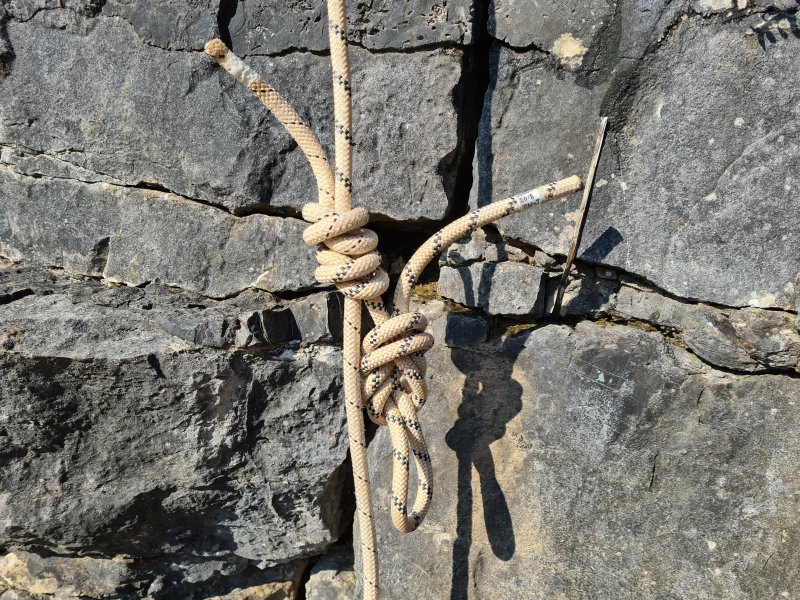
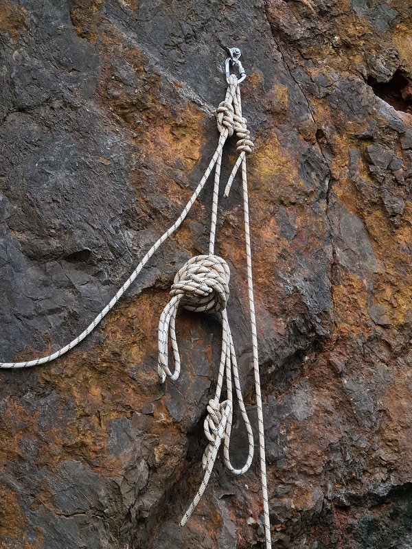
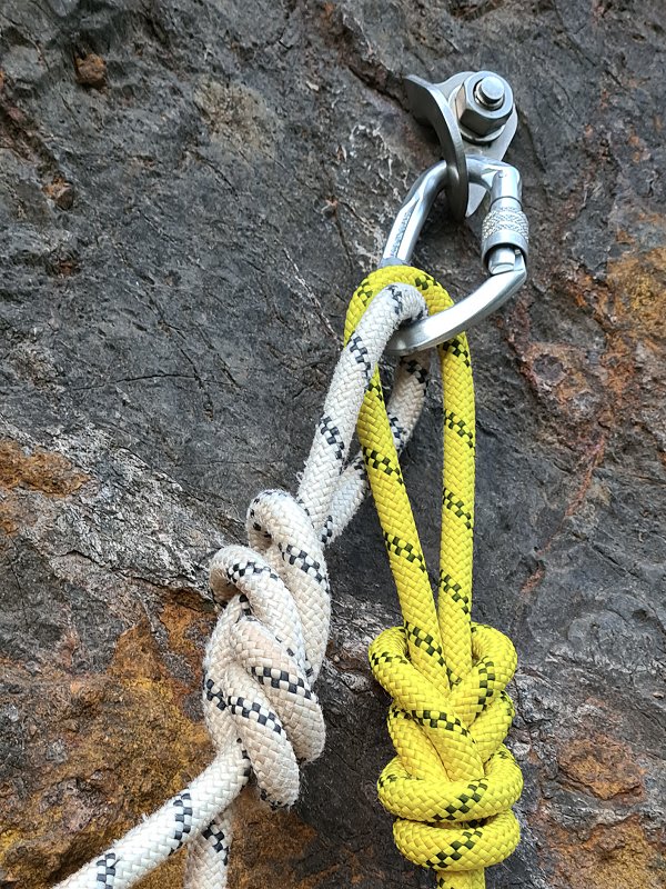
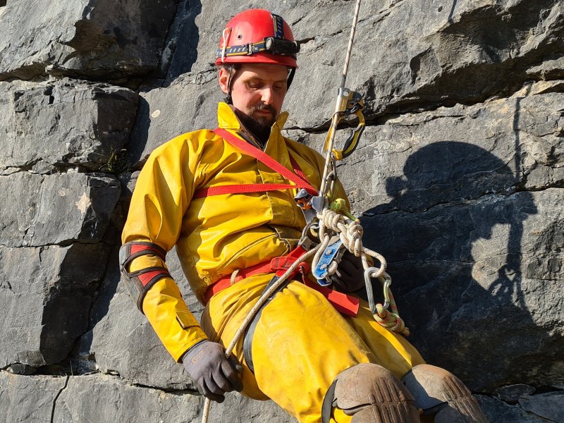
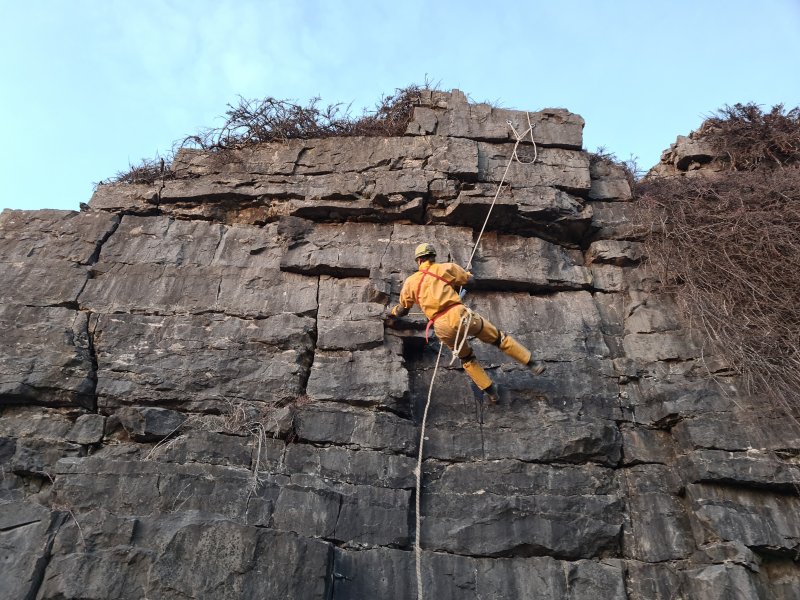
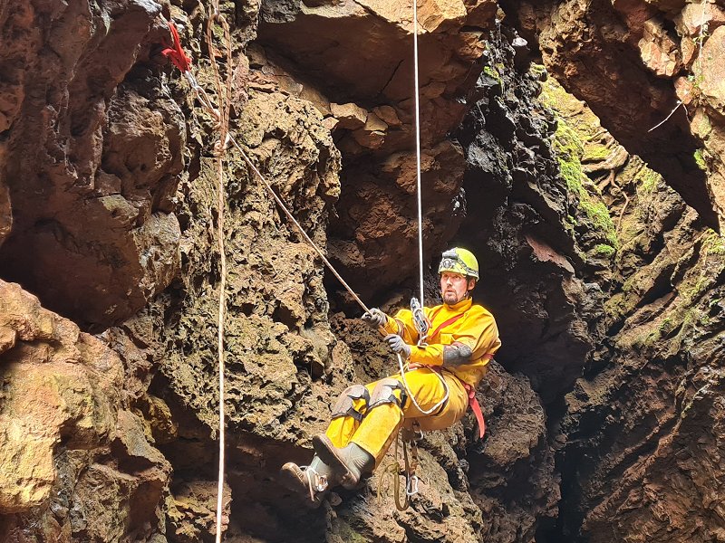
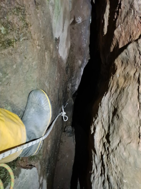
A knot tied roughly 2 metres before the end of a rope when it is packed (or at some point before being rigged), so that you cannot abseil off the end if the rope turns out to be too short, because the knot jams into the descender. You will have some spare rope to use for making helpful loops when that happens, so that there is something to clip into, or to use as a foot support. The most common knot for this purpose is a figure of 8, but a bulky loop knot or other bulky knot like a multiple overhand knot can also be used. Known as a "stopper knot" outside of the caving world, but that confuses it with the stopper knot used by cavers.
The term "idiot knot" does not refer to it being something only an idiot would use. Instead it refers to it being used to save a life in case someone makes a mistake, idiotic or not. Mistakes happen, and ropes must always have a safety knot. It could be that the person who made the rigging topo got the length wrong. It could be that the rigging topo was made for a previous configuration of anchors on the pitch which does not match the current configuration. It could be that the rope's length was not measured very well, or was written incorrectly on the rope label, or the rope has shrunk without updating the rope label. It could be that someone misread the rope label. It could be that the rope stretches differently from the rope used by the person who made the rigging topo. It could be that the rigger used a less economical rigging style that needed more excess. It could be that the rigger left a short end. It could be that the descender uses up more rope. It could be that confusion caused the rigging to be put incorrectly on the pitch, or following the wrong route down a pitch, or put on the wrong pitch. It could be that the rigger did not change to the next rope at the point where they were supposed to. It could be that the tackle bags got mixed up, or the ropes got packed in the wrong order, and the ropes are being used on the wrong pitch. It could be that the pitch's rope requirements were simply not known. Or it could be that someone was just tired or confused, and got onto the wrong rope, or a short end. All ropes must have safety knots in their ends; any end that can end up hanging down a pitch, or leading towards a pitch. This is not optional. Any person who ends up feverishly hanging on to the last few centimetres of rope before it slips through their descender, while trying desperately to perform a mid-rope changeover with their remaining hand, is unlikely to trust whoever packed their tackle bag ever again, and might never even want to do SRT again. And that is assuming they successfully manage it. This situation must never be allowed to happen. Put safety knots in ropes. Always put safety knots in ropes. Seriously. You would have to be an idiot not to.
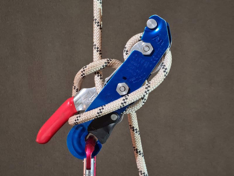
A potholing through-trip with entrances at the top and bottom of the cave. Pitches in between can be rigged using a rope that is pulled down the pitch once every person has descended, so that the same rope can be used for the next pitches. If there are no issues, then abseiling is the only thing needed, not prusiking. However, a spare rope is needed for subsequent pitches, just in case one fails to pull-through correctly. It is also normal for at least one caver to bring prusiking equipment, so that they might be able to return up a pitch and untangle the rope if needed. Uses a unique rigging style relying on a doubled rope where one end is safe for abseiling, and the other end is used to pull the rope down the pitch. Abseiling on the wrong side results in a freefall, so each person must know how to safely use it. Normally, there is no traverse line at the pitch head, since it cannot be retrieved later.
For safety, the two sides may be done with different ropes, perhaps different colours, and maybe even a very thin cord for the derigging side (since it does not need to hold the weight of a caver). This allows each caver to immediately see and feel which side is safe. Pull-throughs are only possible with anchors which are permantly left in the cave, which are smooth enough for the rope to attach directly to them and run smoothly through them, such as P-hangers, or naturals that can perform the same function.
The most common rigging uses a knot with a loop half way along the rope, with a carabiner that is clipped to it. One end of the rope is fed through the anchors, then through the carabiner, and lowered down the pitch, with a safety knot tied in it. This end is used for abseiling and prusiking. The other end, when pulled, causes the carabiner to slide down the rope, and derigs the pitch, as long as the safety knot has been untied first, and there are no tangles. This approach results in a special form of Y-hang, which is quite different from a usual Y-hang. Alternatively, a large knot can be tied in the middle of the rope, which is too large to fit through the anchors, such as a flat double overhand bend. The carabiner is not used in this case, and nothing is clipped around the rope used for abseiling and prusiking. When the rope is fed through the anchors, the knot jams against them, and supports the weight. This method is prone to the knot getting stuck in the anchor, and puts the load sideways through a single anchor, instead of in the usual direction through a pair of anchors, so it is not recommended. In the worst case, if the knot somehow managed to pull through the anchor, it would result in a freefall, which would not be possible with the Y-hang approach. It is, however, the only method that allows deviations (but not rebelays) to be reliably used, though deviation slings and carabiners cannot be recovered. This method is most often used with a single anchor, just in case it was not already controversial enough. With either approach, a failure of one of the anchors causes a significant shock load, which is worse than a normal Y-hang, so pull-thoughs are generally only used with very trustworthy anchors.
Unlike a standard Y-hang, the angle between the arms of the pull-through's Y-hang cannot be controlled, and will naturally settle to about 120°. However, because the rope passes through the anchors and between them as well, each anchor sees a force of about 193% of the load on the rope below, pulling in a direction about 15° below horizontal. This means that anchors need to hold 2.7 times the load that they would for a standard 90° Y-hang. It is not possible to control where the rope hangs between two walls of a pitch. With the knot jamming approach, the anchor that the knot jams against sees a force of 100% of the load on the rope below, pulling horizontally, while the other sees a force of 141% of the load on the rope below, pulling at an angle of 45° below horizontal. This makes it significantly less stressful on the anchors than the Y-hang approach. Again, the position of the rope cannot be controlled, and it hangs vertically below one of the anchors. Since anchors are usually placed in walls, this makes it more likely that the knot jamming approach will suffer from rub points.
The tension in the rope passing through the anchors of a pull-through's Y-hang is the same formula as for the force on the anchors of a standard Y-hang (see that section), with the angle between the arms being 120°. However, the rope pulls in two different directions on each anchor, one at the angle of the rope between the anchors (often horizontal), and one at 30° below horizontal. Because they pull with equal force to each other, this simplifies the calculations significantly. The resulting angle of pull is half way between the two directions:
0.5 × ( angle of the arm from horizontal + angle of the rope between the anchors )
which will be 15° downwards if the two anchors are at the same height as each other. The total force from the two ropes pulling on each anchor is:
2 × cos( angle of the arm from horizontal - angle of pull ) × tension in the rope passing through the anchors
The most basic pull-through approach had probably existed for a long time in sailing and mountaineering; tie a loop knot in the end of a rope, loop it around an object such as a rock, descend the rope, then try to flick the loop off the object by shaking the rope. This often failed, and mountaineers would then be forced to abandon that rope, and use another rope as needed to continue their descent. This advanced to using a doubled rope, looped around an object, such as a rock. One end could be tied to the mountaineer, or tied to a stick which they could sit on as a boatswain's chair (an ancestor of the sit harness). They could then hold the other end of the rope, and slowly lower themselves with it, the most simple version of doubled rope technique. This would allow the rope to be pulled down afterwards. This method was mentioned both for mountaineering and as a fire escape in Oekonomische Encyklopädie volume 13 (page 81) by Johann Georg Krünitz, in 1778 in Berlin, Prussia, Holy Roman Empire (now Germany). It is a far older technique, having been described during previous centuries, but this is the first time it would have made sense as a pull-through, though this aspect was not described. This then progressed to the actual pull-through; loop a bight of rope around the object, descend using one or both strands, and then pull the rope down afterwards.
Between 1860 and 1862, British mountaineer Edward Whymper invented the approach of using a separate pull-down cord tied to a metal loop which the main rope passed through after looping around an object, exactly as cavers might now use a carabiner (Scrambles Amongst the Alps, Edward Whymper, 1872, page 51). French mountaineer Jean-Estéril Charlet-Straton is perhaps the first to have documented using the more basic doubled rope technique, descending both strands at once so that one end could be pulled afterwards to retrieve the rope, which he used during an 1876 ascent of Petit Dru in the French Alps. His innovation was very minimal, and in fact was a step backwards compared with that of Edward Whymper, but at least it did not require a specially prepared rope. It is significantly more risky than Edward Whymper's approach, as it relies on both strands being pulled almost exactly the same amount, with the friction at the anchor being the maximum difference allowed between the two strands. A standard pull-through, which matches Edward Whymper's approach, only needs the load on the main loaded strand to be more than or equal to that on the strand used to pull down the rope, which will always be the case during normal use, since only a single strand is used, and the other one will not be caught by mistake with more force than the loaded strand is experiencing. However, Jean-Estéril Charlet-Straton's approach is safer from the perspective of the user not needing to know which strand is which, since both strands are used at the same time.
Cavers used variations of either approach with ladders, body abseil or handlines before SRT developed. The earliest known record of its use with ladders was by French caver Édouard-Alfred Martel in 1892 in Aven de Vigne Close, and described with ladders in 1898 in the British publication Encyclopaedia of Sport. In the second case, ladders were retrieved for use on lower hangs of the same pitch, while the rope was used as a pull-up cord on the way out. German mountaineers were depicted using both Edward Whymper's approach and a ring jamming approach in Anwendung des Seiles, published by the Bavarian section of the German Alpine Club in München in 1907. The 1930 edition then showed a variation of the knot jamming approach, in addition to Edward Whymper's approach. French cavers Pierre Chevalier, Hélène Guillemin and François Guillemin started using ropes to retrieve ladders, leaving a carabiner or metal ring (presumably a piton with a ring) at the top of the pitch holding a rope in the Dent de Crolles system near Grenoble in France in 1935. Pierre Chevalier, Fernand Petzl, and others would also use that approach to retrieve both ladders and ropes from pitches from 1940 onwards, in the same cave system. In 1944, American sailor Clifford Warren Ashley suggested several methods for retrieving a rope in the Ashley Book Of Knots (#391-399), but all of them are extremely dangerous, as they rely on slipped knots, and could accidentally untie with even a slight pull on the tail of the knot. In 1945, French mountaineer Pierre Allain created the Décrocheur, a rather terrifying device that dropped the rope down the pitch as soon as the weight is taken off the rope (later versions needed a cord to be pulled, making it marginally safer).
In 1962, British caver Tony "A.D.O." Oldham stated that an ideal knot to attach a rope in order to abseil down a cliff from a cave in Bristol's Avon Gorge, and then pull the rope down afterwards, was the highwayman's hitch. Not only is the knot incredibly easy to accidentally untie by snagging the wrong end of the rope, it also cannot cope with a significant load, and can untie itself just from the weight of a human on the correct end of the rope. Given that he was known for either legitimately copying or plagiarising other people's work (and was from Wales not Mendip), it is not known if he made up this terrible advice himself, or whether the terrible advice came from a Mendip caver. The first known SRT pull-through took place in 1968, by British cavers Paul Allen, Fred Davies, Ian Jepson, Tim Reynolds and Mike Thompson from the Wessex Cave Club, in Kingsdale Master Cave's Swinsto Hole, pulling through to Valley Entrance. Their method is not described in detail, but they almost certainly used classic abseil on a doubled rope, and pulled down the ropes by pulling either end. This was followed in 1969, by French cavers Paul Courbon, G. Dou, M. Lopez and A. Mattéoli, in the Gouffre de la Pierre-Saint-Martin, in France/Spain, using the Décrocheur. In Britain, it was described in Descent 3, in the same year. The pull-through technique with a carabiner was recreated by French caver Daniel Martinez in 1972, as an adaptation of pull-up cords, for use with cord technique. Pull-throughs with Y-hangs set up for it first appeared in France at the end of the 1970s. This was initially done using equipment such as maillons that were left in the cave, or using naturals, or cord technique. Cavers continued to use pull-throughs with ladders even after SRT developed.
This history section only covers pull-throughs. This article also has a detailed history of many of the other devices and techniques that are used for vertical caving.
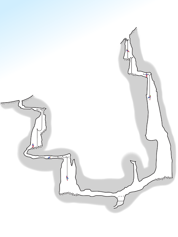
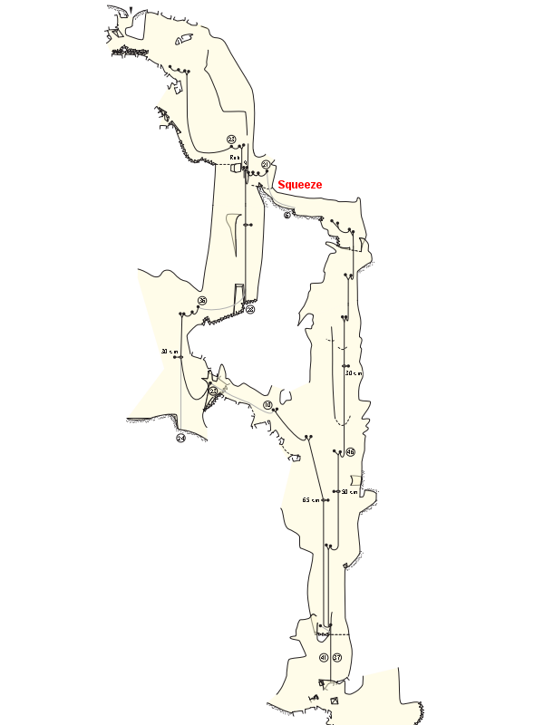
A potholing trip using two potholes that meet somewhere along their routes, or using two routes in the same pothole, where both routes contain pitches. The trip requires two separate teams, one following each route. Each team rigs their own pitches. Then they meet in the middle, swap routes, and typically derig the other route (though it may be left rigged if it will be used for other teams).
Exchange trips require planning to ensure that teams reach the middle at about the same time (unless there is something else to do while waiting for the other team), since if one route is more technical or has more pitches, the team rigging that route may need additional time. Before either team derigs, they must be certain that there are no obstacles on the other route, such as squeezes, that any member of the team derigging that route cannot get past. For that reason, the largest cavers may prefer to start on the route with the smallest squeezes. If the routes are within the same pothole, and there are pitches before the point where the routes initially split, then the teams will need a way to let the other team know that they have completed derigging their route and have exited from that point, so that the second team to reach that point will know that they can derig the upper pitches, without stranding the other team.
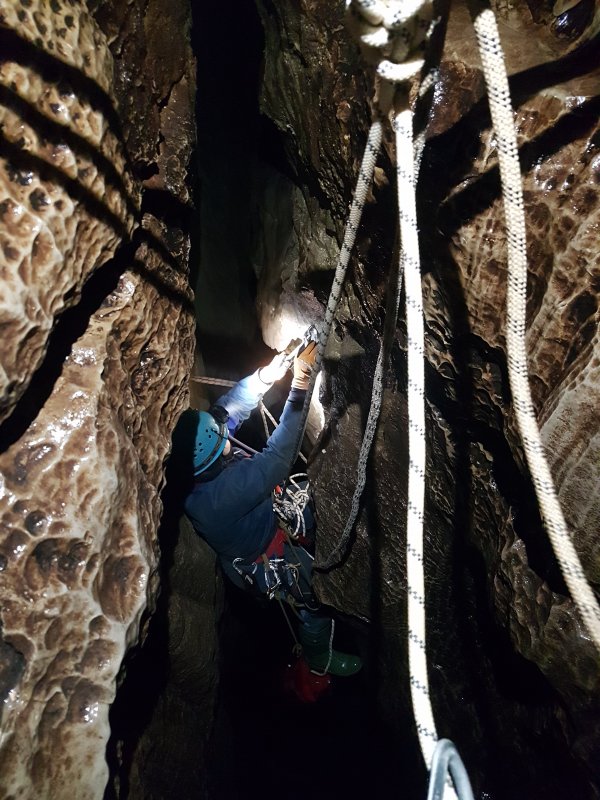
A way of lifting heavy weights, or creating a lot of tensioning force on a rope, such as when rigging a Tyrolean traverse. The loaded rope passes through a pulley, or some other device that can capture the progress, such as an auto-locking belay device. If using a basic pulley, then a second device can be added that can capture the progress, such as a strong prusik loop (or an ascender, but this can really damage the rope due to the force on the cam teeth of a normal ascender). After passing through the pulley or belay device, it aims back in the opposite direction, towards the load. It then passes through a second pulley, and turns back towards the original direction, similar to a letter Z. The second pulley has an ascender clipped onto the loaded rope, facing towards the direction of the load. When the tail of the rope is pulled, it pulls on the pulley and ascender, with the pulley halving the effort needed. It also pulls on the loaded rope via the first pulley. While there are some losses in the system, this can effectively triple the pulling power on the loaded rope.
During tensioning, the pulling force on the ascender and each of the two pulleys is twice the pulling force applied to the tail of the rope. If the tension is then captured (such as a belay device instead of the first pulley, or an ascender at that pulley), then the device that captures the tension will be subjected to three times the original pulling force. If the weight of an 80 kg caver is used to tension the system, then each pulley and ascender has to be able to cope with 160 kg during tensioning, and the progress capturing device has to cope with 240 kg. That is before adding the force of a caver using the Tyrolean traverse (assuming this is being used to tension a Tyrolean traverse). Additional pulleys can be added at each end to increase the pulling power further, and it is very easy to exceed the working load limit of the various pieces of equipment. However, it should be noted that the losses in the pulleys can be quite significant (90% efficiency is good for a pulley, while a carabiner manages only about 35-45% efficiency), and the progress capturing device is likely to lose some of the progress as it clamps the rope, so a significant amount of the tension will in fact be lost, and the pulling force will never be as high as the calculations here would suggest. For example, if the system uses a Petzl GriGri instead of the first pulley, and a 90% efficiency pulley, then the expected efficiency is only a 2.15:1 mechanical advantage, instead of a 3:1, because a GriGri has about a 28% efficiency. With the Petzl Mobile pulley used in the Z-rig illustrations, Petzl claim 71%, but measurements gave just 67% (66.66% if you want to split hairs). The Petzl Rig's efficiency was measured as just 25% (actually 24.6%) with a 10 mm rope, giving a total mechanical advantage of 1.84:1. The Petzl Rig also loses about 1.2 cm of progress every time it captures, but the exact efficiency lost there will depend on the ratio of that to the pull distance. The "change of direction" pulley was old and stiff, and only gave 61% efficiency when pulled at 90°, this reduced the efficiency of the entire system down to just 1.13:1. It helps to have good pulleys, and an efficient progress capture device! For the best efficiency, the most efficient pulleys should be as early on in the system as possible, closest to where the pulling power is put into the system. Therefore it was a very bad choice to use the stiff pulley as the "change of direction" pulley.
It is possible to put the progress capturing device at the end of the system where you pull, which reduces the amount of tension that the device has to hold to double the pulling force on the tail of the rope; useful if the tension in the loaded rope will be higher than the device is capable of. However, when using that approach, every component in the system has to remain active for the entire time that the tension is needed, and cannot be repurposed for anything else for as long as the tension needs to be maintained. That means that every component needs to be able to cope with the initial tension, as well as whatever new tension will be distributed through the system when a load is hung on the system afterwards (very important for Tyrolean traverses). The position of the pulleys and ascenders cannot be reset to add more tension, and although there are ways to do it using something called a piggyback, that again relies on having a progress capture device that can hold the full load, so it defeats the purpose of moving the progress capture device to the end of the system. If there was not enough rope in the pulley system to achieve the desired tension, then it all has to be taken apart, the main rope has to be shortened, the pulley rope has to be lengthened, and then everything has to be set up again. As a result, this is not normally used in caves where space is limited, and equipment is a precious resource. This approach is commonly used with tensioning systems for slacklines, where there is more space to work with. During tensioning, the progress capture device and each pulley should experience a force of double whatever force is used to tension the system (assuming the tensioning rope is pulled in a direction towards the load). After tensioning, the progress capture device experiences the force that was used to tension the system, while each pulley still experiences double that. If the load on the rope is changed (eg. by a caver hanging on the Tyrolean traverse), the force on each device is calculated as the force on the loaded rope, multiplied by the number of loaded rope strands that the device has emerging from it (2 for each pulley, 1 for the progress capture device), divided by the total number of rope strands connected to the loaded end of the pulley system (3 in this case, since it is a 3:1 system). It is also worth noting that efficiency is a bigger problem with that approach. With a Petzl GriGri and 90% efficiency pulleys, it is only a 0.76:1 mechanical advantage (meaning it actually loses strength rather than gaining it), because the least efficient pulley - the GriGri - is the first pulley that takes the pulling power in the system. In the illustration, the efficiencies of the actual devices in use were so poor that it only gave a 0.54:1 mechanical advantage; roughly half the efficiency that you would get from just pulling on the loaded rope!
Pulleys can be used in a variety of ways to increase the mechanical advantage further, or multiply the advantage. Multiple pulleys in a single housing are known as a block, and when these are used with more complex arrangements to gain mechanical advantage, the setup is called a block and tackle. It should be noted that with more complex arrangements, particularly where one rope passes through several pulleys, a lot of the efficiency can be lost by the dynamic nature of the rope when the pulling force is not steady, and is instead applied in little pulses. In such cases, the efficiency loss can actually end up reducing the mechanical advantage to the point that it would have been more effective to use a configuration with lower mechanical advantage. These methods are not covered here. Find a good tutorial on pulleys and mechanical advantage.
A significant consideration is how to release the tension in the system, when it is no longer needed. In cases where the load will be removed from the rope, this is not a problem. However, when used for a Tyrolean traverse, the tension remains in the system, and the progress capturing device needs to be able to release the tension while under load. For this reason, it is common to use an auto-locking belay device, a Stop, or a prusik loop as the progress capturing device, even though these may either lose some of the progress when capturing it, or may introduce significant inefficiencies into the system. These devices can allow tension to be released by pulling handles, or pushing on a friction hitch. If using a friction hitch, it needs to be one that can easily release while under tension, such as the autoblock knot, but this then comes with the risk of accidentally releasing it when it was not supposed to be. It is also frustrating to use, as it needs to be manually moved into position, to capture the tension in the first place. Using a friction hitch puts fingers in a risky position where they could get caught between a lot of cords and pulleys that are under extremely high tension, and needs to be done with great care. If using an ascender or a progress capture pulley (both of which can damage the rope, as described above), it is normally not possible to release the tension using the device itself. If even more tension can be added to the system, then it might be possible to disengage the progress capture device while the tail is being pulled, but this might not be possible, or it might be considered too risky to have fingers near the system while tension is being added. To solve this, the rope or devices may be connected to their anchors using a slipped knot. This, however, is much more risky, since the tail could be pulled by accident, releasing the load. To avoid that, the loop of the slipped knot can be tied in a stopper knot until it needs to be untied. Another alternative is to connect the progress capturing device to a descender, which is attached to a short rope. The short rope is connected to the anchor, and the descender is locked off. It can then be unlocked when needed, and allowed to release the tension.

A variety of techniques to help recover yourself after an equipment failure or injury, or to recover a fellow caver who has become hung up or incapacitated while on a rope. Some may involve creating a replacement sit harness, chest harness, descender or ascenders. Some may involve descending rope which the casualty is hanging on, and transferring a casualty's weight to your own equipment. Some may involve hoisting a casualty up a pitch or lowering them to the pitch base. This page does not cover the techniques or equipment used for this; attend a dedicated course for that.
However, special mention is made here of the one ascender prusik method or one knot prusik method, because they are sometimes mentioned as a prusiking system, when they really are self rescue systems that can be used to ascend a rope if only one ascender or prusik loop is available. With only a single ascender or prusik loop, it can be attached to the sit harness as a chest jammer. The down rope below it can be looped around the foot (creating a footloop in the main rope), and held up above the head, with a bight of it twisted around the up rope in a doubled version of the single hitch to get a better grip. The bight is then gripped tightly with the hands against the up rope, which acts as a top jammer. This ends up creating a very clumsy frog system, which requires a lot of hand strength. The one knot version is far harder, as it needs the rope to be gripped with just one hand while the other hand tries to move the prusik loop. This can be a little easier to do with a prusik loop that is long enough that it sits closer to head height, with the bight of rope from the foot being held against the down rope below it, to create a Texas system. While this requires more arm strength to pull the body close to the rope, it means that the down rope below the prusik loop is being actively pulled down at the time that the prusik knot needs to be slid upwards, so the hand lifting it does not need to pull the down rope at the same time to get it to feed through. Alternatively, a loop knot can be tied in the down rope as a footloop, then after standing and sitting, it can be untied and retied slightly higher.
The name "one knot prusik method" might also be used to mean an alternative approach, intended for situations when there is no ascender or prusik loop, and without any other equipment. The free end of the rope is used to thread a Prusik knot around the up rope, with the tail of the Prusik knot being tied around the body as a load bearing chest harness, or tied to the sit harnesses (if there is one). The down rope below the Prusik knot (not the part of the rope used to tie the Prusik knot) is used to make the footloop in the same way as before, but the awkward position of the Prusik knot will mean that it cannot be used for the frog system, so the single hitch and grip need to be done below it instead, which creates a barely functional Texas system. The grip needs to be done with just one hand. The actions are to stand up, and slide the Prusik knot a short distance up the rope with the other hand, before running out of strength, and collapsing back into the chest harness or sit harness, to be supported by the Prusik knot. This is repeated until there is enough slack to somehow tie a second knot so that the rope no longer needs to be gripped in one hand, or you collapse from exhaustion, whichever comes first. The worst part of this idea is that almost all Prusik knots need to be tied in a much thinner rope than the rope they are being tied around, while the one knot prusik method will use the same thickness of rope. While some may recommend the Blake's hitch instead of a standard Prusik knot because it should work with a prusik tether of the same diameter, it normally needs a much more flexible rope than the static rope used for SRT. It can be used more reliably with dynamic rope, and the 5/3 variation can be used with SRT ropes as long as it is very carefully set before and during use, but its grip is rather poor, and it is primarily designed for use with doubled rope technique, not SRT. As a result, this version of the one knot prusik method is largely a theoretical exercise rather than a real one.
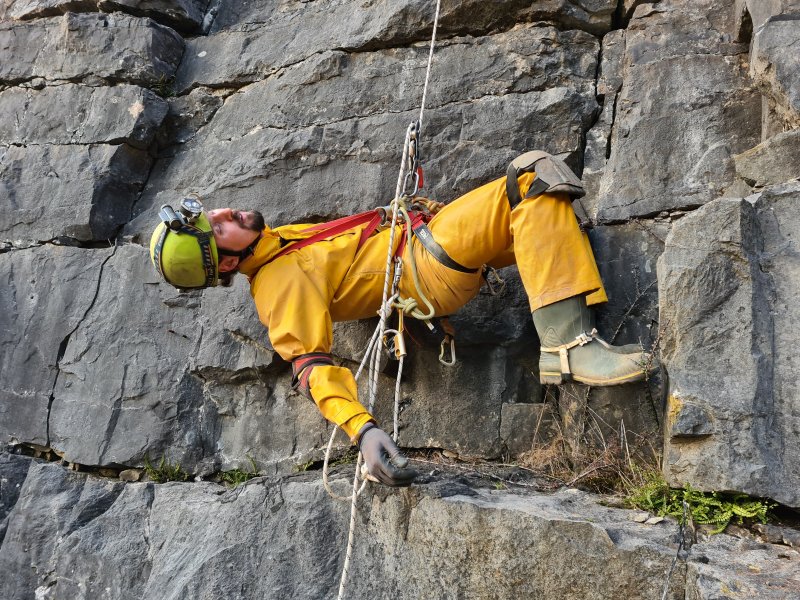
Loss of blood flow returning from the legs resulting from being held upright or sitting for too long without moving (typically 20 minutes or more, but can be as quick as 6 minutes, with symptoms starting as quickly as 2 minutes for some people). This, in turn, can cause loss of blood supply to the brain, resulting in unconsciousness. This could be while sitting in a sit harnesses or full body harness, hanging in a chest harness, standing in a rope walking harness, or just being propped upright without a harness. The effect takes place surprisingly quickly, and is most serious for an incapacitated caver hanging on a rope. Cavers who are not incapacited will notice the uncomfortable feeling in their legs before it becomes a problem, and shift their weight around, or stand up in a footloop to relieve the discomfort, and that motion in the muscles allows the blood to start flowing normally again.
The effect happens quickest when held in a standing position, and is not caused by the harness restricting blood flow. The effect takes place a little slower when held in a seated position. The effect is slowest when held lying fully forwards from an attachment point on the back of a full body harness (which includes a sit harness and chest harness), but while these are used in rope access work, they are totally impractical for caving. Chest harnesses when used alone without a sit harness produce their own breathing issues and blood flow issues in addition to the potential for suspension syncope and general discomfort. The effect does not happen at all when held in a completely horizontal position, such as when lying on a bed, or when held in a position with the legs raised above the head. (Statements claiming the opposite are sometimes repeated by cavers from areas where step systems are popular, and used as a way to promote their preferred prusiking systems. It is important to read the actual research rather than the nonsense threads by a misinformed internet warrior. It is also worth noting that almost all cavers will be in a seated position when using a descender, and there is not normally a chest harness to keep them more upright while doing so.)
After hanging that way for 3-4 hours, the effects become more serious, as muscles start to break down (rhabdomyolysis) due to lack of oxygen, and lack of blood flow causes toxins from that process to build up in those muscles. Once blood flow resumes, those toxins can cause shock syndrome. Removing the affected person from the rope, using an improvised rescue or dedicated rescue, and lying them down as soon as possible, reduces the amount of toxins and increases the chances of survival without complications. Propping someone up for a lengthy period used to be commonly advised as a way to reduce the sudden impact of the toxins, but this approach has been shown to have no overall positive effect in the situations cavers will experience, and prolongs the time that the blood is not flowing properly, increasing the severity of rhabdomyolysis. However, you should note that the author of this text is not a medical researcher, and you should take the advice here in the same way as anything else you read on the non-peer-reviewed internet; potentially inaccurate and full of mistakes. Read the actual research instead. The British Caving Association have published a summary of the research, and instructions for how best to deal with suspension syncope.
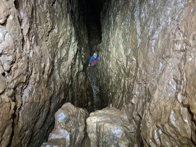
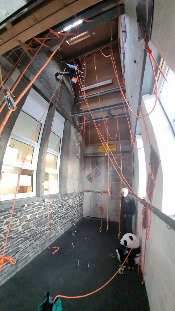
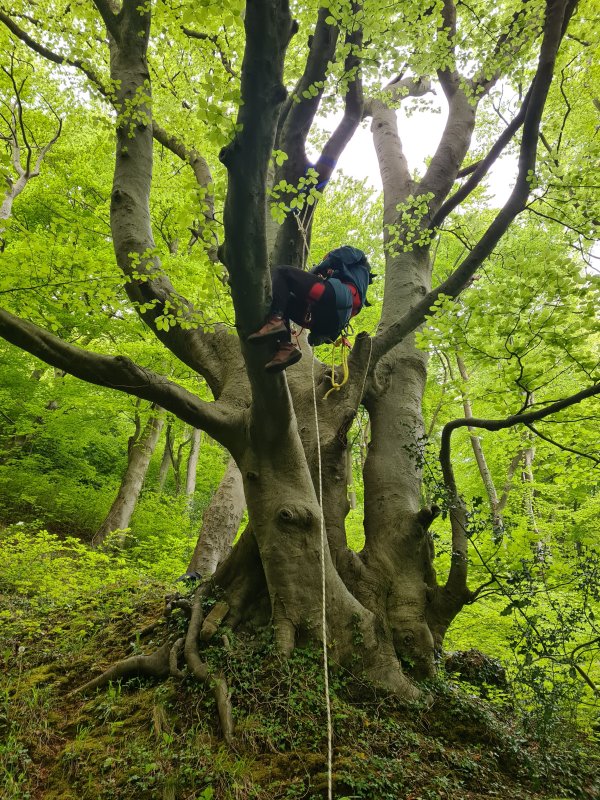
A prusiking system is an arrangement of ascenders and possibly chest rollers, and the motions that can be used for prusiking as a result. Which major parts of the body they support, whether the feet control one or more of them, whether they are connected to the relevant part of the body directly or via footloops or tethers, whether the hands have to move them upwards, and whether they sit above or below each other. Different arrangements allow different body motions in order to prusik, and some can allow more than one type of motion.
This is not an exhaustive list of prusiking systems, as virtually every caver will know a few ways to tweak their prusiking rig to gain an advantage in one way or another. Features can be taken from any of the systems, and applied to another system. Pulleys and ascenders can be clipped to virtually any part of the body for stability or comfort, and there are countless variations that can be found in use around the world. Some cavers will add a third ascender to a prusiking system that only needs two, so that if one fails, they can construct a working two ascender prusiking system with the extra ascender. However, the various systems that are in use generally fall into one of these major categories. Some of these systems can be used with prusik loops, and all of them can be used with mechanical ascenders. Some work much better with lever cam ascenders than with eccentric cam ascenders, and some work best with eccentric cam ascenders. However, all of them can be used with either type of ascender.
It is also possible for a prusiking rig to be a hybrid of more than one of these systems, so that a simple configuration change can switch it from one to the other. This is most apparent with the Mitchell system, Plummer system and Texas system, which are known as the three phase system when used as a convertible rig between those three systems. The frog system and the another prusiking system are also readily convertible between each other. A frog system rig with the chest jammer positioned slightly higher than normal and a variable length footloop can also be converted to a singe system or Texas system with a limited range of motion. A Mitchell system with a chest jammer that is not normally used can also be converted into a frog system by enabling the chest jammer and disabling the chest roller and lower jammer. The pygmy system was intended to be convertible from a Mitchell system by using variable length footloops and an extra ascender, but the conversion is quite clumsy, since it basically means carrying around an extra half of a prusiking rig. A Plummer system can be converted into a pygmy system with an optional shoulder jammer. A rope walking system can be converted to a Mitchell system by disengaging the foot jammer, and adding a footloop from the top jammer, running it through the chest roller, and using the knee jammer as a lower jammer. A rope walking system can also be converted to a Texas system by disengaging the chest roller and foot jammer, and using the knee jammer as a lower jammer. A frog system with a foot jammer can also be converted to a rope walking setup by shortening the footloop of the top jammer, placing it below the chest jammer, and adding some bungee cord to turn it into a floating cam, though the chest jammer is a bit too low to be comfortable. This conversion is known as the stair climbing method.
See below for the full list.
The order in which these systems were developed, and which one was adapted from which other one, is quite convoluted, and many of them were recreated over and over again via different paths. Rope walking appeared in Euope but was forgotten. The hands and feet system then appeared in Europe, and dominated prusiking for two centuries, slowly spreading to other continents. A variation of the Gérard Alpine technique appeared in Europe at the same time, and was used for centuries too, but not with normal ropes, and its use was confined to just one city for most of that time. The inchworm system was also developed in Europe, providing a second option for the last two decades of the 1800s. Rope walking reappeared in New Zealand at the start of the 1900s, followed by some development in Europe 20 years later. The Texas system first appeared in 1905 with poles in the USA, but was not used on ropes until decades later. The frog system, the more complete Gérard Alpine technique and then the Jumar system all appeared between 1920 and 1931, in Europe. Virtually all other systems can trace their roots back to these European systems, even the really odd ones. In fact, all prusiking systems currently in use can be traced back to the Gérard Alpine technique and the Jumar system which was derived from it, both originally developed for mountaineering, for climbing out of a crevasse after falling into it. Most of the major systems were then developed for caving, and have subsequently spread into mountaineering, rope access, arboriculture and other disciplines. I have tried to be concise without losing the important developments. Prusiking, 1973 by Robert "Bob" Thrun is a great source of information if you wanted to learn more about all the subtle little changes that went into producing the systems that exist today in America, but sadly there seems not to be an equivalent for Europe, and this information was difficult to procure in some cases. I made the following flow chart while researching this. There may be errors; some dates and origins are guesswork. Most text and flags are clickable.
This history section only covers prusiking systems. This article also has a detailed history of many of the other devices and techniques that are used for vertical caving.
These systems use either use the power from both feet at once, or just one foot. In some cases (such as the frog system), it is possible to make modifications to allow some independent motion between feet. However, in such cases, one foot is always the main driving force, and the other can sometimes work alongside it, or sometimes work in a step-like motion, or sometimes do nothing at all. It is not an essential part of the system. Almost all of these systems will provide the main body support via an ascender attached to the sit harness, giving a seated position for part of the sit-stand cycle.
Most of these systems would leave an incapacitated caver in a seated position, which gives a little more time before suspension syncope takes effect, compared with the normal positions that step systems would produce.
These systems are listed roughly in descending order of where the primary foot powered ascender is placed.
By far the most common system for prusiking, which is based on a sit-stand motion. If you do not know which one to use, you will almost certainly start with this one in Britain, and unless you decide to do some major free-hangs elsewhere, you might never even see anyone using anything else. The legs perform most of the work, and the arms are used for balance and moving the top jammer upwards. Considered to be a useful system for the use of prusik loops, but bottom weighting becomes more important, to allow the chest prusik loop to be lifted with one hand while balancing with the other.
This is the most convenient system for passing rebelays, deviations and knots. Reverse prusiking is relatively easy compared with some other techniques. Bottom weighting can be done by trapping the rope between feet before standing, using a foot jammer, looping the rope under one foot and pulling upwards with a free hand, or manually pulling the rope below the chest jammer. For most cavers, mid-rope changeovers are relatively easy, and the Italian technique can be used to make it easier when carrying heavier loads. Energy transfer efficiency is lower than rope walking and the Mitchell system, but heavier loads can be lifted, because both legs are used at the same time. Can be tiring for the arms on long pitches. It can be difficult to pass a rub point at a very sharp pitch lip, since it only has two ascenders, and if the rope below is too heavy to pull away from a lip, then one might need to be disconnected at a time, leaving only a single point of contact. Like many systems, it is a little awkward for significantly sloping pitches, because one hand needs to be used to push away from the wall, but at least one foot can be used to push away from the wall too, which makes it easier.
Uses a top jammer with a footloop and safety cord, and a chest jammer. This makes it the simplest of all the systems in terms of equipment. A foot jammer is optional, but increases efficiency, helps with bottom weighting, and optionally allows the feet to be used separately as a type of step system, essentially turning it into a hybrid of the frog system and the another prusiking system, but without the bad parts of the another prusiking system. This is still a little less efficient than proper rope walking, because the chest jammer is positioned a little too low to get good balance. However, it is a very good compromise between flexibility when passing obstacles (the foot jammer can be disengaged as needed), and efficiency when prusiking, so it is a highly recommended option. The sit harness plays an essential role both as a main support and for safety. The chest harness is only used for efficiency.
As an optional variation, an extra carabiner (or a pulley) can be attached to the D-ring below the chest jammer, and the footloop (but not the main rope) can run through it. This redirects the force on the footloop, so that even pushing outwards causes it to pull correctly downwards on the top jammer. However, it adds a significant amount of friction, and so does not give the benefit that it could have done. The carabiner needs to be made from steel, since it will be subjected to a lot of wear. The footloop must have a very small loop, since a larger loop will continually hit the carabiner, and limit the range of motion. This makes bottom weighting very difficult.
The Wisconsin system variation adds a carabiner to the chest harness above the chest jammer, and runs the footloop (but not the main rope) through it. This forces the body slightly more upright when standing. It requires the top jammer to be small (handled versions get in the way when standing, but that is what was originally used), and the footloop to have a small loop (large loops hit the carabiner) or double loop, and the chest harness to be stronger so that it can be used for support too. The smaller footloop makes bottom weighting more difficult. In its original configuration, it had two entirely separate footloops, each starting at the top jammer, both passing through the carabiner. The carabiner makes reverse prusiking much more difficult because it gets in the way of the chest jammer. To solve that, the chest jammer is attached to the D-ring via a short tether, and not attached to the chest harness at all. As a result, it requires a hand to lift it, forcing both hands to be occupied, which makes it much harder to push away from walls or perform other manoeuvres. Basically, this variation causes a lot of problems for very little gain.
The RAD system (rope ascent and descent or rapid ascent and descent) or TRAD system (tactical rapid ascent and descent) variation is sometimes used by American climbers and arborists, and is basically the frog system, with an auto-locking belay device such as a Petzl GriGri, I'D or Rig used as the chest jammer. The main difference is that a GriGri is not designed to be used in this way, so the rope does not feed nicely through it, and the down rope points upwards, which is a direction that is harder to pull. To make it easier, the top jammer has a pulley attached to it, and the down rope is fed through that pulley. The down rope can then be pulled downwards like a Z-rig while standing up in the footloop, causing it to pull through the belay device. The pulley should be positioned as high as possible on the top jammer, to allow the largest range of motion. The only real benefit to this otherwise very clumsy arrangement is that it is very easy to change between using the belay device as a descender and an ascender, rather than having to perform a mid-rope changeover. However, it makes prusiking very awkward, as one hand is stuck pulling the down rope, and cannot be used for balance. It also wastes a lot of energy by using a very inefficient belay device as an ascender, but partially makes up for that by having some mechanical avantage gained by pulling on the down rope, which is added to the force produced by the legs. While this advantage should theoretically be useful, it is completely wasted by using a high friction device like a GriGri, and by not allowing both hands to be used for balance. When testing, the Z-rig part had a 1.85:1 mechanical advantage, minus losses from the GriGri's locking distance, giving a maximum lift benefit of about 20-25 kg from pulling downwards with one hand in an awkward position. However, the loss of force from not being able to use the hand normally on the ascender is about 25-30 kg, resulting in a net loss of 5 kg, rather than a gain from the mechanical advantage. The result is that it simply makes prusiking more awkward and clumsy, but most functionality is the same as the normal frog system. The GriGri normally wastes a short distance to engage the lock, but can sometimes fail to lock completely if the down rope is released, since it relies on there being friction on the down rope, and this results in more wasted effort. It would potentially be possible to use the RAD system with a foot jammer on the down rope, and this would in fact allow the mechanical advatage to be used to much greater effect, but it forces that foot to move three times as much as the other foot during each sit-stand cycle. (Note that this is very different from what Petzl calls their RAD SYSTEM, in uppercase, meaning Rescue And Descent.)
In rare cases, the RAD system variation might be used without a footloop by someone who is unable to use their legs. This might theoretically also be used for improvised rescue, but if someone needs that much help, they are unlikely to be able to effectively use this approach. It would be limited to situations where someone has been injured enough for their legs not to work, but not so much that swinging around on a rope is too agonising, and having arms remaining perfectly strong, in a cave with a simple pitch with a convenient pitch head, that is short enough for their energy reserves. For best results, a progress capture pulley is used as a chest jammer, which is much more efficient than a GriGri. The top jammer has no footloop. Again, the rope below the progress capture pulley is passsed up through a pulley attached to the top jammer. To ascend, the top jammer is lifted, then the down rope from the upper pulley is pulled by hand. Less of a frog kick, and more of a doggy paddle. This results in a painfully slow ascent, requiring less than half of the body weight to be pulled on the down rope (actually a 2.27:1 mechanical advantage in testing with real pulleys). However, it is impossible to perform a mid-rope changeover unless the progress capture device is able to function as a descender, such as a GriGri, which then wastes another 20% of the effort (1.85:1, as above). Deviations can be passed. Rebelays are impractical, and need the down rope to be pulled with just one hand while disengaging the progress capturing. They also require a very long rebelay loop without any significant pendulum loop. Reverse prusiking requires the same one-handed operation, and seriously risks accidentally mangling hands in one of the pulleys. Y-hangs and knots cannot be passed. Bottom weighting is not required. Basically, this is great for a stunt or a show of stamina, but is utterly impractical in real caving situations. This variation causes a lot of strain on the hands, and risks rope burns more than any other system, so gloves are essential. This makes it even more likely that fingers can get accidentally caught in a pulley.
This was the first prusiking system intended to be used for caving, developed by French caver Léon Pérot in 1920 for use with his mechanical ascenders, using a chest jammer attached to a waist belt, and a top jammer attached to a footloop. However, since the ascenders never made it out of the prototype stage, it is unlikely that the system was used in a cave at that stage. This system was then re-invented by Austrian mountaineer Karl Prusik, published in 1931, and reprinted in 1932. His developments came shortly after his club had published details of the Gérard Alpine technique, and it was almost certainly derived from that, though he failed to credit the source, and basically plagiarised a lot of the work in his article. It was intended to be used instead of the Jumar system in emergencies, if one leg was incapacitated. However, it then seems to have been forgotten for a few decades. He described the chest prusik loop being connected to an improvised sit harness, and the top prusik loop being connected to a footloop for a single foot. It is possible that he intended for the footloop to run through the chest harness, but this was not clearly specified. By 1944, cavers in the Grenoble region of France were using the singe system, and all that needed to happen to turn this into the Frog system was that the lower jammer needed to be moved above the chest jammer, with a longer footloop. In 1955, American caver Dan Bloxsom re-invented the frog system as a way to recover from an abseiling emergency, which he called the fourth sling. It used a seat shoulder abseil configuration as a descender (though it would work with any descender) which doubled up as the chest jammer when the down rope was held. A footloop was attached to an upper prusik loop connected to the chest harness. The upper prusik loop, which originated as part of the Gérard Alpine technique, was intended to be used as a safety backup while abseiling, and the footloop was used to get over the lip of a pitch. However, the combination produced a working frog system which could be used to prusik if needed.
After commercial mechanical ascenders became popular, Bruno Dressler made a relatively small ascender in 1963 in the Grenoble region of France. It was tested by multiple cavers from 1964-1965, and later made by Petzl's founder in 1968, based on Bruno Dressler's design. It was not, however, initially important in the development of the frog system. The Wisconsin system was created independently by American cavers Dick Boyd, Carl Poster and Bob Olmstead from the University of Wisconsin for mechanical ascenders in 1965-1966, apparently without any knowledge of the system existing in Europe twice already by that stage. They described it in The Wisconsin Speleologist in 1966, saying that it was largely developed in 1965 and that the testing and refining process then took 6 months before publication. It was made as an adaptation of the Jumar system, the Texas system and the Plummer system. Prusiking, 1973 by Robert "Bob" Thrun gives more details. Their version mandated the use of two separate footloops from the top jammer, one to each foot for the sake of symmetry, which had to run through a carabiner on the chest harness. It was probably the first variation of the frog system to be used underground, though there are no details of when or where it was used. It then faded into obscurity and was largely forgotten about, despite coming very close to creating the now dominant frog system.
The frog system as it is now known was redeveloped between 1966 and 1968 by French caver André "Ded" Meozzi, in the Grenoble region of France, and it is known there as the Ded system, as a result. The motion is similar to a swimming frog kick, and the technique originated (twice!) in France, hence the common English name. André "Ded" Meozzi taught it to his club Spéléo-Club de la Tronche, who very quickly realised how much better it was than the systems they had previously been using. This would allow them all to be capable of using it, rather than relying on one person to prusik up a pitch to prepare a ladder for the others. Most of them used a Jumar for the chest jammer, and a Bruno Dressler ascender for the top jammer. The Bruno Dressler ascender was not used as a chest jammer because it needed to be detached from the D-ring to connect the rope, meaning that the sit harness could fall off in the process. Safety cords were not used.
When Wessex Cave Club and future Cambridge University Caving Club member Nick Reckert was taught to prusik in France in 1970 by the Spéléo Club de Rouen, he was taught to use the frog system. According to him (personal communication), no chest harness was used, and the single foot's footloop was passed through the carabiner that was being used as a D-ring, which would have added a lot of friction. It did not have a safety cord. The chest jammer was connected directly to that carabiner, and will have needed to be pulled upwards by hand. It is not known exactly when footloop started being passed through that carabiner, but it is likely to have been part of the initial 1966-1968 experimental arrangements for the frog system. He used two Petzl Basic ascenders. The sit harness was a Dülfer seat made from a sling. He started to teach to Cambridge University Caving Club members this technique in 1970, and this is the first time the frog system is known to have been used in Britain. In 1971, American caver Richard Weisbrod described how the inchworm system's mar-bar could be taken off the feet, and used as a top jammer in the hands, which is supposed to be more useful on tight pitches. When doing so, it basically becomes the frog system, but without its footloop, which makes it incredibly strenuous and very clumsy.
During the 1971-1972 preparation for the British expedition to Ghar Parau in Iran in 1972, cavers also reinvented the frog system, seemingly without realising that it existed in France and Britain already, and it was the most commonly used system on the expedition. It was almost certainly developed from the Jumar system, which had previously been used by the same cavers. Peter Standing wrote about it, and John Allonby was one of the ones using it, while Glyn Edwards may have helped develop it, with cavers being a mix from Northern England, the Midlands and Mendip. In that configuration, the chest jammer was connected to the sit harness via a very short tether or sling (like the Wisconsin rig), and there was no chest harness. The top jammer did not have a safety cord, and was powered by a single foot. It did not pass the footloop through a carabiner the way that Nick Reckert had been taught, and seems to have been developed independently, as the expedition did not feature any of the people that Nick Reckert had taught. The same approach was used by the University of Bristol Spelaeological Society during an expedition to Slovenia in 1972, but since they shared some members with the Ghar Parau expedition, it is likely that they did not independently create it. A safety cord to the top jammer was suggested for use with this variation.
Initial resistance to the frog system from other French clubs disappeared after the Ecole Française de Spéléologie (EFS, the French caving school) asked the club to provide training to other clubs, starting in 1972. It then spread to cavers in other regions. However, it was not until 1975 that Petzl's Jean-Louis Rocourt suggested making a dedicated chest ascender based on Bruno Dressler's design, allowing this system to rapidly become dominant.
As well as being the nickname of its creator, Croatian cavers Vlado Božic and Hrvoje Malinar conjectured that "Ded" (meaning "Grandfather") is an abbreviation of the word "deductif", meaning that it was derived from two previous techniques used in Germany and America, that were popular with Jumar ascenders. Apart from the singe system that French cavers had been using before then, it is likely that only the Jumar system was known in that part of France at that time, so those two systems are the most likely source of inspiration behind the frog system. The inchworm system was only recreated in that same year (so would not have had time to reach France yet), and the Jumar system and inchworm system are the only two other systems that French cavers Jean Claude Dobrilla (who had also been on an expedition with Nick Reckert in 1970) and Georges Marbach wrote about in the first edition of Techniques de la Spéléologie Alpine in 1973, so it is unlikely that any other systems inspired the frog system. This appears to be the first widely published instruction manual that included the frog system, and both authors were members of the Spéléo-Club de la Tronche. It recommended the use of a safety cord for the top jammer, but the photographs showed cavers not using one, which implies that the book authors are the first to suggest its use in France. At the time, they called it an "American strap", showing its origin. At that time, only a single footloop was used, for just one foot, with the other foot only being used to counterbalance. The common bottom weighting method of trapping the rope between the feet had not been developed, but it appeared fairly soon afterwards, probably around 1978, when cavers were using two feet in the footloop, in order to lift heavier loads. A foot jammer was suggested by John Forder in the BCRA publication Cave Science volume 9, 1982, using the floating cam approach from rope walking. The dedicated foot jammer for use with the frog system appeared in 1990, with the French Millet 9400 Aphanicé-Boulourd. However, it was not until Petzl released the much more convenient Pantin in 1999 that it became popular to use a foot jammer with the frog system. The frog system started to take over from the other systems in North America during the early 1990s.
The RAD system variation was created by Canadians Robert Chisnall and Michel Goulet of Multi-Trek during 1991 and 1992, as a modification of the frog system that could be used with the newly released GriGri, inspired by a Petzl handled ascender that had a pulley on it, which presumably had been made for the Italian technique. It was intended for use with rescue services, to make it easy to adjust position on a rope relative to a stretcher or the rock, but it soon became more common with arborists and climbers. According to both of its inventors (personal communication), it was originally described as being usable both with and without a footloop, and when used with a footloop, it was typically made from an etrier. It was used in all of these configurations by several people, including wheelchair-bound children at an adventure camp, who used it without a footloop. Initially, the pulley on the top jammer was hung below it, but the pulley was soon moved to the top of the ascender, to allow a little more movement. By the mid 1990s, this was being taught to the Royal Canadian Mounted Police and other rescue services, and was renamed to the tactical rapid ascent and descent system, as a humorous reference to how the word "tactical" and black painted devices would double their price. It was then spread to American rescue services and climbers at the International Technical Rescue Symposium in 2000, and entered the arboriculture world by 2005. Many use it without the pulley, turning it back into a very inefficient basic frog system. The variation without a footloop was most famously used by paraplegic climber 黎志偉 (Lai Chi-wai) in 2016 to ascend a 55-65 metre cliff on Lion Rock in Hong Kong, and in 2021 to ascend 250 metres up Nina Tower in Hong Kong. He probably started to use the technique in about 2014-2015. Much later, a few others have claimed to have invented this system, and one of them referred to it as the yo-yo system. However, given that their approaches are identical to the standard RAD system, it is unlikely that they actually independently invented it.
This history section only covers the frog system. This article also has a detailed history of many of the other devices and techniques that are used for vertical caving.
A slight variation of the frog system, that can be used to lift heavier loads, which is useful when hauling large amounts of equipment, or during improvised rescues, or when muscles are tired. Cannot be easily used for prusik loops, unless the top prusik loop is short enough to fit a pulley between it and the D-ring.
Passing rebelays, deviations, reverse prusiking, bottom weighting, and most other things are identical to the frog system. Makes mid-rope changeovers easier for some cavers, which also means passing a knot can be easier too. The main benefit is a double or triple power advantage. However, it does so at the expense of preventing convenient use of a foot jammer (since that cannot have the power enhancement). It also reduces the amount moved per standing cycle. This can make some improvised rescue techniques more awkward in cases where a larger movement might be needed to lift a casualty off their equipment.
For the Mao variation of the Italian technique, the footloop is connected to the top of the chest jammer or D-ring, then via a pulley which is clipped to the bottom of the top jammer, and then down to the feet as normal. This halves the energy expediture during each sit-stand cycle, but also halves the height gained. Another variation is the Ded-Mao-pompe, where the footloop's cord starts at the top jammer, passes through a pulley at the footloop, then back up through a pulley at the top jammer, then down to where it is clipped to the top of the chest jammer. This now gives triple the power, but a third of the height gain. The sit harness plays an essential role both as a main support and for safety. The chest harness is only used for efficiency.
This prusiking system was developed in Italy in 1974, but its creator is not known. The Ded-Mao-pompe variation was first described by French cavers Bruno Dressler and Pierre Minvielle in La Spéléo in 1979. Petzl produced the first dedicated top jammer for this system in 1991, and released it in 1993.
This history section only covers the Italian technique. This article also has a detailed history of many of the other devices and techniques that are used for vertical caving.
A sit-stand system for prusiking using components that can be constructed from parts of the Mitchell system. The legs perform a lot of the work. The arms are each used for moving an ascender upwards, but also have to be used to control balance and pull the body close to the rope since there is nothing holding the body close to the rope otherwise. It is basically an upside down frog system. Considered to be a useful system for the use of prusik loops, and is often suggested for that purpose in mountaineering, even though it really is far less convenient than the frog system. It does have the benefit that the down rope is under tension when standing, so it is easier to move the prusik loops than the frog system, but the stress on the arms when standing removes the benefit. It remains in use for vertical caving, both on its own and in cases where it has been converted from the Mitchell system, typically in regions where indestructible rope technique is used. There are two possible motions. The first has the legs tucked into a squatting position beneath the body during the sitting part of the cycle, but this significantly reduces the amount of motion per sit-stand cycle. The second has the legs kicked out in front of the body during the sitting part of the cycle, which puts more strain on the arms, but dramatically increases the height gained per sit-stand cycle. It is almost always used with the second motion.
Somewhere between the frog system and Mitchell system in terms of convenience when passing rebelays and deviations, being relatively uncomplicated for both, but not quite as convenient as the frog system. It is extremely difficult to use for passing a knot while abseiling, but relatively easy when prusiking. Reverse prusiking is relatively easy compared with some other techniques. Bottom weighting is done by manually pulling the rope below the lower jammer, or using a separate foot jammer (which is not part of the usual configuration for the this system). Another option is to push the cam open of the lower jammer, but this really is very fiddly. Mid-rope changeovers are relatively easy. Very poor energy transfer efficiency, with a clumsy motion and stressful seating position. Considered to be very strenuous on a free-hang, and tiring for the arms on long pitches. This system will temporarily leave the caver in an uncomfortable situation if the top jammer fails, as after a significant loss of height, they will be held at an awkward angle until they can remove their feet from the footloop. An incapacitated caver could be held in a very awkward position, depending on what part of the sit-stand cycle they were caught in.
Uses a top jammer without a footloop and a lower jammer with a footloop. Both ascenders have safety cords. The top jammer's safety cord is often passed through a carabiner that is clipped to the chest harness to try to pull the body a little closer to the rope. The sit harness plays an essential role both as a main support and for safety. The chest harness plays only a minor role for efficiency, and the system could be used without it.
The three phase system can operate in three modes (described in that section). When its quick attachment safety is connected directly to the rope and the top jammer is removed, it acts like a replacement top jammer, turning it into the Texas system.
In 1905, steeplejacks in New York had developed the Texas system as a safer alternative to the two-knot variation of the Gérard Alpine technique, which they had previously used to climb flagpoles for painting or servicing. Several accidents had previously happened where steeplejacks had fallen over backwards, but the Texas system allowed them to hold the body upright more reliably if the legs swung to the other side of the flagpole. In their original version, they used a pair of nooses as friction hitches to grip the flagpole. The lower noose had a footloop hanging from it, used by a single foot. The upper noose had a cord ending in a loop of canvas, which was tied around the other thigh, instead of the waist, which functioned as a sit harness. This had been developed very recently when it was first photographed in 1905, most likely in the same year, since it was developed while painting flagpoles on the Parker Building that only existed between 1900 and 1908, and only the older method was described in 1901. It was then described as a new safety enhancement in 1908, called steeplejack's flagpole slings. By 1918, the boatswain's chair had been adopted as a better sit harness than the leg loop (probably as early as 1910), and the method was advised to American steeplejacks by the American government. The lower noose still had a single footloop. In 1944, American steeplejack Laurie Young described in The Ashley Book of Knots (#454) how steeplejacks from Massachusetts, USA were climbing poles using this method, so it had clearly become common among steeplejacks on the eastern coast of the USA. While this was still used with poles such as flagpoles, the steeplejack's hitch (which the steeplejacks also used by then) would have worked just as well on ropes, and the rest was identical to what cavers would later use.
This system was in use with caving since 1960, and appears to have been redeveloped by cavers from Austin, Texas, USA, for use with prusik loops. It is essentially the same thing as the singe system, with the chest jammer put on a long tether. However, it seems to have been developed independently, as an adaptation of the Gérard Alpine technique, with the chest prusik loop moved to a sit harness, and then the pointless second foot prusik loop replaced with a single one. The result was so close to the approach used by steeplejacks, that it is possible it had some influence from that direction too, but this seems unlikely due to the very different locations, and the lack of knowledge transfer from other regions to Texan cavers at that time. Originally, it used a boatswain's chair as a sit harness. In its original format, only one foot was used in a single footloop, but the idea of using both feet together was described by American caver Tom Perera in 1962, without giving either approach a name. Both approaches may have been in use as early as 1960. Both the squatting and kicking approaches were in use already by 1962, and were most likely developed in 1960. In 1962, Tom Perera also mentioned that to get over a lip, an additional footloop and prusik loop could be used above the other prusik loops instead of the main foot prusik loop, turning it for just a moment into something closer to the frog system. He also mentioned that while the boatswain's chair was preferred, some cavers had been using a standard sit harness or improvised sit harness, probably for the last 2 years.
Some cavers had been using the Texas system with mechanical ascenders, described without giving it a name by American cavers Dick Boyd, Carl Poster and Bob Olmstead while talking about the Wisconsin system variation of the frog system in 1966, but researched the year before. The boatswain's chair was not mentioned, and may have fallen out of fashion by then. American caver William Franklin "Vertical Bill" Cuddington developed the three phase system variation some time between 1969 and 1974, at which point it became more common to use mechanical ascenders with the Texas system. Robert "Bob" Thrun classified the kicking approach as a "long kick" in Prusiking, 1973.
This history section only covers the Texas system. This article also has a detailed history of many of the other devices and techniques that are used for vertical caving.
An uncommon sit-stand system for prusiking which is half way between the frog system and the Texas system. It ends up similar to the inchworm system, but is significantly easier to use for some manoevers. In its original format, it lacked any safety, but it is easy enough to add it. The legs perform most of the work, and the arms are used for balance and pulling up the lower jammer. However, it allows a very limited range of motion, and as a result the gain feels a little limited considering the effort. Can be used for prusik loops, but the position of the lower prusik loop makes this somewhat awkward.
This is a reasonably convenient system for passing rebelays and deviations. It can be used for passing a knot while abseiling or prusiking, but the position of the lower jammer makes this more awkward while abseiling. Reverse prusiking is relatively easy compared with some other techniques. Bottom weighting can be done by looping the rope under one foot and pulling upwards with one hand. If using a Gibbs ascender (the type of ascender this system was originally created for), bottom weighting is not needed, as the ascender will effortlessly lift up if you pull up on the end of the ascender's lever. Mid-rope changeovers are possible, but a little clumsy because of the low position of the lower jammer. The positions of the ascenders does not leave much space for the lower jammer to move, so it is not possible to fully sit before standing. So although resting is comfortable, energy transfer efficiency is slightly lower than the frog system, because of the limited range of motion. One arm has to alternate between holding the rope for stability, and pulling up the lower jammer, which is less convenient than the frog system. This system will temporarily leave the caver in an uncomfortable situation if the chest jammer fails, as after a significant loss of height, they will be held at an awkward angle until they can remove their feet from the footloop.
Uses a chest jammer and a lower jammer with a footloop. A safety cord was not originally used, but it needs to be used for the lower jammer, so that the lower jammer can take over if the chest jammer fails, and to avoid dropping it during manoeuvres. This makes it the equal simplest of all the systems in terms of equipment (along with the frog system). The sit harness plays an essential role both as a main support and for safety. The chest harness is only used for efficiency, and was originally used only for comfort. A longer safety cord also makes it possible to pull up the lower ascender using the safety cord, so it can be put lower down, increasing the range of motion and efficiency. However, that then makes it much harder to reverse prusik, and harder to perform most manoevers.
The portly prusik recreates this system with a slightly different arrangement, intended specifically for larger cavers. A shoulder jammer is used instead of a chest jammer, so that the stance can be more upright. A double footloop is used to allow the feet to be further apart (the double footloop was also used un the original version).
An incredibly silly variation can be used to gain a tiny bit of extra height per sit-stand cycle. While this could be used with one foot in a single footloop, its entire purpose is a performance gain, so it makes sense to use both feet in a single or double footloop. The chest jammer can be connected to a mobile carabiner that can slide up a very tight tether between the chest harness and sit harness. After standing and lifting the chest jammer as high as possible, rock backwards upside-down, slide the chest jammer down the tether closer to the harness. While upside down, pull the lower jammer all the way up until it touches the chest jammer. Rock back upright, and stand up, to repeat the cycle. Not only does this look quite ridiculous during use, it takes extra time and far more strength to perform the rocking, which could have been more effectively used by performing two normal sit-stand cycles with a regular singe system. Nevertheless, someone actually developed and used this variation, and shared it with enough other people for it to end up in a book! Clearly, it was created by a monkey that got accidentally released into the hall at an American National Speleological Society convention.
This was the second system to be used for prusiking in a cave, having been developed between 1935 and 1944, probably by French caver Henri "Kiki" Brenot, and perhaps others such as Robert de Joly and Henry P. Guérin. It was described in French caver Henry P. Guérin's 1944 book "Spéléologie, manuel technique; Le matériel et son emploi Les explorations". It was intended to be used with the Singes Mécaniques (mechanical monkeys) ascenders. In that original format, it used a fancy full body harness (highly advanced for its time), and an oversized bracket to connect to the lever arm of the ascender. The lower jammer used either a single or double footloop to connect to one or two feet as needed. It was probably in use all the way until 1968. It is likely to have then been adapted into the frog system, with the lower jammer moved above the chest jammer, with a longer footloop, creating a top jammer. The system then fell out of use in Europe.
Robert "Bob" Thrun describes a recreation of this system for prusik loops as method 16 in Prusiking, 1973, but it was likely something that was created much earlier, probably before 1965, and almost certainly originated from the Gérard Alpine technique. The chest prusik loop connected to a chest harness, and the feet had a double footloop. Some time after the inchworm system was recreated in 1966, and before 1973, other users of that system modified it to remove the mar-bar and replace it with a lower jammer (or prusik loop) with a double footloop, recreated the singe system. They called it the number one Texas system, without realising it was something that already existed with a name. It was described in American Caves and Caving by William R. Halliday in 1974, but it is not known who developed it. Robert "Bob" Thrun described the rocking upside down variation as method 18 in Prusiking, 1973, but did not say who created it or when. It almost certainly was derived from the inchworm system (or at least, it only makes sense using handled ascenders, when testing - yes of course I tested it), and was intended for use with mechanical ascenders. The singe system was recreated again by Bruce W. Smith in 1983 as the portly prusik, as an adaptation of the Texas system, using approaches from rope walking.
This history section only covers the singe system. This article also has a detailed history of many of the other devices and techniques that are used for vertical caving.
An uncommon sit-stand system for prusiking, which should be avoided due to its complete lack of safety features, and its serious limitations. The legs perform most of the work, and the arms are used for balance. It has almost none of the major benefits of the frog system, and it is far better to use the frog system instead. Cannot be used for prusik loops. This system is still sometimes used by arborists, often combined with doubled rope technique, where it still lacks safety features.
This system offers absolutely no safety features and no redundancy. The chest jammer is the only ascender that can be safely relied on. A failure of the chest jammer results in falling upside down, and hanging by the mar-bar attached to the foot jammer. The mar-bar is not attached to the sit harness in any way and can simply slip off the feet, resulting in plummeting down the pitch, head first. Many designs would not be able to cope with the weight of a caver on the straps, and would simply break under the strain, producing the same result. Even if the caver is somehow able to hold themselves by their feet, and their home made equipment is capable of taking their weight on the straps, the rope can pull onto the top of the foot jammer's cam, forcing it open. Although with most ascenders, the safety catch will prevent them fully opening, it results in the entire weight of the caver being put onto just a few of the teeth of the cam. They are not designed to be loaded that way, and could damage the rope, or simply fail to grip and cause the caver to rapidly scrape down the rope all the way to the bottom of the pitch, head first. Even if the teeth somehow manage to take the weight of the caver, they are left hanging upside down by their feet, a position that they have absolutely no way to recover from. While a safety carabiner can be used to reduce the chances of toppling over backwards, it still does not solve the lack of redundancy, and slipping out of the foot strap because of the sudden movement when the chest jammer fails, results in a fall until the safety carabiner slams into the top of the foot jammer, possibly breaking one of them, and once again resulting in plummeting down the pitch. This system does not satisfy even the most basic safety requirements.
This system is similar to the frog system when passing rebelays, but relies more on a cows tails to avoid toppling over, which could be very serious. It is inconvenient to use when passing deviations, especially for deviations that pull the rope a long way from vertical. It is almost impossible to perform a mid-rope changeover, depending on the descender and how it is locked off, so a small problem that could normally be solved by that manoeuvre results instead in being hung up. It cannot be used safely for passing a knot while prusiking because the cows tail has to be unclipped before the ascenders can be tested, though it can be used to pass a knot if that limitation is ignored. It is nearly impossible to use for passing a knot while abseiling, due to being unable to perform a mid-rope changeover. Reverse prusiking is very difficult and forces you to curl up almost upside down, due to the position of the foot jammer. Comical while practicing, much less funny when it is needed above a huge drop. At least it is not as bad as the another prusiking system. Bottom weighting is done by pulling the rope upwards while trying not to lose your balance. It is awkward for slightly sloping pitches, since both feet are stuck together, and cannot move independently to push away from a wall, but at least both hands can be used while leaning into a steeper slope. This system is identical to the frog system, in terms of energy transfer efficiency. Taking a rest is comfortable. Yay?
The foot jammer arrangement is very bulky to carry, and awkward in tight pitches due to its fixed width. Disconnecting the foot jammer to pass a knot, rebelay or Y-hang, or to fit through a narrow gap, brings the very real risk of dropping it down a pitch, and being hung up as a result. This system also does not work well for tandem prusiking, since the arrangement of the ascenders causes the caver to rock backwards and forwards when a caver beneath them moves on the rope, resulting in motion sickness.
Uses a chest jammer and a handled for caving foot jammer when used for caving. For arborists, a simple foot jammer may be used, connected to just one foot. For caving, the foot jammer is bolted to a mar-bar, so that the ascender sits between the feet, and the feet rest on the mar-bar. The mar-bar strap passes over both feet. This strap is what causes the foot jammer to be lifted when the feet are raised, and would be used to catch an upside down caver after a failure of the chest jammer. Since it is highly unlikely to be useful in that emergency, a safety carabiner can optionally be clipped to the D-ring, and around the rope between the ascenders. This may help to keep a caver upright, or to catch the top of the foot jammer in the event of a failure of the chest jammer. It is a highly recommended option, but it would be even better to use a top jammer above the chest jammer with a safety cord, turning it into the frog system. Or to put that in other words, don't use the inchworm, use the frog system. For ascending tight pitches or getting over a lip, the recommendation is to remove the foot jammer, attach it to the rope above the chest jammer, and use it for the hands instead, pulling up on it using the strength of the arms instead of the legs (this risks dropping it, and prevents the safety carabiner from working as a safety feature). This makes it the same as the frog system used without its footloop, and is nearly impossible to do when tired. The sit harness plays an essential role both as a main support and for safety. The chest harness is only used for efficiency.
French roofers and plumbers have been described using a knotted rope to climb buildings from as early as 1684, though the technique is almost certainly much older. It was later used by exterior decorators, and while it was not actually prusiking, it used the same basic approach as the Gérard Alpine technique, and would inspire prusiking techniques.
The inchworm system was invented by German inventor Ed. von Mengden in 1879, derived from the hands and feet system, using clamping jaws ascenders, with one of them held in a large housing on the chest attached to a full body harness, leaving the hands free for performing tasks such as building work. The foot jammer needed both feet to be used at the same time. In 1913, Austrian inventor Johann Machek reimagined the inchworm system with the body held in a boatswain's chair below the ascender, and this is likely to have been influenced by Ed. von Mengden's approach, even though he had used a different type of ascender. It is likely to have also been indirectly inspired by the existing method of climbing knotted ropes, since it was intended for use by exterior decorators, but it is more likely to have been inspired directly by the Texas system which had been adapted from it, since it uses an extremely similar approach. The foot jammer was connected to a pair of shoes, and gripped the rope when the shoes were tilted correctly.
This system was then re-invented by American caver Charley Townsend in 1965-1966 in California, for use with mechanical ascenders, after a mishap during the 1965 American National Speleological Convention. Whatever that mishap was, it cannot have been worse than the potential for mishaps that this system offers. Presumably, he had been using the Jumar system in 1965, which at that point probably had no safety cords. In the original demonstration in 1966, it was called the "armless, double-foot and seat-chest sling ascending method", a mouthful which fortunately did not survive, as other cavers then came up with its more familiar name. In that configuration, it used the mar-bar. It was probably first used for caving by Charley Townsend. In 1971, American caver Richard Weisbrod described how the mar-bar could be taken off the feet, and used as a top jammer in the hands, without a footloop, which is supposed to be more useful on tight pitches. This was published in Cal Caver Vol. 22 No. 5, and the advice was then shared more widely in Nylon Highway No. 5 in 1976. In 1987, the American National Speleological Society recommended having a long safety cord to the foot jammer, but this would mean a very significant 3 metre fall if the chest jammer fails, potentially damaging either the caver or the rope, following which it would be impossible to recover, since the foot jammer would be out of reach. While it is better than nothing, it would be better to simply not use the inchworm system.
The inchworm system remains in use in arboriculture, where it was initially used with a mar-bar since around 1992, though that usage was last mentioned in arborist literature in 2007. However, since around 1995, arborists had been using the frog system and three ascender version of the rope walking system, typically with a single foot jammer. The inchworm system survived as a result of being convertible from both of those systems, where the top jammer or knee jammer was simply not connected for short ascents. This resulted in the inchworm system being used with a single foot, leaving the other foot free to manually walk up the tree. It can also be created when the Texas system using prusik loops (previously used with doubled rope technique) is replaced with directly attached ascenders, or when manually gripping the rope with feet while using doubled rope technique is replaced with a single foot jammer.
This history section only covers the inchworm system. This article also has a detailed history of many of the other devices and techniques that are used for vertical caving.
A system for prusiking which is not appropriate at all for caving, and is mentioned here only for the sake of completeness, since for a long time, it was the main method of prusiking, and inspired many other prusiking systems. While it is not really a sit-stand system, it is included in this section because it requires a similar motion, where the feet are used together. The legs perform half of the work, and the arms perform the other half. The motion used is to stand, and lift the top jammer as high as possible, hang from it by the hands, and lift the feet and foot jammer as high as possible, optionally performing a pull-up on the top jammer to gain more height, then repeat. This system should be avoided due to its complete lack of safety features, and its serious limitations. Cannot be used for prusik loops.
This system offers absolutely no safety features and no redundancy. The top jammer is the only ascender that can be safely relied on. A failure of the top jammer results in falling upside down, and hanging by the foot jammer. The foot jammer is not attached to the sit harness in any way and most likely would be pulled in a way that would cause it to disconnect from the rope, resulting in plummeting down the pitch, head first. This system does not satisfy even the most basic safety requirements. Since this system should never be used for caving, its strengths and weaknesses are somewhat irrelevant, but this section is perhaps interesting from the perspective of seeing why it should not be used.
This system is impossible for passing normal rebelays, since there is a point where you would need to disconnect the foot jammer, while your hands are busy clinging onto the top jammer. However, it could be used with rebelays that have a very long rebelay loop, but relies on having a fairly long cows tail to avoid toppling over, which could be very serious. It cannot be used for rebelays with a pendulum loop, because it cannot cope with a sideways pull while trying to pull the rope through an ascender. It is inconvenient to use when passing deviations, especially for deviations that pull the rope a long way from vertical, because it needs the feet to be lifted within reach, and the deviation held in the hands, while the hands are being used for support. It is almost impossible to perform a mid-rope changeover, depending on the descender and how it is locked off, so a small problem that could normally be solved by that manoeuvre results instead in being hung up.
It cannot be used safely for passing a knot while prusiking because the cows tail has to be unclipped before the ascenders can be tested. Ignoring that limitation, it is still impossible to pass a knot while using a chest harness for the safety cord, due to the limited range of the rope that both the hands and feet can reach while suffering the pain of hanging in a chest harness. It is possible (though still extremely difficult) while using a sit harness instead. It is nearly impossible to use for passing a knot while abseiling, due to being unable to perform a mid-rope changeover, and the difficulty in reverse prusiking. Reverse prusiking is impossible if the feet are firmly strapped to the foot jammer, since the feet cannot be reached over any useful range. With the feet able to slip out of the foot straps, it is possible as long as there is a safety cord, though it is extremely laborious, having to slip the feet out of the foot jammer straps in order to lift the rope up to reach the foot jammer, then lower it and put the feet back in the straps. Reverse prusiking is actually very easy with a traditional clamping jaws ascender, but they are no longer produced.
Bottom weighting is done by frantically kicking the feet while the hands are completely occupied with holding on, and hoping the rope is feeling generous enough to actually move through the foot jammer. Basically, a weight needs to be hung on the bottom of the rope, because nothing else will work. That makes rebelays impossible, even if they were not already difficult enough. Bottom weighting is not really needed when using a traditional clamping jaws ascender, however. This system is awkward for sloping pitches, since both feet are stuck together, and cannot move intependently to push away from a wall. The more gentle the slope, the worse it gets, requiring a silly bunny hopping motion. This system is the worst by far in terms of energy transfer efficiency, and puts a great deal of stress on the arms, both from hanging on them, and from actively pulling on them while standing up. At that point, the safety cord is not able to provide support, so the arms have to pull the body upright towards the rope, at the same time as pushing the ascender upwards, and this rapidly becomes extremely tiring, such that even a 5 metre pitch is enough to need a lengthy rest. Ask yourself how many pull-ups you can do, and whether you would be able to do that while trying to ascend a pitch at the end of a caving trip. Taking a rest is comfortable as long as there is a safety cord connected to a sit harness, but impossible without a safety cord. This system also does not work well for tandem prusiking, since the arrangement of the ascenders causes the caver to rock backwards and forwards when a caver beneath them moves on the rope, resulting in motion sickness, and increasing the difficulty when hanging on the hands.
Uses a top jammer and a foot jammer. For authenticity, the ascenders must require both hands to be used at the same time, and both feet to be used at the same time. As an example, the hands could use a double handled ascender, and the feet could use a mar-bar (with all the associated issues inherited from the inchworm system). The top jammer must have a safety cord connected either to a load bearing chest harness or the D-ring of the sit harness. Whichever harness is used plays a secondary role for safety and to allow resting, but that is a very important role, because the arms will need a rest very quickly. It is a good idea to also connect a safety cord to the foot jammer, but this does not match any of the original configurations, though it was used in later configurations.
This is one of the oldest and most simplistic climbing methods. It is how workers might climb a smooth pole with their hands and feet, or how monkeys might climb a tree trunk. It is also likely to be one of the oldest ways to climb a rope. While Ancient Greek author Claudius Galen described rope climbing as early as 170-180 CE in De Sanitate Tuenda, book 2, chapter 9, the description does not say whether the feet were used. The rope was fixed at the top and bottom. A common method for a loose rope that developed later is to grab a rope with the hands, lift the knees and trap the rope between the feet, typically twisting it around a foot to get more grip, then move the hands further up and repeat. The traditional Polynesian and Indian methods to climbing trees are very old approaches that are very similar to prusiking, recorded in writing from at least the early 1800s, but almost certainly several centuries older. They tie the feet together in a way that makes them clamp the tree, then grip the tree with their hands. In some variations, they loop a rope around the tree which is held in the hands, sometimes also looping around the body. They then alternate whether they are hanging from the rope loop or hands while moving their feet up, or clamping with their feet and lifting their hands or the rope loop up.
The earliest known use of this system with ascenders was by French inventor Nicolas Grollier de Servière, for use with a clamping jaws ascender, to ascend a castle wall during an invasion, or into the window of a tall building. The exact date of its use is not recorded, but it was during his retirement which began in 1642 and ended with his death in 1689. It is likely to have been shortly after obtaining the 1647 French translation of a book by Galileo Galilei, which inspired the inventor's research into rope access. The details of it were then included in a book by his grandson Gaspard II Grollier de Servière in 1719. The book did not include any information to suggest that Nicolas Grollier de Servière had learned about either ascenders or prusiking systems from anyone else, and it is likely that he had originally developed it. There was only a single foot jammer, designed for use with both feet at once, while gripping the rope directly with hands, without any safety measures.
In 1725, German engineer Jacob Leupold from the Holy Roman Empire (now Germany) added a top jammer for the hands, creating the standard arrangement, and adding a tether between the ascenders to avoid accidentally dropping the foot jammer. Reverse prusiking required pulling a string or pushing a lever to release the ascender. Having learned about it from the earlier book, he suggested it could also be used as a way to escape a fire using a rope, by reverse prusiking. Although the ascenders he used could have worked with a single hand or foot at a time, they were not used that way, and most subsequent designs reverted to requiring two hands or feet at once.
Some time before 1824, French arborists had developed a method to climb trees or poles using metal spikes called "tree climbing spikes" or "spurs" attached to their feet (known at the time as "climbing-spurs" in English, or "griffons" meaning "griffins" or "griffes" meaning "claws" in French). They dug them into the wood, while they would grip the trunk with their hands. Telegraph workers then used the same approach for climbing telegraph poles, but this damaged the wood. This inspired German inventor Ed. von Mengden to use the hands and feet system in 1878, which he had probably learned from one of the books that had discussed it. He used elaborate, circular clamping jaws ascenders, intended for climbing wide poles such as telegraph poles and observation poles, or for pioneers climbing the ramparts of fortresses (this is not a joke!). It included a safety cord to a simple chest harness. In 1879, he explicitly mentioned that it could also be used with a very thick rope.
In 1885, American George M. Heath took a small step backwards, and failed to include a safety cord. In 1897, American inventor William E. Burke took a bigger step backwards, and decided to use it without a safety cord or a top jammer, relying on the hands to grip the rope directly, regressing to what Nicolas Grollier de Servière had done 2 centuries earlier. In 1902, American inventor Charles E. Knop copied William E. Burke. In 1910, American inventor Iver J. Westad also took a small step backwards, and used the top jammer, but without a safety cord. In 1919, German Heinrich Schnurer returned to using the more complete configuration, with a top jammer and safety cord.
In 1963-1964, the British South Wales Caving Club were preparing for a return expedition to Jama Balinka in Yugoslavia (now Croatia). As part of that preparation, they reinvented the hands and feet system to prusik up the 6 mm cable of a winch, to be used only if the winch failed, without any apparent knowledge of its prior existence. This happened in the same year as others from the same club had described using the Gérard Alpine technique for prusiking on rope (an approach they had used since 1958), and it is highly likely that they used that as an inspiration. They adapted a cable safety brake into ascenders, using separate handles for the hands which both needed to be held, and made a mar-bar for the feet which required both feet to be used at once. Both ascenders has a lever that could be used to disengage the automatic clamping of the ascenders, pulling one with a finger, and twisting a foot to disengage the other. This allowed reverse prusiking. A Dülfer seat sit harness was used for safety, with a safety cord to both ascenders, though the one to the foot jammer was only intended to avoid accidentally dropping it, rather than for safety if the top jammer failed. While it was stated as a possible way to ascend and descend pitches elsewhere, it could only be used on free-hanging pitches, and needed the cable to be kept under tension using a weight for bottom weighting. The system was developed by the Light Engineering subgroup of expedition members, and was described by John Victor Osborne as simply "cable climbers". It was tested by several members of the club, and a child, but was never reported as being used in a cave during development or afterwards. It was reported as being very tiring for the stomach muscles.
By 1992, American arborist Michael David Gardner company Rope Step Inc. had reinvented this system, which was called the Rope Step climbing system, and sold prusiking rigs for it. This arrangement used a foot jammer and fabric mar-bar for the feet, and a standard ascender as a top jammer. A safety cord was connected from the top jammer to a sit harness, which was actively used for resting, instead of hanging from the hands. In addition, a carabiner was connected to the sit harness, and clipped around the rope. This carabiner redirects the push of the feet to make it a little more useful, at the expense of a little extra friction. The use of a mar-bar suggests that the inchworm system and its two possible positions of the mar-bar had been used for inspiration, which was described in arborist publications around the same time. It is extremely unlikely that arborists had learned about this system from any earlier references. By 1999, a prusiking rig was sold for it by Buckingham Manufacturing, consisting of a top jammer with mar-bar for the hands with a safety cord, and a foot jammer with a mar-bar for the feet without a safety cord. They did not use the carabiner clipped around the rope. It was stated as possible to use just the top jammer in the hands, and manually climb the rope with the feet, but this remains the hands and feet system. Arborists simply referred to the system as "mar-bars". This system was probably first used in a cave in 2023 by British caver Tarquin Wilton-Jones in Lesser Garth Cave, Cardiff, Wales. It was not worth it.
This history section only covers the hands and feet system. This article also has a detailed history of many of the other devices and techniques that are used for vertical caving.
These systems use the power from each foot separately, with each foot being given the same priority. They use a repeated motion of stepping vertically with each foot, similar to climbing stairs. Almost all of these systems will provide the main body support via an ascender or chest roller attached to the chest harness, giving a nearly standing position for the entire motion cycle.
All step systems can also be used with a different motion more like a clumsy sit-stand system, called "sit on the heels". One knee is lifted and bent first (either out in front, or underneath), then the other knee is lifted and bent to give a position of sitting on your heels, followed by standing upright again. The motion ends up being step-squat-stand, and one foot is favoured over the other. This is almost never used now, but may be favoured for the use of prusik loops in some cases. See "Prusiking", 1973 by Robert "Bob" Thrun for more details of all the different ways that such an approach might be used.
Most of these systems, when used with appropriate safety cords, leave an incapacitated caver relatively upright, which causes suspension syncope to take effect faster than it would while seated, but the exact position will depend on the length of the safety cords, and how they are connected to the chest harness or sit harness. The tight chest harness used with many of these systems could also pose its own breathing problems, but research here is lacking.
These systems are listed roughly in ascending order of where the foot powered ascenders are placed.
The second most common system for prusiking, which is based on stepping, with its use largely confined to regions where indestructible rope technique is used, or in other disciplines such as arboriculture. The legs perform all of the work. The arms are not needed while prusiking. Cannot be used for prusik loops, but a small modification allows it to be, which is known as the Gérard Alpine technique.
This is very inconvenient for passing rebelays and deviations, and usually takes additional time to connect and disconnect from a rope, compared with the frog system. It is extremely difficult to use for passing a knot while abseiling, and still fairly awkward when prusiking. Reverse prusiking is exceptionally difficult due to the positions of the ascenders, but this is a lot easier with lever cam ascenders, since the foot can intentionally kick the lever, causing it to disengage. It is much harder if bungee cord is used to lift up the body of the lever cam ascender, as this prevents kicking the lever to make it disengage. Bottom weighting is done by looping the rope under one foot and pulling the rope upwards with a free hand. Despite its limitations, this is the most efficient in terms of energy transfer, and is therefore favoured on big hangs in places where indestructible rope technique is used. Having both hands free is convenient for pushing away from walls on sloping pitches, and makes prusiking much less tiring for the arms.
With smaller caves, this system can be a liability when moving through passages between pitches, as it has a vast number of straps, cords, bulky equipment, attachments and clips, some of which are relatively easy to damage, and it is far too easy to snag something. It takes a relatively long time to get the equipment on and off, so there is much more temptation to keep it on, even though it is likely to get damaged. Because of how much equipment needs to be worn, there is a common recommendation to avoid clutter by wearing only the descender while abseiling, or the prusiking rig while prusiking, but never both at the same time. This makes it extremely difficult to perform a mid-rope changeover in an emergency, and makes it much more likely that equipment will be dropped by accident while trying to perform the mid-rope changeover. However, if both are worn at the same time, a mid-rope changeover is relatively easy.
The modern configuration, known as the double bungee ropewalker or simply as rope walking, uses a chest roller for the rope, foot jammer and a knee jammer. Absolutely critical to the system is some very strong bungee cord, which is tied to the top of the foot jammer, all the way up through a pulley which is clipped sideways to the bottom of the chest roller (not one of the main pulleys of the chest roller), and back down to the top of the knee jammer. This bungee is responsible for holding the foot jammer upright, and pulling the knee jammer up the rope, with them both acting as floating cams. This also brings a very serious risk of a malfunction causing a fully stretched bungee cord to hurl a metal clip at high speed towards your face. A top jammer is normally used only as a quick attachment safety (to ensure that the centre of gravity can remain below it in case the chest roller disconnects) or to allow resting in a seated position. The top jammer also provides a convenient handhold that can be used if desired, and is very useful as a way to get over a lip when indestructible rope technique is being used. It also allows the chest roller to be completely disconnected if needed, with the top jammer used as an actual top jammer. The top and knee jammers are connected to the D-ring via a safety cord, but this job is often performed by the cows tails instead of a dedicated safety cord. The sit harness plays a secondary role for safety only. The chest harness is essential for support and for pulling up the foot jammer and knee jammer.
There are two older variations which are also known as rope walking, and were based on the use of Gibbs ascenders, or some other lever cam ascender. Both of them can be called a three Gibbs ropewalker system. They use a shoulder jammer instead of the top jammer, and the chest roller is not used. This causes more friction, and places equipment in a very clumsy position where it is likely to get snagged on clothing or hair. A Howie belt chest harness is suggested for this purpose, which also acts as a safety cord connection to the D-ring. The use of a lever cam ascender for the foot jammer removed the need for a bungee to that jammer. Originally, the knee jammer had a footloop, but the knee jammer was also strapped directly to the knee, using a painfully tight strap. This requires a clumsy motion to ascend (since a lever cam ascender of that type needs a sharp tug downwards to engage) and is much less efficient, but removes the need for a bungee to that jammer. In this configuration, it was originally just known as rope walking in Britain, but that term is now used for the double bungee ropewalker. However, the floating cam knee jammer (using bungee cord) made it more useful, and this is the second older variation, which was mistakenly known as a Howie rig in Britain, and initially referred to as the floating cam system in the USA. Both of these variations will leave the caver in a very challenging situation if the shoulder jammer fails, as there is then nothing to hold them upright. If the knee jammer is strapped to the knee, the knee jammer is forcibly held at a very poor angle, and some designs of ascender may disengage, dropping the caver down the pitch, a highly dangerous result.
The bungee cord could also be removed from the knee jammer, turning it into a lower jammer that needs to be manually lifted. This is known as the Murphy system, and brings in the inconvenience of the Mitchell system to rope walking.
The knee jammer could also be attached directly to the foot, so there would be two foot jammers, but then each foot needs to be kept at a different height, so one knee would always need to be bent, and the range of motion would be more limited, forcing the sit on the heels motion. This is a very early version of rope walking, and was known as cams on feet in the USA. A very dangerous further modification is to then remove the chest roller, top jammer, and shoulder jammer, and simply support the body with the hands on the rope, using just two foot jammers. This is the earliest version of rope walking, and should never be used due to the risk of falling backwards without any safety system.
As a variation, the chest roller can be swapped for a chest jammer, removing the need for a top jammer. The top jammer from the frog system can have its footloop shortened, and can be used as a floating cam knee jammer. A low strength foot jammer can be used. This replicates rope walking using parts of the frog system, and is known as the stair climbing method.
Rope walking was first used by Heinrich Cornelius Agrippa von Nettesheim in the Holy Roman Empire (now Germany) in about 1520-1530, but without using any ascender to support the body, and with the ascenders connected directly to the feet, so the hands had to hold the rope for support. To make it harder, the ascenders he used could not slide up the rope, and had to be disconnected from it and placed higher than the previous one, for every step. This meant reaching down below the upper foot which was holding the weight, disconnecting the ascender of the lower foot with one hand while sliding the foot out of it, and reconnecting it higher up, without dropping it. This was described in 1549-1550 by Gerolamo Cardano in the Holy Roman Empire (now Italy) as being possible to do safely, but in practice this would have been extremely difficult. French roofers and plumbers have been described using a knotted rope to climb buildings from as early as 1684, though the technique is almost certainly much older. It was later used by exterior decorators, and while it was not actually prusiking, it used the same basic approach as the Gérard Alpine technique, and would inspire prusiking techniques. Rope walking was then independently reinvented by New Zealand inventor Robert Cockerell in 1902, also without using any ascender to support the body, and with the ascenders strapped directly to the feet, so the hands had to hold the rope for support. A suggestion was to possibly also have an ascender in the hands, which would be redundant, and not actually improve the safety. However, at least his ascenders could actually slide up the rope, so this was a dramatic improvement.
Another variation of rope walking was created in 1920 and demonstrated at the start of 1921 by Antoine Joseph Marius "Paul Cans" Barthelemy to ascend to the first platform of the Eiffel Tower in France, using an ascender attached directly to each foot (limiting it to a sit on the heels motion), and a top jammer positioned above the head, connected to a boatswain's chair that acted as a sit harness. The design was so similar to that of Austrian inventor Johann Machek's variation of the inchworm system, that it clearly was just a copy of that, but using Robert Cockerell's approach of having two foot jammers. It is likely to have also been inspired by the existing method of climbing knotted ropes. The Gérard Alpine technique was then independently proposed in 1928 by E. Gérard in France, as a way to use the Gérard hitch. It uses the same ascender configuration as rope walking, with the foot powered ascenders brought within reach. Rope walking was then used by French caver Henri "Kiki" Brenot for use with his Singes Mécaniques (mechanical monkeys) ascenders in 1929, which he derived from the Gérard Alpine technique (according to Pierre Chevalier, Subterranean Climbers, 1951). The description is that one ascender supports the body, and one is attached to each foot. Each foot was raised one at a time while hanging on the ascender connected to the body, followed by standing to raise the body ascender, making it a sit on the heels motion. It was then the first prusiking system to be used for prusiking in a cave, by Henri "Kiki" Brenot and Pierre Chevalier in 1934, but was replaced by the singe system by 1944.
Inspired by the Gérard Alpine technique, Americans Robert E. Henshaw and David F. Morehouse (presumably cavers) recreated rope walking for their Climbing Cam mechanical ascenders in 1965, which became known as cams on feet, since both foot jammers were attached via very short straps to the feet, again limiting it to a sit on the heels motion. Their method used a fairly low chest jammer attached via a very short rope, and would have been relatively inefficient. It was adapted again for mechanical ascenders from the Gérard Alpine technique in America by caver Charles Gibbs and Cleveland Grotto members including Warwick Doll and Lee Watson, some time around 1966, who created the precursor to the three Gibbs ropewalker arrangement, with the knee jammer strapped to the knee, a foot jammer connected directly to the foot, and a prusik loop tied to a very basic chest harness instead of the shoulder jammer. It originally used a safety cord to the knee jammer, and the entire reason for having three ascenders was for safety, not for speed. During 1969, the configuration changed to replace the prusik loop with a third Gibbs ascender, at which point it was called the three Gibbs ropewalker. It became dominant in North America since the release of the Gibbs ascender in 1969, with cavers sometimes sacrificing safety for speed. It is very common for depictions to show it without a safety cord to the knee jammer, to the extent that this appears to have been the usual approach.
The Howie rig variant was developed by Kirk MacGregor in Toronto, Canada some time around 1970 (it set a speed record at the start of 1971), using surgical tubing instead of bungee cord to pull the knee jammer upwards, so it could be connected only to the foot instead of also being strapped to the knee. At the time, it was called the floating cam system, which confuses it with the another prusiking system. By 1971, British cavers already felt that the relatively simple three Gibbs rope walking had too many straps, and took too long to put on and take off in caves with multiple pitches separated by narrow passages. The chest roller was added by Kirk MacGregor some time between 1971 and 1974, borrowed from the Mitchell system. Americans Ron Simmons and Ward Foeller made the first dedicated chest roller for it some time around 1976, which was used with a fixed knee jammer. "Some years" before 1979, presumably around 1976, American caver David R. McClurg had started using a prusik loop as a quick attachment safety (which he depicted above the shoulder jammer of the Three Gibbs ropewalker).
In 1978, American Gary D. Storrick described a four Gibbs system, which was basically a standard Howie rig, but the floating cam knee jammer could be connected to a knee strap if needed (on pitches where the walls would snag a floating cam). The fourth Gibbs was attached to a strap, as a utility that could be looped over the wrist to pull over a lip, or around a foot as a foothold, or be clipped into the D-ring as an extra attachment when changing ropes at a tail. It was not an essential part of the main system, which was basically just a Howie rig, and could be used with any other system just as easily. (Of course, any system with a top jammer that has a safety cord and footloop already has something that can serve the same purpose.) This variation had been used for years at the time it was described. In 1979 Ron Simmons updated his chest roller, and added a quick attachment safety, as well as switching to a floating cam knee jammer. In addition to being a safety feature, the quick attachment safety also made it easier to rest, and allowed the chest roller to be disconnected when needed, using the quick attachment safety as a top jammer instead. It seems to have been an independent creation, and not inspired by David R. McClurg's safety prusik loop. By 1982, Ron Simmons realised that having a quick attachment safety allowed the chest roller and foot jammer to be disconnected, converting it into the Texas system.
The Murphy system was used by Russian cavers from Pluton Caving Club some time before 1981, as a method to climb cables, and considering the type of equipment used and its arrangement, it was almost certainly developed from rope walking. The foot jammer was strapped to the shin to stop it moving too much. A quick attachment safety was connected to a backup rope, instead of the cable. Rope walking developed into the common double bungee configuration in 1981, announced by American Kathy Williams. The Murphy system was recreated by American William Shrewsbury in 1987, combining parts of the Mitchell system and rope walking, which also had a quick attachment safety. In 1989, American Maureen Handler described how the pulley had been added to the double bungee configuration in 1987, without saying who had used it. She also mentioned that the system could be converted to a Mitchell system if desired, by adding a footloop to the quick attachment safety, and removing the foot jammer and bungee cord. The stair climbing method was originally described by Georges Marbach and Bernard Tourte in Alpine Caving Techniques, 2000, combining the frog system and rope walking.
In 2022 and 2023, American arborist Zach Riggs demonstrated a variation of rope walking using two ascenders, which a few commenters had also been recently using. The chest roller or shoulder jammer is removed, meaning that the rope has to be held in the hands for stability. Since this does not allow resting, the knee jammer is placed higher than normal, in front of the waist, so that the safety cord can be used to rest without losing so much height, and bungee cord is used to pull it upwards. With arborists, the main body support ascender is typically attached to the harness via a short tether instead of being directly attached like a typical chest jammer, so for this variation, that ascender is repurposed as the knee jammer, with the tether serving as the safety cord. There is no secondary safety of any kind, and only a single ascender can be trusted, which is fairly common with arboriculture. From a functionality point of view, this is the same as any of the previous uses of rope walking without a body support, and is really a regression, since it forces the hands to be used for stability, just like the very early versions of rope walking. It is therefore not treated as a new technique here, since it is really a ressurection of a much older technique, though it does now have the bungee cord, and while clumsy, resting is possible. Several people had already tried rope walking without a chest roller, and decided it was a bad idea, because it removes the hands-free operation, which is the major benefit of rope walking. However, the approach is used by some arborists, since the requirements there are different from caving. (One Japanese commenter claimed to have seen this approach in use about 20 years earlier in Japan, but that seems highly unlikely, since the devices needed for it had not been used in Japan until about 2012. Their comment is likely to be referring to the frog system with a foot jammer, not the actual system that was depicted. Arborist usage of SRT was only beginning in Japan around that time based on American and British knowledge, and even by 2019, Japanese arborist blogs and forums only talked about the frog system, three ascender rope walking, the Texas system and, without naming it, the inchworm system.)
This history section only covers rope walking. This article also has a detailed history of many of the other devices and techniques that are used for vertical caving.
A variation of rope walking, originally intended for use with prusik loops instead of mechanical ascenders. However, it can also be used with mechanical ascenders. This takes away the hands-free benefit of rope walking, and moves the ascenders or prusik loops into a position where they can be reached. Despite being sometimes called the "prusik method" by some people in the USA, it was not developed or used by Karl Prusik, and when used with prusik loops, it should really be called the Gérard Alpine technique, since E. Gérard called it the "Alpine technique".
When used with mechanical ascenders, this system is fairly similar to rope walking, but with the disadvantage that it keeps both hands occupied, like the Mitchell system. This system is more inconvenient than the frog system for passing rebelays and deviations, but better than rope walking. It can be used for passing a knot while abseiling or prusiking, but the position of the lower of the two lower jammers makes this more awkward while abseiling. Reverse prusiking is relatively easy compared with some other techniques. This system is particularly awkward for bottom weighting, since the feet move separately and cannot trap the rope, and the hands are also occupied and cannot pull the rope through the lower jammer. The only remaining option is to push the cam open of the lower of the two lower jammers, but this really is very fiddly. Mid-rope changeovers are relatively easy. This system lies half way between rope walking and the frog system, in terms of energy transfer efficiency. It is very awkward for sloping pitches, both because of the angle that it pulls the caver compared with the rope, and because neither hand is free to push away from a wall. Taking a rest requires one leg to be bent, so that the upper of the two lower jammers can be lifted, but the foot can then be taken out of its footloop.
When using prusik loops, this system is slow, because it relies on moving three prusik loops instead of two, so every movement cycle takes additional time to perform than with a simpler system like the frog system. However, it can be safer as a result. All kinds of friction hitches, no matter which prusiking system is used, will be incredibly inconvenient for passing rebelays and deviations, and passing a knot. However, if the prusik loops are connected to their footloops and the chest harness via carabiners, then those manoeuvres can be done more easily. For every manoeuvre, there will always one extremely risky moment when the chest prusik loop is disconnected, since there is then nothing holding you to the rope. A safety cord to the other two prusik loops is highly recommended for this reason, and to provide redundancy in case the chest prusik loop fails. Reverse prusiking is actually a lot easier than with rope walking, since the prusik loops are all within reach. Bottom weighting is done by manually pulling the rope beneath the lowest prusik loop. Efficiency is terrible, simply because of how much effort is wasted with having to repeatedly reach down to move a prusik loop. An incapacitated caver will be left with potential blood flow issues due to the position of the chest harness.
When used with mechanical ascenders, this is called the pygmy system. It uses a shoulder jammer attached to the chest harness, whch must also be connected to the D-ring via a safety cord, or a load bearing chest harness, such as a Howie belt. This position is important to allow space for the other ascenders. It then uses two lower jammers, each connected to a footloop, one for each foot. The footloop lengths need to be carefully configured to allow a maximum range of motion, between the lowest point that can be reached for the lower of the two lower jammers, and the highest point just below the shoulder jammer (roughly over the abdomen when standing). Safety cords should be used to connect to both lower jammers. The sit harness plays a secondary role for safety, and as an attachment point for the chest harness. The chest harness is essential for supporting the shoulder jammer.
The prusik loop version uses a prusik loop connected directly to the chest harness, instead of the chest roller and top jammer that would have been used by rope walking. It then uses two more prusik loops, each connected to a footloop, one for each foot, essentially turning them into a pair of lower jammers. These replace the foot jammer and knee jammer that would have been used by rope walking. Because the prusik loops need to be moved by hand, the footloop lengths need to be carefully configured to allow a maximum range of motion, between the lowest point that can be reached for the lower of the two, and the highest point just below the chest prusik loop for the upper of the two (roughly over the abdomen when standing). Safety cords should be used to connect to both lower prusik loops. The sit harness plays a secondary role for safety only. The chest harness is essential for support and safety.
With prusik loops, some cavers preferred to treat this as a sit on the heels system, raising the chest prusik loop during the standing phase of the cycle. This avoids the point in the normal step sequence where the chest prusik loop is lower than the chest, and needs to be lifted above it again, which can be unnerving. When using this approach, the longer footloop only needs to be a few centimetres longer than the other one, and that will always be the foot that is lifted first, while the other provides support. The chest harness is relied upon much more heavily when using this approach, and it can be uncomfortable, as the chest harness needs to be load bearing, not just for support.
In the original design, the chest harness was made from a long prusik loop, that simply sat around the chest beneath the arms. There were no safety cords. As a two-knot variation, the prusik loop connected to the top harness could be omitted, and replaced with a carabiner connected to the chest harness, clipped around the rope. This carabiner could also be clipped to the belay belt instead. The two-knot variations are absolutely not recommended, as they remove something that is very important for balance, and they make it impossible to rest. The belt mounted carabiner is even worse! Because of the discomfort of hanging on a chest harness, some cavers preferred to use the three knot approach with the chest prusik loop connected to the sit harness, using a long tether to keep it high enough. This turns it into the Texas system with a completely pointless extra prusik loop to push up when the feet could have just shared one, and therefore this approach is not recommended. The standard Texas system is better.
French roofers and plumbers have been described using a knotted rope to climb buildings from as early as 1684, though the technique is almost certainly much older, as roofers had been described as "dancing on ropes" and "holding firm at places they pass" by René Le Pays in 1664. The technique was described rather poorly in 1723, and described and clearly depicted in two separate publications in 1762. They would stand in footloops which they attached using suspension hooks hooked above the knots of a knotted rope, alternating from one footloop to the other while moving the hooks to the next available knot, and holding on with their hands. This could be used to climb upwards or downwards. This method was described being used by French exterior decorators in the early 1800s, and continued to be described into the 1900s. It was known as "echelle de corde" (rope ladder), "echelle de couvreur" (roofer's ladder) or "corde nouée" (knotted rope), sometimes using the older spellings eschelle or echele. While this was not actually prusiking, it uses the same basic format as the two-knot variation of the Gérard Alpine technique, but without any safe attachment for the body.
In 1863, Scottish steeplejack and former sailor James Duncan Wright, better known as Steeple Jack, was described using this technique to climb a lightning conductor cable to the top of a church steeple (the newspaper got his middle name wrong, but his own autobiography confirmed it was him, without giving details of how he climbed it). However, since it was a relatively smooth cable, he will have needed to use a lark's foot or a noose as a friction hitch to grip it, as sailors would use it to connect things to the mast of a ship, and at that point, it could be considered prusiking. It was described as being done "by means of loops of spun yarn inserted around the conductor step by step up". This use of footloops could have been independently developed, but steeplejacks travelled extensively and worked in teams who also travelled, so it is very likely that the idea had come from France. Presumably he used the same approach again in 1869 to climb a flagpole, given that he was able to lean on top of it with one foot, suggesting that he had some kind of foot support for the other foot. This technique was referred to in the USA as flagpole stirrups when it was used there by the end of the 1800s, and it seems to have been learned from British steeplejacks, since many American steeplejacks were trained by British ones. This method was very clearly described and depicted in an illustration, being used in New York in 1901 to climb a flagpole. In that illustration, an additional loop of rope around the waist and the flagpole is shown, to make it harder to accidentally fall off backwards, which had happened enough times for the technique to be considered very risky. It was soon replaced by the Texas system.
This method was proposed in 1928 by French mountaineer E. Gérard, as a way to use the Gérard hitch, where he referred to it simply as the Alpine technique (in French). That was 7 years after rope walking had been demonstrated by Antoine Joseph Marius "Paul Cans" Barthelemy, but even though that was widely publicised in French media, E. Gérard's use of it seems to have been an independent invention, even though they are quite similar. It was intended to be used to escape from a crevasse after falling down it and being caught by a safety line, so the lack of safety cords was not seen to be a serious issue, and the concept was not widely known at the time anyway (though it did exist). Despite people largely forgetting that E. Gérard had created the Gérard Hitch and described prusiking long before the Prusik knot, the Gérard Alpine technique managed to survive, and became a popular way for mountaineers to ascend ropes with Prusik knots. It became the most influential of all prusiking systems, and most other prusiking systems can trace their origins back to it.
This system was first used in a cave in 1938 by French caver Pierre Chevalier in the Dent de Crolles system, in the Grenoble region of France. The prusik loops were made from strands of the main hemp rope. The two-knot variation was created by cavers in the Grenoble region of France, described rather poorly by Henry P. Guérin in 1944, as a way to use prusik loops, with the carabiner attached to a belt ("ceinture" in French). However, it would make no sense attached to a waist belt, given that the footloop lengths he mentioned would then interfere with the carabiner and make it impossible to move, so any such belt would have to have been worn up around the chest, as a chest harness. The wording was not written well enough to tell for certain. He stated that the carabiner should be clipped around the "guide rope", a term that was not used anywhere else in his book, and probably referred to the up rope, since the rope would need to be under tension to provide any stability. (It does not refer to a separate lifeline, since he uses a different term for lifelines.)
The standard Gérard Alpine technique is likely to be the first system used for prusiking in American caves, by Bob Handley and Charlie Fort in 1952. It is the method first used by American caver William Franklin "Vertical Bill" Cuddington in the same year, who had found it in a mountaineering book, and it became known in North America as the three knot prusik or simply as the "prusik method", even though it had nothing to do with Austrian mountaineer Karl Prusik. It remained one of the most popular methods for prusiking in caves until the two knot Plummer system and Texas system took over. It is the first system used for prusiking by British cavers, in 1958. American mountaineer Harvey Manning described a low efficiency variation for prusik loops with the footloops running behind the legs then through the sit harness in 1960.
This system was reinvented as the pygmy system in 1974, described by American Vern Smith, for mechanical ascenders. It was supposed to be an adaptation of the Mitchell system, swapping the Mitchell system's chest roller for a shoulder jammer from the three Gibbs version of rope walking, intended for use on longer pitches where the arms can get tired from being raised too high, but the resulting system is identical to the original Gérard Alpine technique.
This history section only covers the Gérard Alpine technique. This article also has a detailed history of many of the other devices and techniques that are used for vertical caving.
A step system for prusiking which is based on the Gérard Alpine technique, but which lies half way between the Texas system and Mitchell system, and could easily be created from either. The legs perform a lot of the work. The arms are each used for moving an ascender upwards, and for balance when standing. It allows a variety of different motions depending on the situation, such as sit-stand like the Texas system by ignoring the footloop of the top jammer, stepping along a sloping pitch, or more commonly a sit on the heels motion. Unlike most other step systems, the sit on heels motion requires an unusual extra action to maintain balance, where immediately after standing, the dominant foot is swung out to the front while lifting its ascender, then the other knee is lifted and bent so that it tucks underneath the body while lifting its ascender, then the dominant knee is bent to give a position of sitting on your heels, followed by standing upright again. So it becomes kick, step, squat, stand. Originally intended to be used for prusik loops.
Very similar to the Texas system in terms of convenience when passing deviations, but actually slightly easier for rebelays, because the top jammer has a footloop to stand in if needed. It can be relatively easy to use for passing a knot while abseiling if the footloops are long enough, and is always relatively easy when prusiking. Reverse prusiking is relatively easy compared with some other techniques. If this is being used as a sit on the heels system, bottom weighting is done by manually pulling the rope below the lower jammer. If this is being used as a step system, it is particularly awkward for bottom weighting, since the feet move separately and cannot trap the rope, and the hands are also occupied and cannot pull the rope through the lower jammer. The only remaining option is to push the cam open of the lower jammer, but this really is very fiddly. Mid-rope changeovers are relatively easy. Normally better than the Texas system in terms of energy transfer efficiency, but this depends on how it has been configured and is being used. It is more stressful than most other step systems, and more stressful than the frog system. Taking a rest in the original configuration is very uncomfortable, as it means having to hang from the chest harness. With the Kaczmarek system or spiderweb system, taking a rest requires one leg to be bent or taken out of its footloop, so that the top jammer can be lifted. Very awkward with a nearly-vertical pitch or narrow pitch, but can work on free-hangs or very significantly sloping pitches.
Uses a top jammer with a footloop and a lower jammer with a footloop, with one foot in each footloop. The dominant foot uses the top jammer's footloop. Both ascenders have safety cords. Originally only the top jammer had a safety cord, but this would almost certainly result in a fall if the top jammer disconnects, so a safety cord for the lower jammer is not optional. This is essentially the same as the Mitchell system without its chest roller, or the Texas system with a second footloop.
There is a lot of variety in how the top jammer's safety cord can be set up, and each version might give different performance in different situations. The top jammer's safety cord can be connected only to a load bearing chest harness, which is the original configuration. The top jammer's safety cord can be connected only to the sit harness, which will result in very poor balance, and will only allow the same motion as the Texas system (and is therefore not worth using, since it defeats the purpose of having two footloops). The top jammer's safety cord can be connected to the sit harness and passed through a carabiner that is clipped to the chest harness to try to pull the body a little closer to the rope. There can be separate safety cords from both the chest harness and top harness, each connecting to the top jammer. Some proponents of the system preferred to have the safety cord relatively short, connected part way down the top jammer's footloop. When using prusik loop, this was often done using a friction hitch on the safety cord to connect to the footloop, allowing the system to be converted to the Gérard Alpine technique if needed. When it has safety cords from both the chest harness and from the sit harness, each connected directly to the footloop cord, it was known as the Kaczmarek system, or if those two safety cords connect together before connecting part way down the top jammer's footloop, it is called the spiderweb system, but these are basically the same thing.
The length of the footloops can be set according to the desires of the caver. Some preferred to have short footloops of waist height for the top jammer, and just under waist height for the lower jammer, particularly if using the sit on the heels motion. Some preferred to have the top jammer's footloop long enough to reach the face for the top jammer, and just under waist height for the lower jammer. This is normally preferred when making a convertable system such as the three phase system, or when preferring a stepping motion. Whichever way it is used, the lengths of the footloops and safety cord are absolutely critical. Even a slight error, and it ends up as a malfunctioning Texas system. This makes it very frustrating to configure, and that is presumably why so many configurations use friction hitches on tethers leading to more friction hitches, so that the length of each part can be adjusted in use, to correct the errors in the lengths.
Even with the lengths set perfectly, the Plummer system still requires a lot of effort to use it as a proper step system, as the arms have to constantly fight to keep you upright, while moving their respective ascenders. This results in a very uneven motion, always trying to keep the top jammer lifted for as long as possible, since that makes it easier to briefly relax the arms. So even though it is technically a hybrid of the sit-stand Texas system and a step system, it really can only be conveniently used as a sit-stand or sit on the heels system. Where it is really useful is for walking up a significantly sloping pitch, where the stepping motion can be independent of the safety cord.
The three phase system can operate in three modes (described in that section). When its quick attachment safety is connected to the top jammer's footloop, it acts as a safety cord connected to the top jammer's footloop, and turns it into the Plummer system. In that mode, it was intended to be used for walking up significantly sloping pitches.
American caver Bill Plummer claims that American caver Huntley Ingalls created the idea behind the Plummer system "years ago" before 1960, probably in 1957, though Huntley Ingalls did not remember if he did. Either way, it was an adaptation of the Gérard Alpine technique, removing the chest prusik loop, and connecting it to the top prusik loop. Bill Plummer wrote about it from 1960 to 1966, and refined it, offering different configurations and footloop lengths, some feeling more like the Texas system, and some feeling more like a sit on the heels system. American cavers Dick Boyd, Carl Poster and Bob Olmstead were among the first to use this system with mechanical ascenders in 1965, while creating the Wisconsin system, but this approach was dismissed. For the next few years, the system was hardly ever used with mechanical ascenders, and subsequent development happened with prusik loops. American caver William Franklin "Vertical Bill" Cuddington was frequently seen using a variety of chained cords connected to each other via Prusik knots instead of just being tied to each other. While this looks really chaotic, it always seems to end up being a Plummer system, often the Kaczmarek system variation of it, which he was first recorded as using on an ascent of a mountain in 1966. In his configuration, the safety cord from the sit harness acts as a top prusik loop, a footloop connects part way up it, a safety cord connects the chest harness to near the top of sit harness safety cord. American Mike Kaczmarek separately recreated the Kaczmarek system variation in 1967. In his configuration, a prusik loop acting as a top jammer has a footloop, a safety cord connects the chest harness to the footloop cord, and a separate safety cord connects the sit harness to the footloop cord a little lower down. The result of these two configurations is exactly the same, but one is much more easy to understand, and the other has a direct connection between the sit harness and the top prusik loop, without relying on intermediate prusik knots. Robert "Bob" Thrun describes another recreation of the Kaczmarek system as method 17 in Prusiking, 1973, but neither the recreation date nor its creator are known. The origins of the Spiderweb system are not known, but it was before 1973. William Franklin "Vertical Bill" Cuddington developed the three phase system variation some time between 1969 and 1974, popularising the use of mechanical ascenders with the Plummer system.
This history section only covers the Plummer system. This article also has a detailed history of many of the other devices and techniques that are used for vertical caving.
A step system for prusiking which is based on the Mitchell system. The main benefit is that it frees up one hand. The name "floating cam system" refers to the foot jammer being configured as a floating cam. As a result, the name could be applied to any number of prusiking systems, if an ascender is used in this way. That name originally referred to the Howie rig version of rope walking, for example. Therefore the original British name of the system is used here, whether the system is used with a floating cam or not. Cannot be used for prusik loops.
Most of the limitations of the Mitchell system still exist, including the inconvenience when passing rebelays and deviations. It can be used for passing a knot while abseiling or prusiking, but the position of the foot jammer makes this awkward. When using a more powerful foot jammer, reverse prusiking is exceptionally difficult, verging on impossible, due to the positions of the ascenders. Bottom weighting is done by looping the rope under one foot and pulling the rope upwards with the free hand, if using a more powerful foot jammer that initially prevents the rope moving easily. Mid-rope changeovers are relatively easy when using a lower jammer or knee jammer, but very clumsy when using a foot jammer since the entire manoeuvre needs to be done while standing upright, hugging the rope. This system is closer to rope walking than the frog system, in terms of energy transfer efficiency. It is less awkward than the Mitchell system for sloping pitches, since one hand is free to push away from a wall. When not using a chest jammer, taking a rest requires one leg to be bent, so that the top jammer can be lifted. Can be tiring for the arms on long pitches, but at least one arm can take a rest while the other works.
The configuration is similar to the Mitchell system but instead of a lower jammer, it uses a floating cam foot jammer, connected via a bungee cord to the chest harness. This brings a very serious risk of a malfunction causing a fully stretched bungee cord to hurl a metal clip at high speed towards your face. Uses a top jammer with a footloop and safety cord. A chest roller is used for the rope, and for the footloop. It may optionally be swapped for a chest jammer, which adds more friction and makes the body position less convenient, but allows the foot jammer to be a more easily removable type since it does not need to be rated. When using a chest jammer in this way, the another prusiking system essentially becomes identical to the frog system when used with a foot jammer. The sit harness plays a secondary role for safety only when using a chest roller, but plays an essential role as a main support when using a chest jammer. The chest harness is essential for support when using a chest roller and for pulling up the foot jammer, and improves efficiency when using a chest jammer. Only the top jammer can have a functional safety cord, so if the top jammer fails when using a chest roller, the chest roller becomes a piece of safety equipment that holds you to the rope. As a result, the chest harness also has to be load bearing when using a chest roller.
As a variation, the foot jammer can be replaced with a knee jammer and footloop, with a strap holding it to the knee, removing the need for the bungee cord. The safety cord of the top jammer can also be tied part way down the top jammer's footloop, instead of being tied to the top jammer itself. This is the original variation. The original description of this system acknowledged that it is not convenient for passing rebelays, deviations and awkward Y-hangs. The suggestion was to add a chest jammer that could be engaged when needed instead of the knee jammer or foot jammer, turning the system into the frog system. A better suggestion is to simply use the frog system with a more easily removable foot jammer.
The idea of a floating cam was developed by Kirk MacGregor in Toronto, Canada some time around 1970 (it set a speed record at the start of 1971), using surgical tubing instead of bungee cord to pull an ascender upwards, originally used for rope walking. The another prusiking system was developed and named by British caver Mike Cowlishaw, replacing the Mitchell system's lower jammer with the knee jammer from the three Gibbs ropewalker variation of rope walking, with the knee jammer strapped to the knee. This was first described in Descent 36, 1977, but was probably developed at least a year before that. It used a chest roller. The floating cam approach was then used with the Mitchell system's lower jammer, essentially turning it into a floating knee jammer, described by British caver Nick Thorne in Cambridge Underground, 1978, without giving it a name. The another prusiking system still did not have a floating cam when described in 1982 in BCRA Cave Science volume 9 number 4. In 1989, American Bill Farr independently recreated the another prusiking system using components from rope walking and the frog system, as something that could be converted as needed from a frog system, which he called the rope hopper. It used a chest roller which could be swapped for a chest jammer when needed, and a fixed foot jammer instead of a knee jammer, without using the floating cam approach. The top jammer could be used with both feet in the footloop when using it as the frog system. However, the floating cam idea won, and the system was referred to as "a floating cam system" by 2007, as described in Vertical by Al Warild. In that publication, the lower jammer or knee jammer had been replaced by a floating cam foot jammer, to get more strength from the bungee cord, or a fixed foot jammer. The description implies that Nick Thorne's variation, the rope hopper, and the frog system with a foot jammer had been used as inspiration. The original version of the another prusiking system was not mentioned. Once again, it could be used with a chest jammer instead, turning it into a frog system.
This history section only covers the another prusiking system. This article also has a detailed history of many of the other devices and techniques that are used for vertical caving.
A step system for prusiking, which remains popular in some parts of the USA. The legs perform most of the work, and the arms are each used for moving an ascender upwards. The steps are somewhat smaller than rope walking, and the gain feels a little limited considering the effort. While is not widely used for vertical caving, it still has a significant number of users, typically in regions where indestructible rope technique is used. The three phase system variation is perhaps the most common configuration. The Mitchell system can be used for prusik loops.
This system is more inconvenient than the frog system for passing rebelays and deviations, but better than rope walking. It can be used for passing a knot while abseiling or prusiking, but the position of the lower jammer makes this more awkward while abseiling. Reverse prusiking is relatively easy compared with some other techniques. This system is particularly awkward for bottom weighting, since the feet move separately and cannot trap the rope, and the hands are also occupied and cannot pull the rope through the lower jammer. The only remaining option is to push the cam open of the lower jammer, but this really is very fiddly. Mid-rope changeovers are relatively easy. This system lies half way between rope walking and the frog system, in terms of energy transfer efficiency. It is very awkward for sloping pitches, both because of the angle that it pulls the caver compared with the rope, and because neither hand is free to push away from a wall. Taking a rest requires one leg to be bent, so that the top jammer can be lifted. Can be tiring for the arms on long pitches, but the arms can swap roles occasionally to give muscles a rest. The three phase system variation provides perhaps the most flexibility of any prusiking system, though none of them are really convenient for Alpine rigging. In particular, it is useful for crossing the lip of a pitch when using indestructible rope technique, because the ascenders can be swapped over to get one of them past the lip at a time, while always having two ascenders connected to the rope, though since one of them has no safety cord in that variation, this cannot be done safely.
Uses a chest roller with two pulleys, a top jammer with a footloop and a lower jammer with a footloop. The footloop for the top jammer passes through one of the pulleys of the chest roller, while the main rope passes through the other. Both ascenders have safety cords. For sloping pitches, the chest roller is often disengaged, turning it into the Plummer system or Texas system depending on whether you use the top jammer's footloop or not. The sit harness plays a seondary role for safety only. The chest harness is essential for support while the chest roller is engaged.
The three phase system variation (also known as a Cuddington three phase system or third phase system) is the same basic setup as the Mitchell system, without a safety cord to the top jammer. Instead, it has an additional quick attachment safety that is attached to the sit harness via a safety cord. The quick attachment safety is normally not used, when working in Mitchell system mode (phase 1). However, if the Mitchell system chest roller is going to be disabled, then there are two options. Phase 2 has the quick attachment safety connected to the rope instead of the top jammer and chest roller, so that it becomes a top jammer. This results in the system becoming the Texas system. For phase 3, the quick attachment safety is connected to the footloop of the top jammer. This means that the safety cord, quick attachment safety and top portion of the footloop act like a safety cord to the top jammer. This results in the system becoming a Plummer system, with a crazy safety cord that wastes an expensive ascender, just so it could be used to walk up a slope. It would have been better to simply use a safety cord to the top jammer, which would also work as the Plummer system or Texas system depending on whether you use the top jammer's footloop or not, and would have therefore provided the same flexibility, as well as providing safety in case the lower jammer fails. Or use the chest jammer normally like the frog system and remove the lower jammer or clip it to the opposing footloop so both feet work together. Or just anything more simple than the approach that was actually used!
A benefit that the quick attachment safety is supposed to have, is that when crossing the lip of a pitch which is rigged using indestructible rope technique, the quick attachment safety can be clipped to the main rope. The top jammer can be disconnected then clipped on above the lip, providing a higher footloop to stand in while the quick attachment safety is then disconnected to get past the lip. This would allow there to always be 2 ascenders clipped to the rope. However, this theoretical benefit is counteracted by there being no safety cord to the top jammer, so there is only one ascender connected safely to the rope at one point during the manoeuvre, defeating the main purpose of using the quick attachment safety instead of just using two ascenders. A standard chest jammer could instead be used, connected directly to the sit harness, and then the top jammer could have a proper safety cord. This would give the same advantage at the lip of a pitch, but with far better safety. Or better yet, use Alpine rigging, and avoid the problem altogether!
The stair step prusik is the same basic idea as the Mitchell system, done with prusik loops. A carabiner is used instead of the chest roller, and the foot loops are normally passed through the sit harness (which adds a lot of friction). The lower prusik loop is placed a little higher so that it can be more easily reached and pushed upwards, but this limits the range of motion more.
This system was invented by American caver Richard "Dick" L. Mitchell in the USA for mechanical ascenders in 1967, using a simple carabiner instead of a chest roller, as a progression from the Jumar system, trying to keep the ascenders apart so that both legs could have equal priority while taking bigger steps. Originally it was thought to be fast, but probably too energetic for big pitches - something it is actually very good for. The chest roller was added in 1969 by American Keith Wilson. American caver William Franklin "Vertical Bill" Cuddington developed the three phase system variation some time between 1969 and 1974, starting with the Mitchell system as a base. The Mitchell system was described as the stair step prusik in Mountaineering: The Freedom of the Hills edited by Don Graydon in 1992, but this was literally the original Mitchell system with no further developments, so it is not considered to be a separate variation of the system here.
This history section only covers the Mitchell system. This article also has a detailed history of many of the other devices and techniques that are used for vertical caving.
One of the earliest systems for prusiking, which is based on stepping. It has been discredited due to its lack of safety features, and clumsy arrangement. However, it remains in use by American climbers, in spite of its problems. The legs perform most of the work and the arms are each used for moving an ascender upwards. The steps are much smaller than many other step systems, and the gain feels very limited considering the effort. Originally intended for use with prusik loops.
Passing rebelays, deviations and knots, and reverse prusiking is fairly similar to the frog system, fairly easy compared with some other systems. However, there are no other significant benefits to this system. It is particularly awkward for bottom weighting, since the feet move separately and cannot trap the rope, and the hands are also occupied and cannot pull the rope through the lower top jammer without letting go of the top jammer. The only remaining option is to push the cam open of the lower jammer, but this really is very fiddly. Mid-rope changeovers are very easy. The arrangement of the top jammers allows only a very slight range of motion for each movement, so although the energy transfer efficiency is not terrible, it requires a lot of movement for very little gain, and there is a significant risk of fingers being trapped between the ascenders. The original version had no resting position, and nothing to catch you if your foot slipped out of the footloops, but the safety cords mitigate both of those problems. Taking a rest then requires one leg to be bent or taken out of its footloop, so that one top jammer can be lifted. Can be tiring for the arms on long pitches.
It uses two top jammers, each with a footloop connected to their respective foot. The top jammers are both positioned in front of your face with the length of the footloops keeping them positioned at slightly different heights. In order to avoid falling backwards, the footloops are passed through a carabiner that is clipped to the chest harness. It is not possible to rest in any convenient manner, so in current usage, safety cords are normally added to both top jammers. The sit harness plays a secondary role for safety only. The chest harness is essential for support.
The UBSS variation of the Jumar system uses a chest jammer instead of the carabiner on the chest harness, which is connected to the main rope. The chest jammer is attached to the D-ring and chest harness. This holds the body against the rope and allows easy resting. A safety cord to one of the top jammers was suggested for use with this variation.
The Gossett system is a variation that threads the footloops through the sit harness instead of the chest harness, allowing the top jammers to be lowered a little. A chest roller should be used at waist level to make it easier. The chest harness is not needed. This variation allows a more comfortable resting position, but makes the stepping motion far less convenient. A chest jammer can optionally be added from the sit harness, connecting to the rope. In normal use, this does nothing but add friction, but it allows easy resting, and can be considered a safety feature (but safety cords can provide both benefits, without adding friction). It also makes it possible to disconnect one top jammer to get past a lip, while still maintaining two points of contact. For this purpose, a lever cam ascender would normally be used.
This system was invented by Austrian mountaineer Karl Prusik, published in 1931, and reprinted in 1932. (Unlike his other prusiking re-inventions, such as the Prusik knot, he was actually the first to use this system.) His developments came shortly after his club had published details of the Gérard Alpine technique, and it was almost certainly derived from that, though he failed to credit the source, and basically plagiarised a lot of the work in his article. Karl Prusik's description used Prusik knots with long footloops using an overhand noose to attach to the feet, passing through a rope tied around the chest and shoulders as a chest harness. The sit harness was not needed. The footloops could be shortened to thigh level if needed, to pass awkward overhangs. This system can be seen again using differently styled footloops in Knots for Mountaineering, by Phil D. Smith, first published in 1953 in the USA, but with no chest harness (which seriously risks falling) and the Prusik knots in front of the chest. The recommendation there was to use two separate ropes so that the footloops could be the same length, without the Prusik knots hitting each other (though stretch in the rope would make this very difficult to use in reality, except on extremely short pitches). The Jumar system was then suggested for mechanical ascenders in 1958 by Adolph Jüsi and Walter Marti, who ran the company Jümar Pangit in Reichenbach, Switzerland. It was intended to be used with commercially produced mechanical ascenders, Jümars (later spelled Jumars), which were sold by them. They almost certainly did not invent it themselves, and likely suggested it because mountaineers were already using it. The name was then applied to the system, even though it was not actually their invention. It was probably first used for caving in Biolet Cave in the Grenoble region of France in the early 1960s, then later in the USA around 1965. The Jumar system was poorly depicted in the British Descent magazine issue 10 in 1970, without showing that a chest harness was needed. The UBSS system was created by the University of Bristol Spelaeological Society during an expedition to Slovenia in 1972. American caver Jim Gossett created the Gossett system as an adaptation of the Jumar system that reduced the strain on the arms and allowed resting, using mechanical ascenders and a chest roller at waist level in 1977, inspired by the chest rollers that had been used with the Mitchell system. American climbers started to use the obviously dangerous variation without a chest harness, and also often without any safety cords either! They refer to it as "jugging" due to the jug handles of the ascenders that they use for it. Its main use is when ascending a steep slope, due to the extreme upper body strength required to use it on an overhang. This same approach had been used while British cavers were experimenting during the 1972 expedition to Ghar Parau in Iran.
This history section only covers the Jumar system. This article also has a detailed history of many of the other devices and techniques that are used for vertical caving.
The belt that cavers wear over their oversuit. Despite the common term, there is no belt that is rated for use as a belaying attachment, even if people have been known to use them for attaching cows tails on a traverse, belaying someone on a ladder, or even the occasional abseil on an Italian hitch. Shock loading onto a belt is painful and dangerous, and they are not intended to be used in that manner. They are designed to attach non-essential gear to, such as a tackle bag.
The original belay belt was one of the steps that ended up creating the sit harness (see that section for more information). Belay belts as they are currently used developed in the 1970s, once harnesses started to get more elaborate, because cavers still wanted a load bearing belt that could be used for less demanding tasks. Once PPE rating came into force during the 1990s, cavers still wanted a belt that could serve this purpose, so belts got rebranded as battery belts or lamp belts - a belt that could hold the large lamp batteries which were used at the time. These belts exactly matched the belts that used to be sold as belay belts, because they were the same belts. However, the manufacturers could correctly state that they are not good enough to be considered PPE, even if they might sometimes be used for PPE tasks.
This history section only covers belay belts. This article also has a detailed history of many of the other devices and techniques that are used for vertical caving.
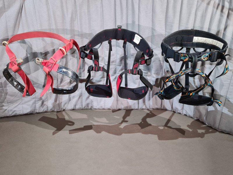
The main harness that goes around your waist, with leg loops around your legs. Unlike a belay belt, a sit harness is intended to be PPE. SRT harnesses have connection loops at both sides, held closed using a D-ring. Climbing harnesses usually have a series of belaying loops at the front, and are closed with a buckle instead of a D-ring. Canyoning harnesses usually have one or two attachment loops at the front, and are closed with a buckle instead of a D-ring. SRT harnesses usually have either a single waist belt that is relatively narrow, or two waist belts, or a waist belt and a bum strap. Climbing harnesses ussually have a much wider, padded waist belt and padded leg loops. Canyoning harnesses normally have a simple or padded waist belt and leg loops, and have a protective sheet joining the belt and leg loops. SRT harnesses are designed to be relatively comfortable for sitting in for long periods, but are not designed to take a shock load, and can be relatively uncomfortable when not seated. Climbing harnesses are designed to be comfortable when not in use, and can take a shock load, but can be uncomfortable to sit in for long periods. Climbing harnesses usually have extra straps to hold the leg loops to the back of the waist belt, while caving harnesses usually do not. The sit harness is the main load-bearing harness. The two leg loops and two connection loops intentionally provide minimal redundancy, just in case part of the harness fails.
The boatswain's chair (pronounced "bosun's chair") is a type of sit harness with a few designs, that may still be seen in limited cases, such as mountain rescue or limited show cave access. All are based on a stick, plank, or canvas strap that is sat on. None of these are standard vertical caving equipment any more, so they are covered in the history section below.
Harrow Hill, Cissbury Ring and Grime's Graves are late Neolithic flint mining sites in Britain, each with hundreds of mine shafts from 6-13 metres deep, dating from 4000-2200 BCE, 4000-3500 BCE and 2650-2300 BCE respectively (Harrow Hill has some slightly older open cast pits). The most common conjecture is that some sort of ladder might have been used for access, but there is actually no supporting evidence for ladders. There is evidence of a log being placed over the shafts (thought to be useful for running a rope over, to keep it away from the walls), and of rope rub marks seen on the passages, suggesting that the flint and waste chalk was removed by hauling. The rocks could have been tied up in individual pieces, but a basket or bag of some kind (such as leather) is thought to be more convenient and much more likely, and grooves in the passages suggest wooden sledges might have been used to pull rocks around. It would be most convenient for these sledges to double up as the basket for hauling. The most obvious means of access would have been for the miners to sit or stand on the same sledges in order to be lowered or hauled from the mines. There is no actual evidence to show whether this method was used, however, and it is purely conjecture, but if so, this would have been one of the earliest kinds of sit harness. Another alternative was that the ropes were tied directly to the miners in some way.
Some of the earliest harnesses would probably have originated with the use of a mechane (μηχανή) in Greek theatre, known as Deus ex Machina when used in Roman theatre. These were cranes situated above a stage, which could lift actors and other props as part of a performance, typically to symbolise gods or heroes, being able to lift themselves above regular people. Their earliest use is thought to be Aeschylus in 458 BCE for the play Eumenides, Sophocles for some unknown play, or Euripides in 438 BCE for the play Alcestis or 431 BCE for the play Medea. It is not known how they attached a rope to the actor, but a common conjecture is that a basket or chair was typically used for the actor to sit in or on, and this method was used for some productions such as The Clouds by Aristophanes (386 BCE). According to a series of vase paintings, Medea was performed using a chariot which the actor sat on (depicted in about 400 BCE in Italy), Stheneboea by Euripides (455-422 BCE, depicted in 400-375 BCE) had an actor on a flying Pegasus, and Carians by Aeschylus (499-456 BCE, depicted in 400-380 BCE) had actors floating in a forwards leaning position. However, it is not known when these approaches were used for each play, since the vases were made some time later, and may have used artistic license rather than accurately depicting a performance. It is most likely that ropes were normally tied around various limbs of the actor (or horse!), hidden beneath their costume, so that they could be held at whatever angle was needed. Greek military instructions written by Αἰνείας ὁ Τακτικός (Aeneas Tacticus) in about 356-346 BCE described how a person could be lowered down a castle wall in a basket, which could be made from woven reeds, according to earlier instructions. In China, the earliest known depiction of a Tyrolean traverse from 250 BCE showed what appeares to be a full body harness, made from two loops, with a single one under the buttocks, and one around the chest under the arms. It is possible that it is meant to be in two separate pieces, but it is not drawn clearly enough to tell.
The original caving sit harness was simply a boatswain's chair (or bosun's chair); a plank, stick or canvas seat tied to a rope, which a sailor or caver would sit on while someone else lowered or hauled them on the rope. Though there are many designs, there were two main designs that were used early on. The first is a stick tied to a rope as a cross bar, where the rope passes between the legs, is then tied to the stick, and the stick is used as a seat, commonly used on single-rope swings. The second is a flat plank with thinner ropes attached to the plank at each corner, or at the two ends. These ropes are joined together some distance above the plank, where they are tied to the main rope. This approach is commonly used for playground swings, but in a playground, they normally use two separate chains, instead of a single rope. These started out as an adaptation of the swing, whose history dates back to 1450-1300 BCE in what is now Greece, with Minoan ornaments from that era in Hagia Triada, Crete, clearly showing the flat plank design that would later be called a boatswain's chair. In Greek, they were called αἰώρα or ἐώρα (aióra or eóra).
Swings spread around the world, beginning with European and the Middle Eastern regions, with other artworks and writings from Greece in 540 BCE and Greek Cyrenaica (now Libya) 225-175 BCE, their first known depiction in Africa. Greeks often made them from a Δίφρος (diphros), a folding stool with tiny legs, and almost all early depictions show the legs. Romans called swings oscillum (sometimes said to be petaurus, but that involves a wheel throwing a person into the air, and that does not sound like a swing). Quintus Cornificius wrote about the use of swings during a festival in the Roman part of the Roman Republic (now Italy) and described the Roman swing legend, in about 80-50 BCE. He does not specify whether they used plank-style swings or cross bar swings or both, but people were trying to mimic ornamental discs (also called oscillum) which usually hung from a single string, so they could spin in the wind. The myth he described is nonsense, relating to the mythical Kings of Alba Longa, but the important part is that by the time he wrote it, Romans had known about swings for so long that they had forgotten their origin. (Surviving frescos from Pompeii may appear to depict the cross bar stick form, but are more likely to be a faded depiction of a woman holding a spear and shield.) Mesoamerican cultures later developed the same ideas, with artworks from 250-900 AD. They were then depicted in India around 400-500 CE, and in European artworks from 700-750 CE and 1338-1344. From India, they had spread back to sub-Saharan Africa, and onwards to Southeast Asia. Artworks depicting swings became increasingly common in most parts of Europe and Asia by the 1700s. The swing was traditionally called a meritot, meritote, totter, merry-totter or merry-trotter (with various spellings, all meaning happy oscillation) in English by the 1600s (first possibly recorded as "viritoot" - youthful oscillation - in Geoffrey Chaucer's The Miller's Tale in about 1387), escarpolette, brandilloire or the modern balançoire in French, while German already had the modern Schaukel and Italian had the modern altalena.
China deserves a special mention here. It is often claimed that China supposedly had swings from 771-476 BCE, but the evidence is severely lacking, and all relates to a lost book called 古今藝術圖 (Ancient And Modern Art Pictures), probably written between 200-500 CE by an unknown author. Others who had actually seen the book and wrote about it (the earliest being after 554 CE), said it described a local legend that swings had been introduced by the northern region's mountain barbarians. One of them quoted the original book as saying "others say that" it was a group of mountain barbarians, that had been wiped out by 齊桓公 (Duke Huan of Qi), whose battles had been around 671-656 BCE (against southern enemies), 850-1150 years earlier at the start of the iron age. Even allowing imperfect translation (it might have meant "some say that"), it is very clearly a case of "some say this, others say that", not a statement of fact. In 1893, a British historian decided the mountain barbarians were a tribe who lost such a battle in 664 BCE (recorded in Chinese historical memoirs that do not mention swings). The original book describing the swing myth's existence had no evidence whatsoever to support it, and nothing has ever been found to support it, despite ample written records from that era. It has since been lost, with other authors quoting it. Some of their writings have also been lost and the original book's contents are only known because of the game of Chinese Whispers. And yet today, the China swing myth gets repeated everywhere as if it were proven fact. It is like me writing something like "in Britain, there is a rumour that we learned about horseback polo from a Cumbric tribe who were wiped out by Saxon King Eardwulf of Northumbria" (who ruled in 796-810 CE and actually fought Vikings), with absolutely no evidence. My book is then lost. Other people quote my book saying what they think I said, but some of their books are also lost. Other people quote what their books said. In the year 3500, people treat what they think I wrote as absolute fact, and claim "we had polo in Early Medieval Britain, which was 410-1066 CE" (it is a Persian game from about 600-500 BCE, and arrived in Britain via India in 1869). It is actually scary to think how many things that people commonly state as fact are based on this level of non-evidence. The claim that swings existed in China in 771-476 BCE should be considered utter nonsense, and it is safer to say that plank-style swings existed outside of what was then the main part of China, a few generations before 200-500 CE when the first book was probably written, which is consistent with the idea spreading from the Middle East. Having initially been considered an activity for girls, it was first conclusively mentioned in a Chinese dictionary in 523 CE, and subsequently considered something mainly for women and children. Anyway, I have now digressed too far. Back to boatswain's chairs.
Their first use other than as a swing was likely to have been in the mining, fruit picking or drama industries, as a means to lower someone out of a building, or for lifting a person upwards temporarily during other leisure activities (but more on that later), but there is no known proof of which came first. Boatswain's chairs had existed in sailing for such a long time that their first usage is not recorded. They are named after a nautical job title, and it is very common to see the claim that they originated in sailing. However, there is no known evidence of their use by sailors before the 1700s (although a couple of somewhat related ideas appeared briefly in the mid 1500s), and it is clear that their use at sea was recorded much later than several other purposes. They were occasionally used almost exclusively to lift ladies on or off ships by the end of the 1700s, and earned the name "lady's chair" by the 1830s. They remained uncommon for normal work on ships until the later part of the 1800s, and do not appear in sailing dictionaries until then, with the earliest known published mention of them with the name boatswain's chair being in the Bombay Gazette from 1855, and then in a sailing book from 1858. They were also known as a boatswain's cradle from 1860, and known as a "rigger's chair" from the 1880s onwards.
In the 1070s, the Norman Bayeux Tapestry depicted Anglo-Saxon Harold Godwinson, then Earl of Wessex, sailing to Normandy in 1064 to meet William The Conqueror, then Duke of Normandy. The voyage was made using a longship, which was one of the most advanced ships of its time, used by the Anglo-Saxons, Normans and Vikings to cross oceans. A lookout sailor is shown manually climbing to the top of the (fairly thin) mast in order to see the distance better, by manually gripping the mast with hands, arms and legs. Although other sailors are shown using ropes to haul the sail up the mast using pulleys, they did not lift the lookout up the mast. If boatswain's chairs had existed in sailing at that point, they would have been using them, but they were definitely shown not doing so. Martin Bostal, Doctor of Medieval archaeology, Université de Caen Normandie and Musée de la Tapisserie de Bayeux, stated (personal communication) that he had "never found any mention of such devices in sources related to navigation during the Middle Ages", and confirmed that the tapestry shows the lookout's tunic, not a chair of any kind. No depictions are known of their use in the 1400s and 1500s, with gang planks and gangways being the main methods shown for noblemen and noblewomen to board a ship, with rope ladders used when boarding from rowing boats, and King Henry VIII being shown using a rigid ladder to climb from a rowing boat into a ship, in a painting that was made for him of the actual event. These approaches continued, including for the nobility, through the 1600s, with no known evidence for the use of boatswain's chairs, even though cranes existed at docks, and other items were hoisted onto ships on platforms that could have inspired a chair.
From Ancient Greece all the way through to the middle ages, building work seems to have used only traditional approaches of ladders and scaffolding, even when working on the tall spires of towers and churches. While winches were used extensively, they are only ever depicted lifting building materials, never people. In Roman times, scaffolding was used which could be inserted into sockets in the walls of large buildings. This approach was also used throughout the middle ages, and appears in many Medieval manuscripts depicting castle building, along with scaffolding and ladders. These sockets, in spite of providing a vulnerability that an enemy could use, are shown on the outside walls of castles, typically only near the top. However, large planks, which were called stages (now often called hanging staging), could be hung over the side of a building by ropes, potentially accessed using a ladder. Stages provided something to sit on and work from at any height, but were a lot larger than a boatswain's chair, and would have enough space for more than one person to work from at once. Because of this larger size, they typically needed two entirely separate ropes, one at each end, hanging separately from the top of the wall, and their position could not be easily adjusted while in use. They did not provide any additional safety, and both hands would normally have been needed for any work. This is something that had been in use since at least Medieval times, seen in the French manuscript Histoire ancienne jusqu'à César in 1210, and considered ancient already by that stage (since it was depicted in a Biblical scene). However, it was probably not used in Roman times, and is not known to be depicted in Roman manuals, so hanging staging probably emerged between 500 CE and 1100 CE. In fact, even though the Roman Tomb of the Haterii (100-200 CE) has a carving of a crane with some workers shown working at height, they are shown holding onto ropes and sitting on the pulleys, not using a harness of any kind.
The first confirmed use of a suspended seat as something other than a simple swing is from 14-37 CE, depicted on a tiny Roman spintria coin (spintriae are tokens depicting adult activities, that were probably used in brother tells, but their precise purpose is not known). The depiction shows what appears to be a boatswain's chair using the same approach as the plank design, with ropes from the sides that appear to join into a single rope, going to a pulley up above, and back down to a person who could raise or lower the chair, exactly like a modern boatswain's chair. The seat seems to be a small bench with a wide scroll leg, but might possibly be a basket with the person sitting on its flat lid, or be a flat surface covered in a loose piece of cloth. Its purpose is clearly visible as a sensory touch complex swing. (Early analysis from 1869 invented a second rope and removed other details, but the author was working from a very poor photograph from 1843.) The Christian Bible includes a story based in 33-36 CE, described in the Book Of Acts, most likely written around 80-90 CE, and again in the Second Epistle to the Corinthians, most likely written in 55-56 CE, where the character Saul of Tarsus (who later becomes St. Paul) is supposed to have been lowered down a wall in a basket. The original Greek texts suggest it was a woven basket, but the two times it is mentioned do not agree whether it is small or large. Whether or not it actually happened is a matter for theological debate, but what matters is that when the story was written, someone thought that a basket would be useful as a sit harness. In about 500 CE, the earliest form of merry-go-round appeared in the Byzantine Empire, in an area which is now Turkey. This had people sitting in baskets, spun around at the top of a pole.
In 559 CE, 高洋 (Gao Yang), ruler of 北齐 (Northern Qi), now part of China, executed hundreds of members of the 元 (Yuan) family, by tying increasingly complex kites to them, and throwing them off buildings. Since survival was not part of the plan, it is unlikely that harnesses of any kind were used, and it sounds like they were just tied directly to the fabric or structure of the kite, sat on top of it, or held onto a rigid bar. Most other man-lifting kite stories from China can be considered pure fantasy, not least because they often refer to deity figures rather than actual people, and were generally passed down as legend rather than written historical records. Even historical records were often heavily modified or embellished to promote the ideologies of a specific ruler, so the kite execution story may also be heavily modified. Much later attempts in other continents would use actual harnesses, at which point they become relevant here.
In 700-750 CE, a series of frescos were painted in St. Prokulus Kirche (Saint Proculus Church), Naturno, Kingdom Of The Lombards, now Italy. One of these, known as "The Saint On The Swing", shows a person being lowered through a gap in a wall, on a form of boatswain's chair (it cannot possibly make sense as an actual swing, as there was a wall in the way, and a swing would not work). The chair is probably meant to be made either from the rope itself being looped underneath him, or some fabric, but the detail is not good enough to tell. The most common interpretation is that this fresco depicts Proculus of Verona fleeing Verona, Roman Empire (now Italy), in around 290 CE, but it could also be Saul of Tarsus (though it definitely does not depict a basket). There is no record of Proculus of Verona actually fleeing the city that way, but when the frescos were painted, someone thought that a boatswain's chair made from a fabric of some kind could be used to get down a wall. This is the first version of the canvas boatswain's chair, and is the earliest known depiction of them being used for rope access purposes, an approach that would later be used by miners. The artist drew it with two separate ropes going upwards instead of joining them into a single rope, which would have made lowering someone extremely difficult, but this is likely to be due to an artistic mistake. From 1242 until 1718, the monks at Pfäfers, Holy Roman Empire (now Switzerland) would lower people 80 metres in a basket into the Taminaschlucht (Tamina Gorge), to use the Bad Pfäfers hot springs for their supposed healing qualities. They were blindfolded so they would not be too frightened. This was then replaced with a new bath outside the gorge, then a walkway was cut into the gorge. In about 1304, the Codex Manesse depicted a woman lifting her partner up to her window using a winch, with a bucket/basket instead of a harness, in Zürich, Holy Roman Empire (now Switzerland).
The Covolo di Butistone cave (known as Kofel in German) in the Brente river valley in Italy has been described since 1004 CE as being used as a fortress, situated part way up a tall cliff. Over the centuries, it has been modified heavily to add buildings and tunnels that were carved out of the rock, and to remove the holds that were originally used to access it by climbing. Most of the work is thought to have been done for the Scaligeri princes of Verona in 1321-1337, though it had changed hands several times after then (and a few times before), and any other group involved could have made changes. In most cases, it was too hard to reach to attack directly, and it was instead attacked through bombardments from the other side of the valley. It was controlled by the Holy Roman Empire (specifically Austria) from 1509 until 1797, in spite of the Republic of Venice having taken control of the countryside around it in 1511, and had its fortifications improved in 1509. For a long time, a hand powered winch was the only way to access the fortress, which had probably been installed between 1321-1337, since the space for it was provided by the early layout. The rope was described by Domenico Odorico Capra in a 1580 report to the Republic of Venice, being used to lift people 35 metres up, from within the cave, but the chair was not mentioned. The rope was mentioned in 1596 by a saboteur. It was described in 1598 by a visiting clergyman who sat on the army captain's lap to ascend to the cave "in company". The captain was described as "mounting" the thick rope (referring to a boatswain's chair), and the clergyman was tied to it, but it does not say exactly how they were arranged. According to the clergyman, the "magnificent captain" had "a cheerful face". It was described in the same year in a report by Venetian superintendant Francesco Caldogno, as "a rope sent down with a wooden seat to stay on" (using the word "seggetta", meaning a very simplistic seat or stool) to raise people "one by one". It was described as part of the fortress, where the fortress was made by "men in ancient times", suggesting that the rope and boatswain's chair were old enough by then for their origin to have already been forgotten. It was depicted in around 1610 (often mis-stated as early sixteenth century) in a painting by Matthias Burgklechner (or spelled Mathias and Burgklehner) showing a woman and child sitting on a cross bar boatswain's chair facing each other. (The painting also shows a separate rope for lifting a basket of supplies, guided by a tension traverse.) He also depicted it in an enormous map (bottom-right corner) of the Tyrolean Alps in 1611 with a person on a boatswain's chair. His visit may have been years earlier, and while the date of the painting is not precisely known (it was definitely before his death in 1642), it probably originated from the same sketch that would have presumably been used to make the map. Either way, the painting or the map are the first time a boatswain's chair is recognisably depicted as a method to access a cave.
Covolo di Butistone's boatswain's chair was mentioned as a rope in 1615. The boatswain's chair was depicted in 1625 in a painting in the G. v. Pfaundler collection. It was described as a rope in 1640-1682. It was depicted again in 1649 (reprinted in 1679 and adapted by Johann Baptist Homann in 1716) by Matthäus Merian, clearly showing someone on a boatswain's chair. The method was described in detail in 1664 by French traveller Balthasar de Monconys as being 30 metres up a 60 metre cliff (it was actually 45 metres up a 180 metre cliff), using a rope and pulley. A stick was tied to the end of the rope as a boatswain's chair, which was used as a sit harness, the first time is is clearly described as a method to access a cave. A leather strap was tied to the rope, and fastened around the body to avoid falling off. It does not say exactly how the strap was used, but does not use the word for belt, so it may have been used as a chest harness, and would make most sense that way. A much later description (decades after it stopped being used) called it a belt, however. Although the fortress was primarily used for around 30-40 soldiers, the saboteur mentioned that the captain's "women" and family lived there with him, and Balthasar de Monconys reported that men, women and small children were in the cave, and they will all have accessed it the same way. It was later used to house prisoners too. The fortress continued to be accessed this way until 1797, and was mentioned by many travel writers. By the 1800s, it could only be accessed using very long ladders instead.
In the 1300s, a Japanese drawing (later adapted into a pair of engravings) and later engravings showing designs from the same time, showed an aerial ropeway called a "野猿" ("yaen", a wild monkey), using a basket as a harness, which a person could sit or stand in. In 1338-1344 in Flanders (now Belgium), illustrator Jehan de Grise depicted children on a swing, as an unrelated decoration for the manuscript Li romans du boin roi Alixandre. The swing was made from a loop of rope, and a child sat in the bottom of the loop. While this is certainly a much older method (it is probably depicted in the earlier fresco), it is the first time it is known to be depicted as a swing. It would continue to be used for centuries as a swing, with the rope eventually widened into a strap, which is occasionally still used for both swings and boatswain's chairs today. Some time between 1388 and 1423, the Hausbücher der Nürnberger Zwölfbrüderstiftungen illustrations from Nürnberg (Nuremberg), Holy Roman Empire, now Bavaria, Germany, included an image of a person making wire. The job is not important here, but he is shown sitting on a plank-style boatswain's chair, as a seat. The same approach is used for updated depictions in 1430-1504 and 1533. None of the illustrations show them being used to work at height, even though masonry, building carpentry, roofing, and exterior decorating work are shown as late as 1669. In all cases, scaffolding and ladders are shown instead. At some point during the 1400s, merry-go-rounds were being used in the Ottoman Empire for military training, which was depicted in a manuscript somewhere in what is now Italy. The seats are shown very poorly, but the rope appears to be simply looped underneath the thighs. In 1411, in the Holy Roman Empire (now Germany), Johannes Hartlieb depicted an aerial ropeway using baskets to carry goods or people. This approach was used for centuries, eventually developing into larger and larger baskets, gondolas, and carriages, resulting in the modern cable car. In 1468, Joana (Joan or Juana) of Portugal, then queen of Castile and León (now Spain) escaped from the Castle of Alaejos by being lowered somewhat unsuccessfully in a basket, and was injured when it was dropped. In the 1470s, the earliest known depiction of a parachute used a simple belt for a harness, thought to have been drawn by Francesco di Giorgio Martini in the Republic of Siena (now Italy). (This is often stated as being by Mariano di Jacopo, also known as Taccola, but listing the date as 20 years after his death.)
In the Holy Roman Empire, now Italy, Leonardo da Vinci drew several sketches of his ornithopter aeroplane in the Codex Atlanticus. A couple of these used a minimal full body harness consisting of a single (painful) strap or rope between the legs. They had either a couple of straps around the chest, or a single hoop and shoulder supports, because toppling sideways out of it would be extremely easy otherwise. The sketch's page (click "Verso") is undated, but others of ornithopter parts are from 1480, 1480, 1480, 1483, 1485, 1488-1490, 1488-1490, 1493, 1493, 1493 and undated, and the sketches showing the harness seem to match the early ornithopter design from 1480. (Much better sketches appear to be fake modern composites, not authentic drawings.) The same codex includes a 1485 sketch of a parachute (click "Verso"), which used the same single strap or rope between the legs, and a single strap or rope around the chest, pulling the other strap close to the body, to increase stability.
A winch was used to access clifftop monasteries at Meteora in Greece, with Varlaam Monastery using a basket or net from as early as 1517. In about 1520-1530, Heinrich Cornelius Agrippa von Nettesheim (whose first name might be written as Henry or Henricus), from the Holy Roman Empire (now Germany), developed a descender. It included an iron bar, which hung below the device using two separate ropes just a few centimetres apart, and was used as a cross bar boatswain's chair. In 1522, miners in Poland were described as simply sitting in a woven loop of rope which was tied to the main rope, while they held onto the rope with their hands and one leg. They would do so in a cluster of 7 miners at once, each sitting in their own loop. This is described much more clearly in the following centuries. In 1535, a diving bell designed by Guglielmo de Lorena used a strap between the legs as a sit harness, an approach that was repeated with more straps by Franz Kessler in 1616. A preacher was lowered in a basket to escape from a walled town in Flanders (now Belgium) in 1545. In 1556, but researched from 1528-1550, the book De re metallica (on the nature of metals) listed how metal mining was carried out in the Holy Roman Empire (now Germany, Czech Republic, Austria and Italy) and Hungary (now Slovakia). It described how miners were sometimes winched down and up mine shafts "mounted on a stick or in/on a [framework]", referring to a cross bar boatswain's chair (which was depicted), though ladders were far more common. The original Latin "in crate" is ambiguous as to what kind of framework it refers to, and could mean "in an iron cage" or "on a wickerwork item" or even "wrapped up in a picket fence", but it has been translated without evidence as "on a wicker basket" in a 1950 English translation (the same translation changes numerous other parts of the text in such a way that the original details are lost).
In 1550 but written during the year before publication, polymath Gerolamo Cardano published a book called De Subtilitate Rerum (On The Subtlety/Intricacy/Finesse Of Things) in the Holy Roman Empire (now Italy). (An English translation of a later edition is available, but it gets some of the details wrong.) As well as describing Heinrich Cornelius Agrippa von Nettesheim's descender, it described two other devices. One was a simple pulley with a counterweight, which could be used to lift a person. The person sat on a stick, which was used as a cross bar boatswain's chair. The other device was a descender used by sailors, probably sailing on local rivers in the Holy Roman Empire (now Italy). His book described it as a current technique, and I have not found any earlier or later references to it. It consisted of a simple stick, which was sat on like a cross bar boatswain's chair, with the rope wrapped around it a few times between the legs, without being attached to it. While moving, it actively tried to throw the user off the stick and disconnect itself from the rope, and was extremely dangerous (described in more detail in the section on descenders). As a result, although it looked superficially like a boatswain's chair and is the first time sailors are known to have used something that could be mistaken for a boatswain's chair, it did not function as one, or even as a sit harness. The entire purpose of a sit harness is to remain properly attached to both the person and whatever device they are using, making the person safer, so that they do not have to rely on their hands to keep themselves attached to it. This device tried its hardest to fail at all of these points, and would have caused numerous fatalities if it had continued to be used.
In 1571 in Cyprus, Ottoman (Turkish) attackers displayed captured Venetian prisoner Marcantonio Bragadin in what is usually described as a chair suspended from the mast of a ship. He became a religious icon, and the story has been embelished for centuries, with details greatly modified with each re-telling. The earliest surviving English records from a year later say that it was a "chaire to leane and stay vpon" (chair to lean and stay upon). The earliest surviving records that actually give details, written in Italian by a historian over 100 years after the event, state that a "support chair" was used, which at the time was the Italian term for an armchair, not a boatswain's chair. This would mean that a literal armchair with a back and arms, and presumably legs, was tied to the rope. It was probably a wooden captain's chair. In 1591, Charles de Lorraine, Duke of Guise in France, escaped from the Château de Tours, in France. He did so by being lowered part way to the ground out of a window by servants, using a stick tied to a rope, which he "took between his legs", clearly describing a boatswain's chair. The rope was released by the servants to avoid gunfire, causing him to fall several metres and sustain injuries, but he still managed to escape.
In 1595, François de Chalvet from France reported that the locals were using "very dangerous machines" to descend 103 metres into the Gouffre de Padirac, to mine guano from the cave to make saltpeter. These would have been winches, thought to have had a boatswain's chair consisting of a wooden cross bar tied to a rope, although they may have used a basket or bucket instead. By 1600, a basket was used at St. Catherine's Monastery in Sinai, Egypt, to enter or exit the monastery. The use of a basket was confirmed in 1658 and again in 1700. The same text was repeated into the 1800s, without any further details, and later visitors did not describe the design in detail. In 1608, two children were lowered in a basket to escape from a fortress in northern France. In 1615-1616, Faust Vrančić from the Republic of Venice, now Croatia, updated Leonardo da Vinci's parachute, to use a pair of ropes between the legs to spread the pressure out (a wise move), but still used the chest loop.
Since the early days of large ships, sailors often used hanging staging, hung over the side of the ship. These were an alternative to working on the outside of a ship from a nearby rowing boat, and allowed them to reach higher up the ship. The third volume of the 1625 book series Purchas His Pilgrimes by Samuel Purchas has a chapter written by Ionas Poole about a ship's voyage to Greenland in 1612. It describes how the ship's "carpenter had hung a stage close by the water, whereon his tooles lay". The exact details of the stage are not given, but it was large enough for the carpenter and his tools, so was not a boatswain's chair. It was mentioned as if it were something common and ordinary, so this approach had obviously existed for a long time already, probably since the early 1500s. However, no earlier mention is known. A basket or net was used at St. Antony's Monastery in Egypt in 1616 (but had not been used in previous centuries). A similar approach may also have been used in many other monasteries, but without any known record of their earliest usage (the winch system at Deir Al Adhra, also known as Convent Of The Pulley, was only recorded in 1838).
In 1620, British traveller Peter Mundy described funfair rides in detail, used in a part of the Ottoman Empire in what is now Bulgaria, and included drawings. One was a very large swing with three ropes, using a triangular board to sit or stand on, where small children might be tied on, but adults were not. Another was a ferris wheel which had little seats hung from it, which children sat in. The last was a merry-go-round, which had little seats fastened along the outside of it. His drawings showed what look like either plank or canvas style seats, hanging from ropes on each side, like a modern swing. A much better painting from 1691-1695 (during the reign of Ahmed II) shows a merry-go-round being used in the Ottoman Empire (now Turkey), with plank-style seats. Other drawings from the Turkish parts of the Ottoman Empire during the same century show people sitting on boxes, in the same manner as a boatswain's chair. In 1627, the French novel Le Berger Extravagant by Charles Sorel (part of the L'Astrée series) described the use of a stick tied to the end of a rope as a boatswain's chair for a character in a play, so they could be swung above an audience. In 1628 in France, a boatswain's chair consisting of a stick tied to a rope which was passed through a pulley, was used to descend into a well, to retrieve a child who had fallen in. In 1630, French mathematicians Jean Leurechon and Claude Mydorge described how to use pulleys to allow a person to lift themselves easily, while seated on a cross bar boatswain's chair made from a stick tied to a pulley. This was described as being like playing on a swing, so this type of swing was in use in France. They called the system a rope ladder, and said that it was excellent in love and war! In 1638, grape harveseters in Persia (now Iran) were using a stick tied to a rope as a boatswain's chair sit harness, to hang from a tree. The design was very clearly stated, and was described as being something already used for a swing, which British and German readers were expected to be familiar with.
A descender made by French inventor Nicolas Grollier de Servière had a cross bar boatswain's chair at the bottom, described as "the stick". The exact date of its use is not recorded, but it is likely to have been shortly after obtaining the 1647 French translation of Galileo Galilei's book which described the first version of the descender, and definitely before his death in 1689. In 1648, Balthasar de Monconys visited the island of Chios in the Ottoman Empire (now Greece, despite being in Asia, just off the Turkish coast), and wrote about an Ottoman festival funfair which included a merry-go-round. The seats were described as being "shaped like little horses, hanging from [...] sticks" that stuck out at the top of a large pole, and were rotated around the pole by a person. This is around one century earlier than the hanging horse-shaped seats are commonly said to have been developed in Europe, and they presumably were inspired by the Ottoman cavalry training, rather than its European equivalent. In 1650, British instructions for making fireworks included the suggestion to use a cross bar boatswain's chair to sit on, in order to tension a rope which was wrapped around a firework. In 1851, Colombian priest Romualdo Cuervo was winched 115 metres down into the Hoyo del Aire surface shaft, in a basket.
During the 1650s and 1660s, the Royal Palace of Turin in the Duchy of Savoy (now Italy), had "a pulley and a swing", which were used by the Duchess to get from her bedroom to her bathroom (because walking is for peasants). Since ladies of that era were expected never to sit with a rope or anything else passing between their legs, and would not have been expected to be strong enough to hold on to a single rope swing, the seat will have been the plank type of boatswain's chair (though probably elaborately decorated), and could have had a back support. It was clearly used like an actual boatswain's chair, for lifting a person, since it had a pulley. Unfortunately, it no longer exists at the palace, so its design cannot be examined. The author who described it, British gentry clergyman Richard Lassels, had travelled by sea several times as a travel writer, and had evidently never seen any such device used on a ship by the time of writing (before 1668), as he described it as a "curious invention", rather than something familiar. It had presumably been installed for Christine Marie of France in the early 1650s. In 1656, a British captain stated that getting up into the high-sided English ships was very difficult, compared with a low-sided frigate, which would not have been the case if ropes were being used to lift people on board using some sort of platform. (These comments were, however, made about attacking a ship, rather than getting on board peacefully.) In 1656 and 1658, English dictionaries started suggesting that Roman swings used a single rope, and so would have used a stick as a cross beam. While it is certainly possible, and in fact likely, that it is very old, there is no known evidence of the use of that design from that time. In general, it seems that dictionaries would describe the design best known to their author, and state that it is what had always been used by others.
In 1660, while attempting to rescue a pigeon from a well in France, a basket was used for the pigeon, before a boatswain's chair consisting of a stick tied to a rope was used to lower a boy into the well. Due to gas in the well (almost certainly hydrogen sulphide from the disturbed sediment during recent cleaning), the boy and almost everyone who followed him to try to rescue him died. The others who descended the well (including ones who had previously done so to clean it) did so by using the rope as a handline. In 1662, British sailors were described as tying a rope around the waist in order to hoist a sailor, and did not use a boatswain's chair. In 1667, British Royal Society writer Thomas Sprat published a report that described merchants being lowered into a 9 metre deep lava cave on the flanks of Pico del Teide in Tenerife, Canary Islands, Spain, by servants. They had simply tied the rope around their waists. Some years before 1670, miners in Poland, then the Polish-Lithuanian Commonwealth, were described as simply tying a rope around themselves "as to sit in it" (so presumably just a loop of rope under the thighs) instead of using a dedicated harness of any kind. A second person sat on their lap, without any safety, during the descent of the mine shaft!
In 1676, British geologist John Beaumont fastened a rope around himself, in order to be lowered into Lamb Leer Cavern's Great Chamber as part of mining operations, presumably by tying it around his waist. In the same year, fowlers (bird catchers) in the Faroe Islands were described as tying a rope around their waist and between their legs to make a sit harness. In 1678, a French dictionary described the sailing punishments called "la cale", one involving hoisting a person and repeatedly dropping them into the water, known as "ducking" in English, and one where the person was just suspended over the water for a long time. The description clearly described what could easily have inspired the boatswain's chair in sailing, written in French as "he is made to lean on a stick which is placed between his legs; this stick is attached to a rope which goes to a pulley hung [overhead]; the criminal holds the rope to secure himself as much as possible". Later French dictionaries make it clear that the rope was attached to both ends of the stick, like a boatswain's chair. However, the stick was sat on in the wrong direction, from front to back, not side to side like a normal boatswain's chair, because the intention was for it to be uncomfortable. The seat was not given a name in any description. If actual boatswain's chairs had existed in sailing at that stage, there would have been a mention of the similarity, but there was nothing. The same punishment had been described in French in 1661, by tying a person to the rope, or enclosing them in an iron cage, so the stick variation must have been something relatively new in 1678. Some time before 1687, French traveller M. de la Martimire wrote that in order to descend into an active Norwegian mine, he and a mine officer had sat together "in a wooden vessel, compacted with iron and cords" and were lowered 91 metres by a crane. This is a very early mention of what would was probably a large barrel, being used as a bucket or kibble. In 1688, a British dictionary listed ducking as a sailing punishment, using a full body harness made by tying a rope around the waist, between the legs, and around the chest under the arms. This approach continued to be mentioned until 1727, using the exact same wording.
In 1690, the novel "The Irish Rogue" (written under a derogatory pseudonym by a presumably English author) included a description of a chair winched via a pulley up to the upper floors of a building. The chair was not described in detail, but was big enough for two people, and did not provide enough support to safely keep someone in the chair if they did not hold on. It sounds like it was meant to have legs, and could have been a short bench. In 1692, French traveller Jean Dumont described how at the Basilika Sankt Gereon in Köln (St. Gereon's Basilica in Cologne, which he mis-spelled "Chyrion"), the domed ceiling was cleaned by a man who "posts himself in a kind of box suspended in the middle of the dome by a good rope, and from there as from a swing, he flies from one end of the church to the other by means of some pulleys". In 1701, a British traveller on a French ship described the "la cale" punishments. It described the use of the seat as "putting a staff betwixt his legs, both the ends of it fasten'd to a rope that runs in a pully [...] and holds the rope in his hands, to secure and ease himself". It was described as if, to a British person, this was something new and unusual, even though the author was quite familiar with travelling by sea. The chair itself was not given a name, not even a "seat", even though the book was actually published in 1715 and again in 1720, showing that British seafaring travellers did not know about boatswain's chairs at that stage. By 1702, French sailors used a triangular arrangement of planks, known as a "triangle", which could encircle a mast, and be suspended from it, as a platform to work from. This approach continued to be mentioned until around the 1860s. The earliest known mention of a boatswain's chair in sailing is from 1710, when an injured British captain was hoisted from his ship into a rowing boat, and from that rowing boat onto another ship, in what was described only as "a chair". Since captains had more elaborate chairs in their cabins, it is possible that this was an actual chair rather than a boatswain's chair. In 1726, the novel Gulliver's Travels by Irish author Jonathan Swift described being lifted into Laputa using "a chain [...] with a seat fastened to the bottom [...] drawn up by pulleys". It was not described as having anything to do with ships, in spite of the author having written extensively about sailing (having taken several short voyages to England over the previous decades), and no sailing terms were used when describing it.
Steeplejacks are sometimes said to have used boatswain's chairs since the 1760s. However, they had already been used for several decades by then, in France. In 1723, they were described in a French dictionary as consisting of a "petite planche" (small plank) suspended from two ropes, which joined into a single rope that could hang from a knotted rope using a hook. They were specifically mentioned as being used by roofers and plumbers, especially when working on tall bell towers, one of the defining jobs of a steeplejack. Knotted ropes were mentioned as a way to climb used by roofers in 1684 without describing the technique, so the use of a boatswain's chair was probably much older too. In fact, roofers had been described as "dancing on ropes" and "holding firm at places they pass" by René Le Pays in 1664, suggesting that boatswain's chairs would have been needed then too. Several subsequent dictionaries referred to them as a "planchette" (board). The exact technique and design was described and clearly depicted for French roofers, steeplejacks and plumbers in two separate publications in 1762, showing that they climbed by standing in footloops which they attached using suspension hooks hooked above the knots of a knotted rope. When they reached the height they needed to work at, they would hang a plank-style boatswain's chair, which they called a "sellette" (saddle), from the rope using a suspension hook. The chair was made from a short plank, with a notch cut out at the front between the legs for the knotted rope to pass through, and had ropes looping from the front to back corners on each side, which passed through the attachment loop of a suspension hook without being tied to it, so the chair could tilt backwards when working on a sloping roof. Steeplejacks would throw a rope around the steeple, and hang the chair or ropes off that instead. The same method was described, using the exact same text, for the next two centuries.
The earliest properly documented record of the use of a boatswain's chair in exploratory caving is from 1723, when an unnamed farmer, monk Lazarus Schopper and butler Johann Zouhard were lowered 58 metres to the floor of Propast Macocha (Macocha Abyss) in the Czech Republic, using a boatswain's chair made from a (presumably wooden) peg that was driven through the rope. In the early 1700s, Spanish sailors also used a triangular arrangement of planks, which they called a guindola (or guindôla), to lift cargo onto ships using ropes. This appeared in sailing dictionaries as early as 1734. These were used as a harness to rescue sailors from the water as early as 1745, and were described as being meant for that purpose in 1794. This use continued until the life ring took over in the mid 1800s, and by 1890, it was something sailors no longer knew about. The name was subsequently used for boatswain's chairs. During the early 1700s, merry-go-rounds started to be made in Europe, and in order to replicate the military cavalry parades from France, they would hang a model horse from chains in the same way as the Ottoman merry-go-rounds had already done, which would be used as a seat. In 1729 in Hungary, Habsburg Monarchy (now Slovenia), traveller and mine explorer John George Keysler described how he was "buckled up in a kind of leather chair" to descend a 274 metre mine shaft, which is the earliest known mention of a canvas boatswain's chair underground. The exact design, and use of the buckles, is not described, but it sounds significantly more safe and comfortable than the Polish rope loops, despite being a very similar idea in essence. He also described how in Carniola, Habsburg Monarchy (now Slovenia), miners could optionally be lowered in a bucket to descend 256 metres into a mine, but it was much safer to use ladders.
Cucking stools (formerly trebuchets, tumbrells, scealding stools), a seat which a person was tied to for public humiliation, typically by having animal excrement ("cukk" or modern "cack") thrown at them, had been used as punishment from as early as Saxon times in Britain, especially for women. By the late 1500s, the most common approach was to dunk them in a filthy pond or river ("ducking"). By 1597, this version was renamed to a ducking stool, and the ponds used for the purpose, conveniently filled with duck excrement but that is not where the name comes from, were called ducking ponds. Most designs were an armchair made of wood or iron, so that the arms or body could be tied to the chair. The most common design fixed the chair to a see-saw, while a seemingly much later design hung the chair from one end of the see-saw by a chain or rope. In 1730, a dictionary written by British authors included the description of a ducking stool (called a cucking stool in the text) which consisted of a chair that hung from a rope. The rope ran through a pulley attached to a tree or post (such as a dockyard crane), and could be used to raise and lower the chair. This had created the same arrangement as a boatswain's chair, though presumably with a more substantial chair, and had presumably become well established as a design by that year, since no others were mentioned. From that year onwards, descriptions of ducking stools started to mention that the chair was "hung" over water, rather than being "set" over it. By 1750, British ships had clamps added to them especially for hanging stages, showing how common their use was, but neither clamps nor stages were mentioned in earlier sailing manuals. In 1758, a sailor was reported as being lifted to shore in "a cradle", due to injuries to both legs. Exact details of the cradle are not given, but his injuries would probably have prevented the use of a chair, and it is likely to have been a hammock or a box. At the time, "cradle" typically referred to a hospital bed, presumably made of wood, with sides to stop its occupant from falling out.
In 1762, boatswain's chairs (described only as a "chair") were used to bring "the most delicate ladies" on board ships, or take them off them. This seems to have been the only purpose they were used for, since ladies (or injured men) were considered unable to climb a ladder out of a small boat onto a large ship. It was described in a British publication as if it were a known practice by that year. At the same time, a sack was suggested as a makeshift harness when escaping a fire using a rope, though this was deemed intimidating for "the most tender and timorous". A wooden board placed in the bottom, and a metal ring in the top, stopped the sack from closing. In 1769, a mathematics book (published under a few different names) by British author William Emerson described the use of both a cross bar boatswain's chair made from a stick, and what was presumably a plank boatswain's chair, described as "a chair to sit in", by steeplejacks or builders working on masonry. It was described in mathematical terms, using a pulley arrangement, but the text stated that the plank version was commonly used for masonry work by that year. It does not mention this arrangement being used for sailors, in spite of discussing the use of pulleys within sailing in great detail in the following paragraph. In 1771 British geologist John Lloyd was lowered 57 metres into Eldon Hole by miners, by "fastening the rope to [his] body", presumably around his waist. In 1773, a boatswain's chair was being used to lower a guest off a ship, which was trading between Jamaica and Moldavia (now Moldova, Romania or Ukraine). The rope snapped and she drowned. The boatswain's chair was referred to in the Stamford Mercury simply as "a chair". The nationality of the sailors is not stated, but they are likely to have been from Moldavia.
In 1778, Johann Georg Krünitz described in Berlin, Prussia, Holy Roman Empire (now Germany) in the Oekonomische Encyklopädie volume 13, how mountaineers might use a boatswain's chair made from a stick tied to a rope to lower themselves, though the use of a boatswain's chair is specifically mentioned in relation to fire escapes. In 1783, an actual armchair, slung from 2 ropes, was used as part of a stair lift, for people who could not walk down stairs. Also in 1783, French inventor Louis-Sébastien Lenormand tested a parachute using a rigid sit harness that was shaped like a giant pair of Y-fronts, large enough to reach out to touch the waist band. By 1784, French sailors also used the word "triangle" for stages that were hung over the sides of ships. In 1785, French abbot Charles Carnus was lowered into Tindoul de la Vayssière, after being tied to the end of a rope. In 1786, well diggers in southern France were reported as using a bucket to sit in when being lowered into a well, though ladders were more common at the time. In 1787, miners in Poland, still the Polish-Lithuanian Commonwealth, were still described as tying a rope around themselves instead of using a dedicated harness (presumably still sitting in a loop of the rope), and sitting a second person on their lap. In the same year, a sensory touch complex swing depicted in a French book showed a basket with the bottom removed, being used as a sit harness. The rope went via a pulley above, exactly like the Roman spintria example, and several later examples used the same approach. A 1795 engraving of fowling in the Orkney Islands showed one person suspended on a cross bar boatswain's chair, and a person sitting in a basket on top of a Tyrolean traverse. In 1797, oil wells (literal wells that oil percolates into, like water in a normal well) in Burma (now Myanmar) were manually dug by miners, who were lowered into the well, since ladders were unusable because of the oil. The exact method of holding the miners was not described, but the only method mentioned to lift rubble, oil or anything else from the well was using a bucket, so it is likely they used the same bucket for lowering miners. In 1798, fire brigades in Leipzig, Holy Roman Empire (now Germany) were using load bearing belts as a harness, the earliest known mention of their use by fire brigades. Also in 1798, (presumably French) sailors used a boatswain's chair, described as a "small bench suspended by a rope", to haul a sailor and several French travellers up Pompey's Pillar in Egypt, including French architects Charles Norry, André Dutertre, Jean Constantin Protain and Jean-Baptiste Lepère, and several members of the Commission of Arts. It was not stated whether they also used it on a ship. In 1800, the British ship HMS Foudroyant docked in Sicily, and Queen Maria Carolina and her daughters were brought on board in a boatswain's chair, which was referred to as a "ladies' chair" in a book written in 1843.
In 1803, British inventor Knight Spencer developed the Marine Spencer, a slightly flexible life ring. It had a full body harness, consisting of straps over each shoulder, and a single strap between the legs, with the main life ring sitting around the waist. In 1804, British physician Joseph Mason Cox used an armchair with arms, back and legs as a sit harness, attached via ropes from each leg to a series of pulleys, to lift patients in the air and spin them around until they passed out. This was supposed to be a mental health treatment to reduce mania, and variations of the design were used for several decades. In the same year, a British naval ship docked in a Norwegian port, and allowed locals to board the ship for a visit. The visiting ladies were brought on board "in a chair", presumably referring to a boatswain's chair. In 1807, George William Manby developed a method to get a rope to a wrecked ship, so that people could safely get to shore (this idea had appeared before, but using mechanical throwers, without the required accuracy or distance). A mortar was fired from shore, towing a thin cord. This was used to pull over a thick rope which was pulled tight as a Tyrolean traverse. This did not have any form of harness for the person to hang from, so they either had to tie a rope around their waist, or hang a hammock, netting, hoop, smaller basket, or very large basket from the rope. In 1808, British inventor Henry Trengrouse improved the method, but it was not demonstrated on a ship until 1818. A thin cord was propelled from the ship using a rocket launched from a musket barrel. A seat, which was not described in detail, could be hung from pulleys running along it. Henry Trengrouse used the French name "chaise volante", meaning "flying chair". No reference was made to it being a sailor's seat, so it is unlikely that the sailors were used to using a boatswain's chair. At that stage, it was evidently only a simple seat, and a cork jacket was used for floatation if the rope sagged into the water, but this idea later developed into the breeches buoy used for marine rescue.
In 1818, miners from the Austrian Empire, formerly Poland and now Poland again, were once again described as sitting in loops of rope, though without mentioning anyone sitting on their laps. This description was used to create a depiction of the approach, showing them clustered above each other. The bowline on a bight started appearing in naval manuals in 1819, and is likely to have been used by sailors shortly before then to make a sit harness. One loop could be placed around the legs, and one around the body. In 1824, British inventor George Pocock started experimenting with man-lifting kites, after having experimented with load bearing kites previously. He flew his 12 year old daughter in a chair slung below a kite. The description of the event shows that it was a normal household wooden armchair, with a back and legs. By 1827, French exterior decorators ("le badigeonneur") were using plank-style boatswain's chairs while whitewashing buildings using the same methods as roofers had, something that was already known well enough by 1830-1835 to be used in satirical artworks, and appear in numerous depictions.
In 1828, John Cumberland's stage adaptation of James Fenimore Cooper's 1827 book The Red Rover, published as part of Cumberland's Minor Theatre, included the instruction that "a slung chair is hoisted" to bring ladies onboard a ship. In 1829, sailors were described (in a novel written by a British Royal Navy officer) as simply tying a rope around the body using a bowline, rather than using a boatswain's chair. This was stated as being the method used to haul "a lady" onto the ship, suggesting that a boatswain's chair was not standard equipment on ships at that stage. In 1931 a fictional story called "Jack The Giant" was published in Britain. It called boatswain's chairs on ships a "lady's chair", and said they were pulled up by a "whip", which is a rope passing through a single pulley overhead. In 1833, boatswain's chairs were being used to allow guest "ladies" to board a convict ship, described in the London Evening Standard in 1833 as to "sling a chair". In 1835, a fictional story published in Britain as if it were from a real diary, described a lady and her servants being hoisted onto a ship, on what was referred to as a "chair". The chair was clearly described as something non-standard, made from an actual wooden armchair, with its back cut shorter than normal, but keeping the armrests and legs, and it was pulled up using a simple pulley arrangement. This suggests that purpose made boatswain's chairs were still not something considered normal on a ship. In 1837, French explorer Stanislas Marie César Famin described Colombian Tyrolean traverses, which were used by the Colombians to cross rivers if a more substantial bridge was not available. They called them tarabite. They would hang from a hook on the rope in what was called (in French) a "mannequin", which at that time was the name of a long, narrow basket used to carry fruit and fish to market, and later depictions showed them to be large enough for several people. Alternatively, they would use what was described as "a net", which was depicted as a very loose sit harness with one strand passing between their legs, and others around their waist and upper body.
In 1841, British sailor Thomas Kisbee had supposedly invented the modern life ring, but Leonardo da Vinci had in fact already depicted a recognisably modern life ring in Codex Atlanticus in 1486, and several other versions had already been used by sailors, on many ships. Some were rigid, some were flexible. Cork was a common material used for them. Like the Marine Spencer before it, the cork was covered in water resistant canvas to make it more durable, while a modern life ring usually uses a plastic foam covered with plastic. Unlike an actual modern life ring, Thomas Kisbee's design had a pair of oversized shorts hanging in the middle of the life ring, which the user stepped into as a sit harness, instead of the Marine Spencer's straps. It was first used during his 1842-1847 voyage on the HMS Driver. It was adopted by the British RNLI rescue service in 1855 (though it is not known whether they kept the shorts). Shortly after that, it was incorporated into the George William Manby and Henry Trengrouse rescue systems to create the breeches buoy harness, including the shorts, which was hung from pulleys. The exact date of this is not known, but it was used to rescue the crew from the Tenterden in Northern England in 1866.
In 1842, two British teenage children were described in a report and depicted in a famous sketch, being winched up a deep mine shaft in Northen England using a "clatch-iron" (a bar with hooks dangling from each end to hold a large bucket) as a cross bar boatswain's chair, at which point it was known as a "clatch-harness". They sat facing each other, with the girl sitting on the boy's lap. (Incidentally, this picture was subsequently adapted many times, including an infamous version with the girl topless, intended to anger the Victorians. The modified image became part of the reason that many MPs voted for Lord Ashley's act of 1842 to ban women and children from working in coal mines, in spite of it not being real.) This method had been in use for some time, with children as young as 5 years old. In the same year, steeplejacks in New Zealand - still a British colony at that stage - were described using a boatswain's chair, showing how far their usage had spread within the industry already. By 1845, St. Catherine's Monastery had switched to a wooden cross bar boatswain's chair, though it is not known when that change was made during the previous 2 centuries. In 1845, miners and well diggers in Britain were described sitting in a bucket instead of a harness, while mountaineers were described as tying a rope around their body, and a "cradle" was described as being suitable as a harness for a fire escape. In 1845, a Scottish sailor named James Duncan Wright became known as Steeple Jack, after using kites to set up a rope ladder for climbing a church steeple. Between then and 1850, he used several methods of installing ropes on towers and chimneys, typically used kites and pull-up cords, and worked exclusively as a highly regarded steeplejack. These methods included the reintroduction of boatswain's chairs from sailing, as well as doubled rope technique and pulleys. He would often draw crowds, and would perform spectacles (such as descending at high speed) or set off fireworks. As a result, his name became associated with the work of steeplejacks, and British steeplejacks incorrectly assumed that sailors had been first to use boatswain's chairs. By 1847, Prussian fire brigades were using load bearing belts as a harness, and this spread throughout Europe as part of the uniform of organised fire brigades.
Cavers and mountaineers had traditionally used ropes tied around the body as a harness, initially just in a loop or several loops around the waist. A British team consisting of John Birkbeck, William Metcalfe, William Howson and 7 others used a fire escape belt as a harness when lowering cavers from the British Long Churn Cave into Alum Pot in 1847. They then used a large bucket with a winch for their successful second attempt to descend directly down Alum Pot in 1848. In 1848, American miners were described as standing with one foot in a loop of rope attached to a hook on the main mine shaft winch rope, when descending short mine shafts, instead of being held in any kind of safe harness. In 1858, British quarrymen at Penrhyn Slate Quarry were depicted working high up on a quarry face while seated in what appears to be a rope loop, exactly as the Polish miners had previously done. In 1860-1865, a barrel was used by James Duncan Wright in Belgium to lift a person who was afraid of heights 64 metres up an industrial chimney that needed repair. In 1861, a depiction of a horse powered mining winch in a British book showed a miner being lifted in a large bucket or kibble. In 1867, Count Murat and Mr. de Salvagnac were lowered in a large bucket or wicker basket into the Gouffre de Padirac, to retrieve the body of a murdered girl. In 1867, La Vie Souterraine documented what approaches miners were using in continental Europe, which was updated and translated to include British methods two years later. Both versions showed a large barrel called a tub being dangled from chains, connected to the main mine shaft rope, which would normally be used to lift rocks and ore from the mine. Miners were shown standing together in the barrel, or standing on the lip of the barrel, or sitting on the edge of the barrel, in order to be winched in and out of the mine. This seems to be the same idea described in 1687 in Norway, and would later develop into the mining cage used for most modern mines. In 1869, American W. F. Quinby created a human powered aeroplane (which did not actually fly) with a full body harness consisting of a metal waist belt, chest strap and shoulder straps. Functional gliders developed by others in subsequent years simply avoided using any kind of harness, and relied on the pilot leaning on a frame with their elbows or armpits, or using an actual seat. In 1873, Gustav Sundblad depicted explorers in the Partnachklamm gorge, and then in 1876, he depicted a hunter, both in the German Empire, published in Die Gartenlaube. In both cases, someone was depicted sitting on a boatswain's chair made from a stick with ropes attached at both ends. For improved safety, a loop of rope was added around the waist, attached to the main rope. In the earlier picture, two extra ropes are clearly visible passing between the legs, to prevent slipping off forwards.
In 1875, British caver Joseph Plumley was lowered into Plumley's Hole, using a full body harness made from the rope looped around his thighs and chest, an approach commonly used by miners. In 1876, French/Austrian explorer Charles Wiener explored an archaeological cave in Peru, using a boatswain's chair made from a narrow pole, suspended from separate ropes at each end. His own 1887 depiction of the event shows that he sat on it incorrectly, with the pole passing from front to back between his legs, which must have been very uncomfortable, and he needed shoulder support ropes to keep his balance. In 1877, American James Jerome van Wie created a sit harness with a belt and leg straps for his fire escape. In the same year, American Warren H. Knowlton created a sit harness with a belt and single strap between the legs (ouch). In the same year, workers building the Brooklyn Bridge in New York were described as using a boatswain's chair for working at height from the cables. By 1878, the fire brigades in the Stuttgart region of Germany were still using belts as a harness to lower men, but would use a sit harness for women or children, which consisted of several straps suspended beneath the belt, creating a seat. They would also use the full body harness made from rope loops, that miners used. In 1879, German inventor Ed. von Mengden invented a full body harness for use with the inchworm system, which included a single strap between the legs (ouch). Also in 1879, German mountaineer Carl Seitz of the German and Austrian Alpine Association climbers/mountaineers, was using fire brigade belts as a harness.
In 1880, the British Lamb Leer Cavern was rediscovered by miners Andrew Lyons and two others. Over the course of a few visits, foreman Joseph Nicholls, Andrew Lyons, other miners and some other visitors including James McMurtrie accessed the Great Chamber. A winch was installed, presumably that year, though it was not used for their initial visits, and both miners and visitors were lowered instead. To attach them to the rope, a loop was tied in the end of the rope, and put around one thigh as a leg loop. A smaller cord was tied to the rope higher up (this was not specified, but it does not work unless it is tied to the main rope), and that cord was tied in a loop under the arms. The leg loop carried most of the load, and the chest loop was used only for stability and safety. While this is a little safer than looping it under both legs, since it prevents slipping through it, it is extremely uncomfortable, and was described as "far from pleasant". In 1882, Walson Richards (a newspaper corespondent and the only non-miner), S. F. Sopwith, Thomas Wynne, James McMurtrie and his son were then lowered in a bucket using the winch, while Joseph Nicholls and Walson Richards were lowered into a chamber using the single leg loop approach. In the 1880s, fowlers in the Shetland Islands were using a simple loop tied in the end of the main rope, under their buttocks as a seat. To make it safer, they would tie a loop of rope around their waist, and around the seat loop strands, to hold them to it better, though this was certainly not as safe as a proper harness, as they could still slip through it. In 1882, an American architecture journal based in Massachusetts described how exterior decorators in Paris would use a boatswain's chair. This was described as if it were something new, as if American steeplejacks were not using it yet, but it was stated as something that might be seen on ships. It was described as the usual plank design made from wood, with an optional canvas seat on the wood to make it more comfortable.
In 1885, the German and Austrian Alpine Association were complaining that the attachment rings could fall out of the belts. In 1887, American captain Thomas Baldwin invented the first parachute harness that used fabric straps wrapped in several places around the body, which was the inspiration for later full body harnesses - these were completely overlooked by cavers and mountaineers. French caver Édouard-Alfred Martel used a boatswains chair made from a stick tied to a rope when being lowered or winched, starting from 1888 in the Grotte de Dargilan. French caver Gaston Vuillier used this approach, as a sit harness when using a winch, and for a lifeline when climbing a ladder, some time around 1889-1892. He also used a firefighter's belt to attach to a lifeline while using a winch. British cavers from the Wells Natural History and Archaeological Society used the single leg loop approach in the 1890s and early 1900s when using the winch in Lamb Leer Cavern. In 1891, American arborists were photographed being hauled up a tree on a plank-style boatswain's chair, and using it to rest in the tree. In 1894, British aviation inventor Baden Fletcher Smyth Baden-Powell used a small wicker basket as a sit harness with a man-lifting kite, which he crammed his buttocks into like a pair of sardines in a tin, in front of a cheering crowd. In the same year, Australian inventor Lawrence Hargrave used a metal bar which was sat on like a bike saddle (from front to back) with a man-lifting kite. Édouard-Alfred Martel then used the firefighter's belt, and was depicted using a full body harness made from the rope tied around his body, when descending Britain's famous Gaping Gill in 1895.
Members of the Yorkshire Ramblers' Club, including British cavers Edward Calvert, Tom Gray, Thomas Singleton Booth, Sam Cuttriss and J. A. Green, descended Gaping Gill by being lowered using a winch on a boatswain's chair down Jib Tunnel's Lateral Shaft, in 1896. The design was not specified, but when it was later set up as a formal winch, it would be a plank-style boatswain's chair, with a framework around it. A lifeline was simply tied around their waist. In 1896, some French arborists were using a safety belt. C. Wissemann recommended the use of fire service belts as a safety belt for mountaineering in 1898 in Germany/Austria. New Zealand inventor Robert Cockerell suggested a loop of rope that could be used as a seat in 1902. In 1905, steeplejacks in New York used a loop of canvas around one thigh as a sit harness. In about 1907, British caver Ernest Albert Baker used a simple loop knot (described as a bight) around his body while being lowered into Coral Cave.
In 1910, the mountaineering booklet Anwendung des Seiles published by the Bavarian section of the German Alpine Club described how belts were useful when crossing glaciers, but a ring of rope tied around the waist was the more common method. Also in 1910, Samuel F. Perkins used a plank type of boatswain's chair as a sit harness with a man-lifting kite. This quickly became the most common approach, due to their light weight, and by 1914-1918, the American military were experimenting with man-lifting kites using that approach. In 1913, Austrian inventor Johann Machek used a boatswain's chair as a sit harness for prusiking. By 1917, American arborists would use a sit harness made from a bowline on a bight, with one loop around the waist, and the other under the thighs, tied in the hemp rope that they were hanging on, part of what became known as a safety sling. French caver Léon Pérot used a leather belt to prusik in 1920, but this was not used underground. Antoine Joseph Marius "Paul Cans" Barthelemy used a boatswain's chair with leg loops to prusik up to the first platform of the Eiffel Tower in France at the start of 1921, which was created in 1920 as part of his system to paint buildings. It was almost certainly inspired by Johann Machek's design, but the leg loops were a significant advance. Arborists in France were still using safety belts during the 1920s, which were used by some British arborists since 1929, after being introduced by British arborist Denis Le Sueur. In 1926, Anwendung des Seiles stated that belts were no longer available in good enough quality, and that mountaineers should not use them.
Caving rapidly gained harnesses as SRT was developed in the Grenoble region of France, with Henri "Kiki" Brenot's team developing a full body harness somewhere between 1929 and 1944, created from existing strong belts such as those used by the local fire service. Cavers that did not have a harness would use a belt, but might also add leg loops using rope. During the 1930s (most likely), the first version of the Swiss seat emerged, which was just a figure of 8 shaped loop of rope, with one leg in either hole, and a descender which is clipped into the crossover point of the two strands. This progressed over time to become the more complex Swiss seat rope harness that is sometimes used by the military today. The first sit harness for American arborists was Karl Kuemmerling's 1932 climbing saddle design, which used leg loops and a waist belt made from rope covered with leather pads, and also had two gear loops. In 1936, Denis Le Sueur brought the American safety sling approach to British arboriculture. However, it was not until after 1945 that the idea was used widely across Britain, as most British arborists preferred not to use ropes at all, not even as a lifeline. At the same time, American arborists had proper sit harnesses, sometimes made with a single strap under both thighs, sometimes with individual leg loops.
Between 1936 and 1937, British caver Austin Wadsworth of the Wessex Cave Club, with help from Mr. Evans, a local lift manufacturer, had developed what was described as a "carriage" for a highly advanced tyrolean traverse. The carriage appears to have consisted of a wooden box with a metal frame, which hung from a pulley, likely to have been inspired by mining kibbles. The box was large enough for one person to sit inside, on what appears to be a small seat, with their feet inside the box as well. The seat is not shown, but could have been a stool or small bench inside the box. It was installed in Lamb Leer Cavern in 1937. The video of the event (which is also the earliest known video of British caving) also shows cavers from the Wessex Cave Club and British Speleological Association (now part of the British Cave Research Association) using a simple loop of rope around the waist with a lifeline, tied with what appears to be a bowline. In 1942, Anwendung des Seiles depicted a basic sit harness made from a loop of rope around the thighs, the back of which is pulled through between the legs, and used to clip things to (nothing is clipped to the front strand). A more complete full body harness made by mountaineer Ludwig Gramminger is described, with shoulder straps like a back pack, a belt, and a leg strap running from the hips, under the buttocks, passing between the thighs to the front to create an attachment point. A second attachment point is connected as a tether to the shoulder straps. The entire harness was made from webbing material. Its main purpose was for rescue (particularly of wartime flight crews whose aircraft had crashed in the mountains), where it would have a second sit harness attached to the shoulder straps, for carrying a casualty like a backpack. That harness had a fabric seat, and a webbing belt. An approach was described to create this design, without the belt, from an actual backpack, and some rope.
By 1944, French cavers were using elaborate sit harnesses for winching. The first was a wooden board version of the boatswain's chair, with ropes at each corner connected to the ends of a bar suspended from the rope, and a belt encircling them for safety. A board above protected the caver from falling debris. Another design simply connected the rope to the shoulder straps of Henri "Kiki" Brenot's harness, with a metal cone above to provide protection. These were both depicted by French caver Henry P. Guérin in 1944. Variations of these designs were still being used in the 1960s. He also depicted firefighter's belts as being commonly used for most purposes, and described how woven silk parachute belts might be used instead, and stated that leather was unsuitable, as it becomes brittle. By 1944, steeplejacks were using either a load bearing belt or a plank-style boatswain's chair as sit harnesses, or both at once, depicted by American steeplejack Laurie Young in The Ashley Book of Knots. In the same book, American sailor Clifford Warren Ashley stated that plank-style boatswain's chairs were also used by house painters, and showed their use with American arborists. A few different designs were depicted. In the construction industry, full body harnesses appeared around 1945, inspired by the parachute harnesses used by paratroopers during World War II. It is not known which type of harness French mountaineer Pierre Allain used in 1947, but a picture from that era looks like the modern Swiss seat arrangement (the version made from rope). The American military were using that approach in the 1950s. The Edil knot was used as a harness by Spanish climber Alberto Rabadá in the 1950s. Meanwhile, American sit harnesses for arborists were already being well made from cotton, leather and later nylon webbing, but for some reason, American cavers did not notice. In 1953, American caver William Franklin "Vertical Bill" Cuddington probably used a single leg loop around just one thigh, without any waist belt, with a carabiner clipped to it as a descender. The other leg was left completely unsupported, which would have been very uncomfortable. This was described by American cavers Dan Bloxsom and Cord H. Link in 1955 in The Troglodyte volume 1 number 9.
In 1955, a "St. John's Ambulance carrying sheet" was tied to the end of a rope and used as a sit harness in Longwood Hole in Britain by the Mendip Rescue Organiisation, during a rescue. The same approach was used again in Swildon's Hole in 1956 and Easterwater Cavern in 1957. In 1957, the Wessex Cave Club described the rope being looped around the waist when using a lifeline, and this was described the next year as using a bowline. In 1959, a boatswain's chair was used by the Mendip Rescue Organisation for hauling a casualty during a rescue.
In the early 1960s, British climber Tony Howard had been working on the Mark 1 then Mark 2 harnesses, which were used on the first ascent of Norway's Trollveggen (Troll Wall) in 1965. They most likely were a waist belt and buttock strap, with a central strap connecting the buttock strap and front, much like a G-string with upper and lower waist bands (ouch!). American cavers used a parachute harness to explore Mexican caves using a winch in 1960. In the same year, cavers from Austin, Texas, USA, used a plank-style boatswain's chair as a sit harness, for use with the Texas system of prusiking. In 1962, American caver Tom Perera described a boatswain's chair with leg loops, confusingly called the prusik sling, confusing it with prusik loops. American climbers were using the swami belt in the early 1960s. Initially, this was webbing tied in several loops around the waist (originally called a "bowline on a coil" when tied using a bowline), but Tom Perera wrote in 1962 that it had progressed to having loops tied around the legs as well, creating a sit harness called a swami seat. The Dülfer seat (a sit harness made from a sling looped behind your back with a carabiner clipped into the ends at the front, with one strand pulled through between the legs, and clipped into the carabiner) seems to have become popular at the same time, but may have been an earlier invention. It sometimes also got called the Swiss seat and swami seat, just to add confusion. In 1962, American Barry Palmer advanced his hang glider design, adding a seat described as a "ski lift type of seat" hanging beneath it.
British cavers from the South Wales Caving Club were using a Dülfer seat sit harness for abseiling and prusiking in 1963. They had also used a full body parachute harness for connecting a lifeline when using a ladder. Meanwhile, the Wessex Cave Club were recommending a basic belt made from 10 mm rope, tied in a reef knot. This knot is extremely dangerous for this purpose, as it can come untied with the simplest of pulls on a tail, and the suggested way to avoid that problem was to feed both tails between the strands of the rope to make them less likely to get caught. This was at the same time as stating that the marginally safer sheet bend was dangerous to use as a bend because it can come untied, and that only a single fisherman's knot was safe for joining ropes. It is actually alarming that they could not see the similarity between the problems and risks here. In 1963, American John Dickenson then adapted the swing again to make a fabric seat version of the boatswain's chair, which was used on his hang glider, and several others copied this approach. Over the next few years, wooden plank boatswain's chairs would be used instead. Variations, which added a waist belt or fabric back support to a boatswain's chair were being developed well into the 1970s, and some remain in use.
During the 1960s, load bearing webbing belts emerged for climbing, which became particularly popular with climbers in Britain. Leg loops could be added for comfort, creating a home made sit harness. Some time in the late 1960s, companies started making simplistic full body harnesses which could have been used for climbing, but these were ignored by most climbers, and never caught on with caving, since they do not normally allow the independent adjustment that most prusiking systems require. American caver Bill Barnedou suggested using military surplus parachute harnesses as a full body harness in 1965, which was used the same year for the Wisconsin system. American caver Dave Brison created the bi-sling sit harness with leg loops made from a separate sling in 1965. Commercial belts and leg loops (sold separately!) were available by 1968 from American Bill Forrest. In 1968, the Davek Harness was being sold by Derek Walford in Britain, which looked very much like a modern harness. British climbers Alan Waterhouse and Tony Howard, who had set up the company Troll, designed the Whillans Harness in the late 1960s, with Paul Seddon joining in later. This was specifically created for SRT, for use on an ascent of Annapurna South in 1970. It featured an uncomfortable single strap between the legs. In 1969, British Royal Air Force Mountain Rescue Team member Mike Stanton used a sling to make a sit harness for Cambridge University Caving Club member Steve Smith, presumably as a Dülfer seat. In 1970, Scottish born Brian Robertson started selling the Clan Robertson climbing harness in the USA. Several harnesses were still made in two pieces (separate belt and sit harness), or remained as just a waist belt until the 1980s.
In 1971, British cavers had used either the Whillans Harness or home made sit harnesses during the expedition to Ghar Parau in Iran, and stated that the home made ones coped with abrasion better. In the same year, British Descent magazine issue 19 showed how to make a sit harness from a sling. At the start of the 1970s, French cavers were using sit harnesses tied from webbing straps. Hang gliders developed the forwards leaning harness in 1971, beginning with a simple strap around the waist or thighs, with the earliest known use by American Dick Eipper. These quickly progressed to more complex arrangements by 1974, including the knee hanger harness made in Britain by Miles Handley, which is a full body harness with separate knee loops instead of leg loops. Around 1972, some American hang glider pilots were using individual leg loops instead of a single seat. In 1972, Nick Reckert wrote about methods and equipment for potholing, in the Cambridge University Caving Club journal. He stated that a sit harness made from a sling is better than a belt or "leg loop" (without clarifying if that was a loop for one or two legs). In 1974, French cavers were using a sit harness made from two straps with attachment points at the ends. One would be wrapped around the waist, and the other would be wrapped behind both legs, with the middle pulled through to the front. The middle and all four strap ends would be connected to the D-ring. Cavers in America were using a wide variety of home made harnesses made from webbing during the 1970s, which were surprisingly high quality. The Davison System was a full body harness with leg loops, waist belt and shoulder strap created by American Don Davison in 1974. The seat sling was created by American Will Howie in 1975, which used the Dülfer seat arrangement. American Bruce W. Smith described a Gibbs harness with leg loops and waist belt in 1976. The butt strap full body harness was created by Americans Mike Fishesser and Roger Stephens in 1977, which had leg loops, a waist belt and shoulder strap. This approach continued well into the 1980s, with many further designs. Caving and mountaineering harnesses became commercially available from Petzl in 1977, followed by the Avanti which was dedicated to just caving in 1982, both of which are modern designs of harness. European cavers almost exclusively used commercially manufactured harnesses once these became available. The full body climbing harness appeared again in 1977, from Petzl.
This history section only covers sit harnesses. This article also has a detailed history of many of the other devices and techniques that are used for vertical caving.
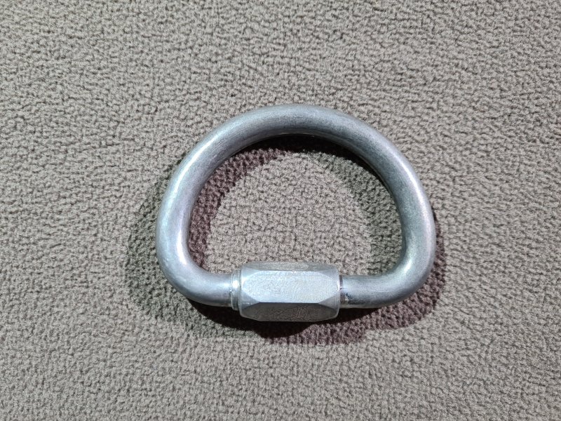
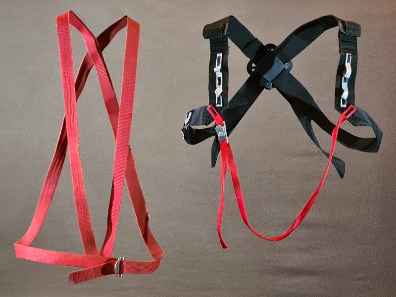

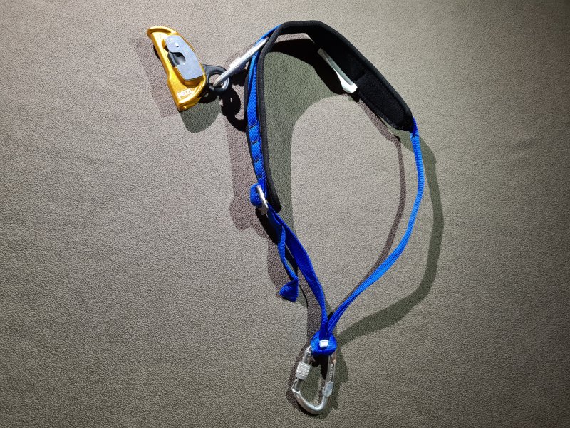
Adjustable harness or straps on your chest/shoulders, which is used only for prusiking. A chest harness is used for all prusiking systems, but can serve different purposes depending on the prusiking system, so some designs will only work in certain systems. With the frog system, the singe system, the inchworm system, and when using the another prusiking system with a chest jammer, this is used to pull the top of the chest jammer upwards, so that the rope passes through it cleanly. Kept tight when prusiking. Kept loose when not prusiking. In these systems, it is not essential for safety, and mainly helps to keep prusiking efficient. With rope walking, the Mitchell system, and when using a chest roller with the another prusiking system, this is used to hold the chest roller close to the chest, and is essential for support. With rope walking and the another prusiking system when using a floating cam, this is also used to pull bungee cord upwards. With the three Gibbs ropewalker variation of rope walking, and the pygmy system, this needs to hold the shoulder jammer close to the sholder, and is essential for safety and support. With the Gérard Alpine technique, this is used to connect the chest prusik loop, and is essential for safety. With the Plummer system and the hands and feet system, this is normally used to connect to the top jammer, and is essential for safety, and normally also support in the Plummer system. With the Texas system, the safety cord of the top jammer is often passed through a carabiner that is clipped to the chest harness to try to pull the body a little closer to the rope, where it is optional for efficiency. This is the same for the Plummer system if the top jammer's safety cord is connected that way. With the Jumar system, the footloops are passed through a carabiner clipped to the chest harness, in order to avoid falling backwards. In both cases, the chest harness needs to pull the carabiner close to the chest, and is essential for support.
Several different designs, including a dedicated chest harnesses, neck loops, sashes, wrap-around straps and figure of 8 straps. Most designs are not intended to be load bearing, since their purpose is provide stability and to hold other equipment in the correct positions, rather than to support the weight of the user. However, when using a chest roller, when using a shoulder jammer, with the Gérard Alpine technique or the Jumar system, the chest harness can be required to support heavier loads while pulling tightly towards the chest, so a more sturdy harness may be used. For chest rollers, the chest harness normally needs to be a strong, wide belt wrapped fairly tightly around the chest, with some shoulder straps to hold it in place.
The most commonly suggested version for use with a shoulder jammer is a Howie belt ("shoulder strap" in the USA). This consists of a wide webbing belt or strap which is connected to the D-ring or front of the sit harness, runs under one armpit and up the back to the opposite shoulder, then back down the front to the D-ring or sit harness again. On the shoulder, a thinner webbing loop is sewn to the Howie belt, which is tied or permanently sewn to the shoulder jammer. The Howie belt should normally have an adjustable buckle on the back and front, or use some other approach so that the length of either side can be adjusted. The one on the front allows it to be looser while not in use, since it can feel like it is trapping the neck and back in an uncomfortable way. The one on the back alters the position of the shoulder jammer on the shoulder. A Howie belt has to be strong enough that it can replace the need for a safety cord. Traditionally, they would be home made, using very strong buckles, such as a sliding bar buckle. If connected to the D-ring, they would have sewn loops at each end. If the sit harness were also home made, then the Howie Belt could just be sewn directly to it. Home made load bearing harnesses cannot be PPE rated, and their working load limit cannot be known. While there are many PPE rated chest harnesses made for rope access work, these almost never have load bearing attachment points on the correct part of the shoulder straps, and instead have one on the back and front, which is not helpful.
In China, the earliest known depiction of a Tyrolean traverse from 250 BCE showed a loop of rope around the chest as part of the harness. In 1664, personnel and their children in the Covolo di Butistone cave and fortress in the Republic of Venice, now Italy, used a leather strap to prevent them from falling off if they let go of the rope. It was not described as a belt so may have been worn as a chest harness. It may have been used that way for centuries. Mountaineers would originally have used a loop of rope tied around the waist, which would have pulled up under the armpits during a fall, so their support would have been around the chest. In 1875, British caver Joseph Plumley was lowered into Plumley's Hole, using a full body harness made from the rope looped around his thighs and chest, an approach commonly used by miners. In 1876, French/Austrian explorer Charles Wiener explored an archaeological cave in Peru, and used separate ropes to each shoulder for safety. In 1878, German inventor Ed. von Mengden described using a rope looped around the chest as a safety harness, as part of the hands and feet system for climbing telegraph poles. In 1879, this had advanced to being a chest harness, and a separate configuration using a full body harness, with its main component being a chest harness. In 1880, the British Lamb Leer Cavern was rediscovered by miners Andrew Lyons and two others, and several miners and guests were lowered into it. In addition to an extremely basic sit harness, a smaller cord was tied to the rope higher up (this was not specified, but it does not work unless it is tied to the main rope), and that cord was tied in a loop under the arms. The first dedicated climbing chest harness was made in the 1880s by Dutch mountaineer Jeanne Immink, and while the details of its design were not recorded, it seems to have consisted of straps over the shoulders and around the chest. French caver Gaston Vuillier used a shoulder strap called a saltire to loop around the rope used for lowering manually or with a winch, to provide more support, some time around 1889-1892. French caver Édouard-Alfred Martel then used this technique. Cavers from the Wells Natural History and Archaeological Society in the Mendip region of Britain also used that technique in the 1890s and early 1900s when using a winch in Lamb Leer Cavern, described as "a belt around the shoulders and round the rope".
In 1907, the mountaineering booklet Anwendung des Seiles published by the Bavarian section of the German Alpine Club, depicted a chest harness made from a rope tied into a loop using an overhand on a bight, then divided it into two loops using an overhand on a bight tied in the middle of it. The first loop went around the chest, and the second was worn over one shoulder as a saltire, with the two loops joined by a knot under the opposite arm. Only the chest loop was used for support, the saltire stopped the chest loop from falling down. Antoine Joseph Marius "Paul Cans" Barthelemy used a chest harness as part of his invention to paint buildings, which consisted of a chest belt and shoulder straps. It was first demonstrated by prusiking up to the first platform of the Eiffel Tower in France at the start of 1921, but was developed in 1920. In 1922, Anwendung des Seiles described how a bunny ears version of the overhand on a bight could be used to make the chest loop and shoulder saltire. The knot can capsize into a configuration where the loops can more easily change length, allowing the saltire to tighten during use, and would have been a liability. The next approach was to take the loop of rope that was originally tied around the waist but had been lifted up to the armpits, and force it to stay in that position by adding another loop of rope that went around the head, tucked under the chest loop at the front and back. This was proposed by Austrian mountaineer Karl Prusik in 1931. Henri "Kiki" Brenot's team developed a full body harness in the Grenoble region of France somewhere between 1929 and 1944. This included shoulder straps that were very similar to braces. Chest harnesses remained the main type of support used in mountaineering for several more decades. During the 1930s, Austrian mountaineer Raimund Schinko developed a load bearing harness. American cavers Cord H. Link and Dan Bloxsom added shoulder straps to a chest loop in 1955, described in The Troglodyte volume 1 number 9. In 1942, Anwendung des Seiles described how a an incomplete bunny ears overhand on a bight could be used to make the chest loop and shoulder saltire, with two loops going around the chest. This would have allowed the saltire to easily shorten during use, more than the original configuration, and could have potentially resulted in strangulation!
Adolph Jüsi and Walter Marti from Switzerland developed a method to wrap a sling around the chest as a chest harness in 1958, which was suggested for use with the Jumar system, which is still the basic method used for webbing harnesses today. German company Edelmann & Ridder (EDELRID) released a commercial chest harness made of rope in 1961. Several other companies released load bearing chest harnesses during the 1960s, typically made in the same way, but British company Moac made a webbing version in the mid 1960s that could alternatively be used as just a belt. Other companies also started to make webbing strap chest harnesses in the 1960s. In 1963, the Parisienne baudrier was depicted in the British Wessex Cave Club journal (identified as a baudreier Alpin) made from a sling looped around one arm, behind the back, then under the other arm, with the two ends clipped together with a carabiner on the chest. This was used to avoid falling upside down when falling off a ladder and being caught by a lifeline. During the 1970s, cavers experimented with several different types of chest harnesses for the different prusiking systems, with some being manufactured for arborists. American caver Charles Gibbs and Cleveland Grotto members including Warwick Doll and Lee Watson developed the basic Howie belt approach some time around 1966, even though in Britain it is named after American caver Will Howie. These developed into the multitude of designs that are in use today.
This history section only covers chest harnesses. This article also has a detailed history of many of the other devices and techniques that are used for vertical caving.
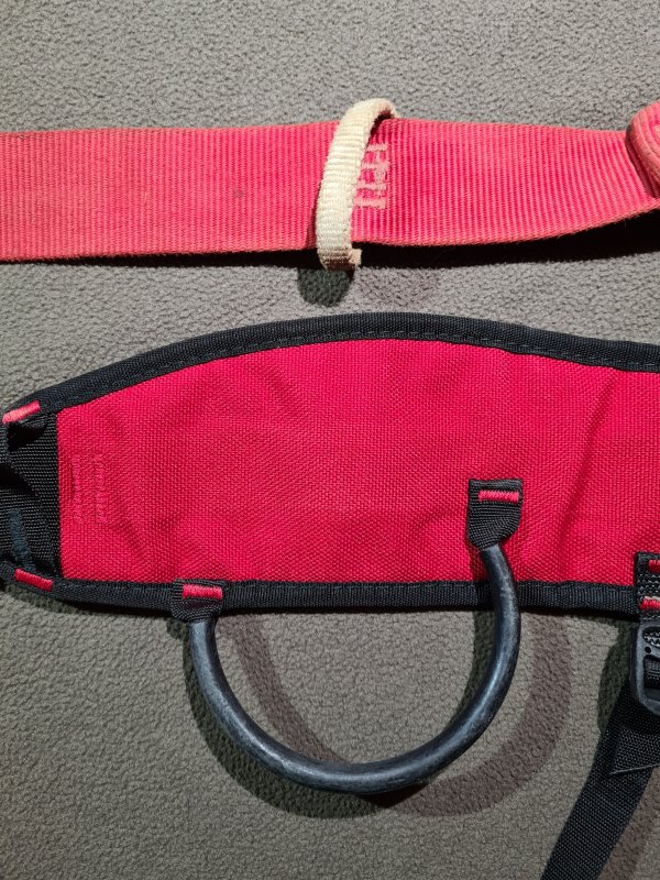
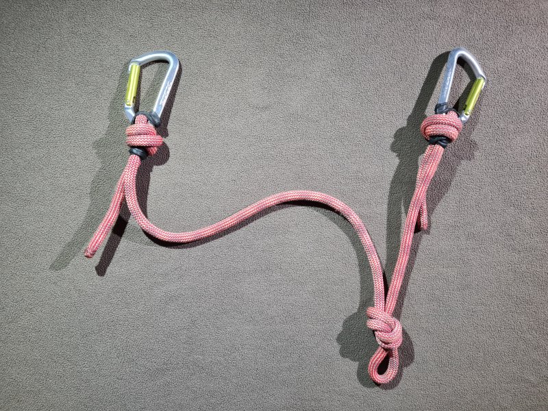
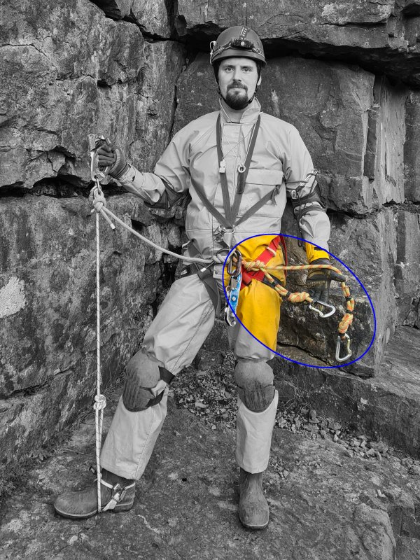
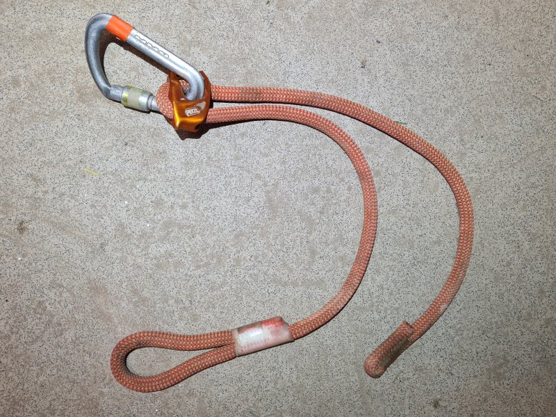
Two short tethers made from rope (typically dynamic), one "long" and one "short" that attach to your D-ring or belay belt. Each cows tail has a carabiner at the end, which can be used to attach you temporarily to anything. Normally uses snap-link (non-locking) carabiners, with either straight or bent gates, but some cavers choose to use locking carabiners. It is normal to have a "short" and a "long" cows tail. There are common lengths based on the size of the person using them. When connected to a D-ring, the short cows tail should have the tip of its carabiner hanging in front of your knee and be able to reach up to your chest. This is roughly as long as from your elbow to the start of your fingers. When connected to a D-ring, the long cows tail should have its entire carabiner hanging in front of the middle of your shin. It should be short enough that you can still reach whatever it is clipped into when hanging on it, but long enough that it is above your head when hanging on it. However, in some countries, particuarly France, it is common for cavers to have only a single cows tail, and to use the safety cord as an additional cows tail when needed.
Vital equipment for traverses, as well as passing Y-hangs and rebelays. Wherever possible, they should be clipped to ropes rather than anchors, carabiners or maillons, to avoid accidental opening of their carabiner. Some cavers connect them to the D-ring via a carabiner, to allow the cows tails to be removed when needed. Some designs have a small loop at the D-ring, which serves as a load bearing gear loop. Some dedicated designs allow cows tails to be adjusted, such as the Petzl Progress Adjust-Y. Others allow the cows tails to elongate when subjected to a sudden load, to provide additional shock absorbtion, such as the Kong Kisa, or Petzl Scorpio Vertigo. These are absolutely vital for via ferrata mountain climbing routes, but not really used much in caves. However, they would be needed if via ferrata techniques have been used in a cave (extremely uncommon).
Mountaineers and early cavers often carried rope attached to their belts or tied around their waists, which could be used to tie to objects for safety. Fire brigades used a tether attached to their belt in exactly the same way as a cows tail, even using a carabiner on the end, which could be cliped to a ladder. This was mentioned as early as 1847 in Berlin, Prussia (now Germany), where the carabiner was attached directly to the belt. However, it soon became a tether, which can be seen in 1880. French arborists were using tethers connected using carabiners in 1896 in much the same way as cavers would end up using cows tails much later. Carabiners were used by cavers to quickly connect to ropes or anchors since around the 1930s, with French caver Robert de Joly first adopting the idea of a cows tail somewhere between 1934 and 1944. Originally, the short cows tail was just a carabiner clipped directly to an attachment point on the belt, and the long cows tail was anywhere between 30 cm and 2 m in length. The short cows tail would also be used as the main attachment point, which would be connected directly to a lifeline or descender. French cavers then largely forgot about cows tails, and they almost fell out of use. However, the use of spits in 1961-1965 in France enabled pitches to be split into multiple hangs, and some French cavers started to use a single cows tail again. Cows tails were not used with indestructible rope technique, so American cavers did not initially use them, but British cavers were using a single cows tail in 1963 (or perhaps as early as 1951 for traverse lines in South Wales), and French cavers still used a single cows tail in 1973, at which point they became quite popular in France. Australian cavers started to use a single cows tail shortly before 1977, but only in specific cases where it was needed, not as a standard part of their SRT gear. The more common lengths used now were established as Alpine rigging became more advanced in the later 1970s. By 1980, British cavers were starting to use two cows tails, one long and one short. American cavers started to use them as Alpine rigging spread into America during the 1990s.
This history section only covers cows tails. This article also has a detailed history of many of the other devices and techniques that are used for vertical caving.
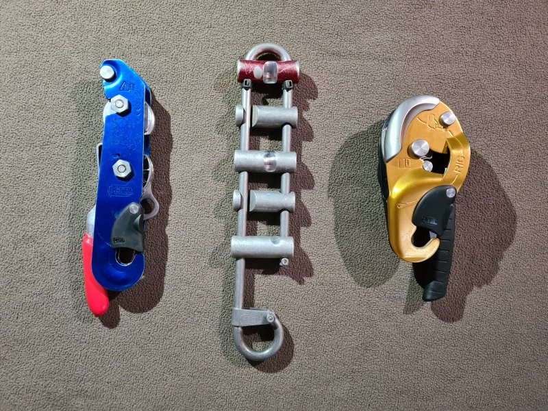
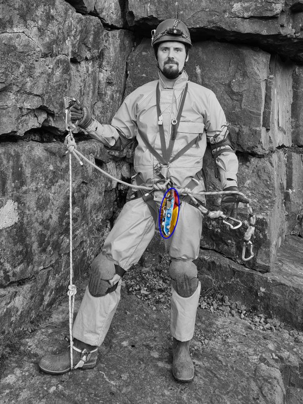
The device used to abseil. These rely on friction to control speed. The user can alter the friction and weight of the down rope in their hand, in order to alter the speed as needed. Descenders are usually connected to the D-ring via a carabiner. Caving descenders are designed to cope with muddy ropes, and do not need to be removed from their carabiner in order to connect or disconnect the rope. Climbing belay devices can almost always be used as a descender, but many designs normally cause twists in the rope, and most have relatively poor heat dissipation, which can be problematic on long abseils. Many need to be removed from their carabiner in order to connect or disconnect them from the rope, which risks dropping them while performing manoeuvres, and keeper cords are needed for them. Most (such as a Petzl GriGri) are not designed to cope with muddy ropes, and can be damaged or blocked up, preventing their adjustment mechanisms from working.
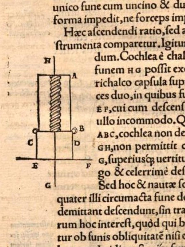
Early devices are likely to have relied on twisting the rope a few times around a rod, spool or ring, sometimes with ridges to guide the rope into specific locations. In 1550, polymath Gerolamo Cardano published a book called De Subtilitate Rerum (On The Subtlety/Intricacy/Finesse Of Things) in the Holy Roman Empire (now Italy), which included details of two descenders. (An English translation of a later edition is available, but it gets some of the details wrong.) The first of these, he attributed to Heinrich Cornelius Agrippa von Nettesheim (whose first name might be written as Henry or Henricus), from the Holy Roman Empire (now Germany). It fed the rope through a steel tube about 10 cm long, with a slight helical twist, not as extreme as a corkscrew (the diagrams show a groove like a screw thread, which would not have actually worked the way it was described, and is likely to be a mistake by the illustrators). This was surrounded by a brass casing, with two attachment points at the bottom, with short ropes that were attached to a boatswain's chair sit harness. The down rope could be pulled downwards to increase the friction (which would not have worked with a screw thread groove), or the device could be pulled towards the body in such a way that it bends the down rope. Pulling the down rope towards the body then pulling it up the side of the device would stop the motion completely. The date of its creation is not specified, but it was probably 1520-1530, when Heinrich Cornelius Agrippa von Nettesheim was adding details of how to cast metals to his book series De Occulta Philosophia, and definitely before his death in 1535. Its use was not stated, but Heinrich Cornelius Agrippa von Nettesheim had recently finished a career in the Spanish and Holy Roman Empire militaries (1508-1515). He was an academic lecturer from 1509 to 1519 and continued with academic research afterwards in many parts of the Holy Roman Empire, and was established as a polymath, well known for having a great interest in science, mechanics, natural magic, alchemy and philosophy. He likely researched it out of curiosity, believing it to have some use for rope access. Knowledge of it, however, seemed to remain entirely within academic circles, and it was not described as being used anywhere. Gerolamo Cardano stated that he had seen and held the actual devices, so they were not just theoretical.
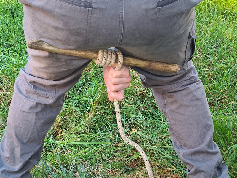
The second descender described by Gerolamo Cardano was in use by sailors, probably sailing on local rivers in the Holy Roman Empire (now Italy). His book, which was actually written in 1549-1550, described it as a current technique, and I have not found any earlier or later references to it. The sailors would take a stick wide enough to sit on, wrap the rope around it 3-4 times, then sit on the stick as a boatswain's chair. By holding the down rope, they could alter the friction, but this was extremely clumsy, as it was below their body, between their legs, and would only be usable when held upwards. The fact that the up rope was on one side of the stick and the down rope was on the other side, caused the stick to tilt dangerously. The stick needed to generate more friction from the buttocks or legs than from the rope, or it would rotate uncontrollably, friction burning the legs, and the rope would rapidly walk off the end of the stick (which it did every time during testing for the photograph). Testing showed that the up-rope needed to be on the body side of the stick, in order to not have it roll down the legs, where control would be lost even more easily. Both of these issues could easily cause inexperienced users to fall off, and as a result, this method never caught on. It was probably just used by one ship's crew, experimentally or for entertainment, and is unlikely to have been standard practice. It is an utterly terrible idea for a descender, and was quickly dismissed by Gerolamo Cardano as being too dangerous.
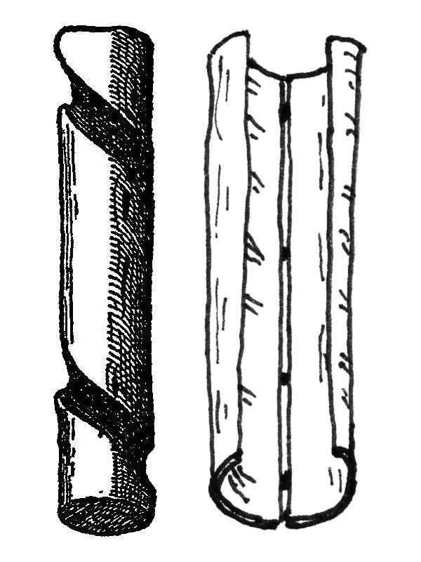
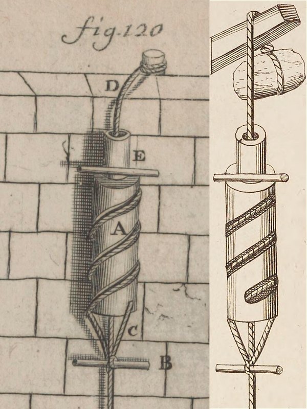
One of the earliest known descenders was described by polymath Galileo Galilei in 1638 in the Republic of Florence, Holy Roman Empire (now Italy), as something created by another (probably fictional) young Italian, to get down from a window without getting the rope burns that he got the first time. Which he needed to do more than once. For reasons. It consisted of a wooden cylinder with a spiral groove carved into it, which the rope spiralled around. To keep the rope in the groove, a sleeve made from wood or tin was wrapped around it. By gripping the sleeve, the pressure on the rope could be adjusted to control the speed. This descender was then adapted by French inventor Nicolas Grollier de Servière. The new version had a handle and rope guide at the top, and attachment ropes holding a boatswain's chair as a sit harness at the bottom. The idea of holding the lower rope to increase the friction was mentioned, and the descender's sleeve was therefore deemed pointless. The exact date of this change is not recorded, but it is likely to have been shortly after obtaining the 1647 French translation of Galileo Galilei's book, and definitely before his death in 1689. Its purpose was to descend a castle wall during an invasion. The Galileo Galilei descender was updated again in 1725 by German engineer Jacob Leupold from the Holy Roman Empire (now Germany), to correctly guide the rope as it left the bottom of the descender. Jacob Leupold suggested that it could be used as a fire escape descender. The updated version appeared in Oekonomische Encyklopädie volume 13 (page 82 and appendix) by Johann Georg Krünitz, in 1778 in Berlin, Prussia, Holy Roman Empire (now Germany), and this caused it to inspire many future fire brigade descenders.
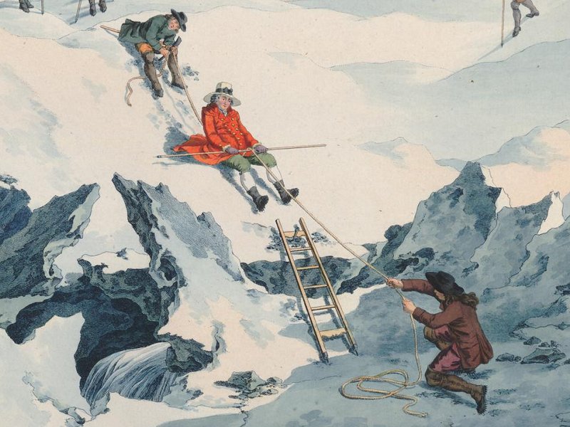
In 1787, Genevan mountaineer Horace Bénédict de Saussure used a walking pole as a descender, while descending from Mont Blanc in the French Alps. With the rope fastened to an ice axe and held by assistants at each end, he sat on the rope facing downhill, pulled it up between his legs, and looped it over a walking pole held across his thighs. The friction could be adjusted by lifting the pole, or by his assistant pulling on the down rope. Basically, this was a descender, where the level of friction was controlled by the rope running between his buttocks. Perhaps less comfortable than some other methods, but at least it would have warmed nature's pocket. As an additional benefit, it features an automatic braking system that reacts to how tightly you clench when frightened by the speed. He tried to have the depiction of this suppressed as he felt it was unflattering, and had it replaced with one where he was walking (and much younger), not realising that he had in fact made history by being the first known mountaineer to use a descender.
In 1851, fire brigades in Ulm, German Confederation (now Germany) were using a ring attached to their belt as a descender, by wrapping the rope through it twice. This approach had spread to fire brigades in Austria, Austo-Hungarian Empire, by 1872, though they would wrap it three times. This idea is what developed into a carabiner wrap. By 1877, a variation had appeared in Ulm, where the rope went through the ring, around the body, then back through the ring.
There are countless examples of descenders from the late 1800s, which were intended to be used as fire escapes, the vast majority of which can be seen in USA patents. This is mainly because the American patent system allowed any tiny change to be patented, while patents in other countries normally require more significant changes. Many inventions from other countries simply never got patented, even though they were used, and evidence of them can only be found in occasional books, newspapers and magazine adverts. (Also, many other countries have not released full details of their patents yet, with only summaries available in some cases, giving no details of the designs.) The first known fire escape descender to be properly documented was created by American Albin Warth in 1860, which worked by twisting the rope through a tube, just like the descender described by Heinrich Cornelius Agrippa von Nettesheim 3 centuries earlier.
This idea appeared again in 1871, 1871, 1877, 1877, 1877, 1878, 1883, 1883, 1884, 1909 in France, 1887, 1893.
Also in 1860, a design by American James Hobbs worked by wrapping the rope around several friction bars, with a handle for adjusting the friction.
This idea appeared again in an unknown year in Germany (but some years before 1877), 1871 in Britain, 1872, 1876 in France, 1876 in Germany twice, 1877 in Germany, 1877, 1877, 1877 in Canada, 1882, 1882, 1883, 1883, 1883, 1883, 1883, 1884, 1884, 1885, 1885, 1887, 1888, 1888, 1890, 1891, 1891, 1898 and 1904 in Germany.
In 1865, German fire brigades used an Archimedian scroll descender which operated on exactly the same principle as the Simple, with the two bobbins attached directly to a waist belt side by side instead of above each other. The friction was said to be fairly low, and the rope needed to be prepared using rosin to make it grip more once the bobbins wore down, but this is probably because of the orientation of the bobbins, and because they did not expect speed to be controlled with a hand. American E. K. Graves made a design in 1878 that used the same principle as the Simple, but with two extra bends that the rope had to twist around. This idea was clearly derived from the approach used by James Hobbs.
American Oscar F. Davis then changed the orientation to remove the extra corners and match the Simple in 1882, and added a lever to adjust the friction.
American John A. Griswold made a lever cam design in 1870, that allowed the friction to be adjusted.
This idea appeared again in 1871, 1873, 1877 in France, 1877, 1877, 1882, 1882, 1883, 1883, 1883 in Canada, 1884, 1884, 1884, 1884, 1884, 1884, 1885, 1887, 1887, 1888, 1888, 1888, 1888, 1888, 1889 and 1903 in Australia.
American George A. England made a design that twisted the rope through a series of holes in 1871.
This idea appeared again in 1876 in France, 1878, 1883, 1883, 1884, 1888, 1890, 1904 in Belgium and 1904 in Germany.
Americans W. M. Harrison and H. T. Seeley made a design that wrapped the rope several times around a spool or rod (like the future rappel log) in 1872. This is clearly very similar to what sailors were using 3 centuries earlier, but with the major benefit that the spool could not accidentally spin, and the rope could not walk off the end.
This idea appeared again in 1873, 1874 in Canada, 1876 in France twice, 1876 in Germany, 1877, 1877, 1882, 1883, 1883, 1883, 1883, 1883, 1883, 1883, 1884, 1884, 1884, 1884, 1885, 1885, 1887, 1887, 1887 and 1889 (virtually identical to one of the 1933 models).
American Hammond Marshall created a design that clamped the rope through a gap, in 1872.
This idea appeared again in 1878 in France, 1878, 1883, 1883, just using strength in 1885, 1885 and 1890.
American Thomas P. Forsyth created a device that functioned like gripping pliers in 1874.
French inventor Frederic Holthausen created a spiral descender in 1876 (the Descenseur à Spirale or Sauveteur à Spirale), which worked in almost exactly the same way as the design discribed by Galileo Galilei, though without being able to squeeze the case to regulate the speed. His French company was selling them for the fire service in 1876 and 1899, and they continued to be made by different companies for the next 100 years; not bad for such an old design. Also in 1876, Mr. Martin from France created a similar design where the sleeve could be rotated to adjust the number of turns during use.
This idea appeared again in 1877 in Austria.
A Belgian inventor created a device that functioned exactly like a rack, which was presented at an international rescue conference in 1876. The number of bars could not be changed during use, and it could only be threaded on to the start of the rope. By the next year, these were being sold by German fire brigade suppliers from southern parts of the German Empire (now Germany).
This idea appeared again in 1877 in Germany, 1877 in USA, 1877 in USA, 1884 in Canada, 1886 in Germany, 1887 in Germany and 1890 in USA.
Several approaches were based entirely on slowing down a pulley that the rope ran over. Some ran a wooden block against the pulley, some gripped the pulley's axle, and one used pressure between two pulleys. American Edward W. Averell created a design that trapped the rope at an angle between two pulleys, with a piston slowing one of them to control the speed, in 1877.
American J. Broughton combined a clamp and spool in 1877. By 1877, fire brigades in Austria, Austro-Hungarian Empire, were wrapping the rope through a carabiner several times, known as a carabiner wrap, to lower someone. By 1878, fire brigades in Stuttgart, German Empire (now Germany) were using carabiners as a descender to abseil, using a carabiner wrap, something still used in military abseiling today. This is a logical progression from the previous belt ring, but better carabiners made it safe to do so with a carabiner instead.
American J. Amess combined pliers and friction bars in 1878. In 1878, the French Navy published details of the descenders that were available for maritime usage, and all of them were fire escape descenders. None had been developed for sailing. No examples could be found in the British National Maritime Museum's extensive collections, suggesting that in spite of how much time sailors spent working with ropes, they had never previously used descenders, with the exception of their shoes. A carabiner with an integrated pulley and braking lever was designed in 1882 by the German Lohner brothers, made for the fire brigades. It would automatically add friction when released, and reduce friction when a lever was pulled. This was described as being used either as a descender, or for lowering people, the way a modern Petzl GriGri is. The inventors complained about the pulleys falling off existing designs (which were not integrated within a carabiner), which seemed to also have a similar lever. No existing devices were described in a comprehensive manual from that region 5 years earlier. American Ray Howland created a design that used a second rope to create friction against the main rope in 1883 (a very bad idea, since it could easily burn through from the friction, though hemp would cope with this a little better than nylon). American Daniel Luscher created a design that relied on bending the rope between two bobbins in 1883. This idea would never have worked the way it was described, because it can only function if there is a very heavy weight on the down rope. However, it should be noted that this is exactly the approach that can be used to descend a loaded rope with a Simple or Stop to reach a casualty, as part of an improvised rescue. Americans Charles M. Travis and Casper H. Stibolt created a design in 1883 that was little more than a rubber grip which could be squeezed around the rope, instead of holding it directly in the hands, reducing the likelihood of injury. This is really no better than a pair of gloves, and still risked losing strength and falling. Americans Joel Conover and Frank Conrick created a design that trapped the rope between two bars in 1887. American Ernst Bovensiep created a spool design where the diameter of the spool could be adjusted, creating friction where the rope rubbed against the sprung sides of the casing, in 1888. The rapid proliferation of fire escape descenders calmed down after 1891, perhaps because the patent office finally realised that the designs were largely copying each other, but also largely because of steadily improving American fire escape regulations which allowed cities to mandate better fire escapes. By 1901, New York required external stairways on housing blocks, rather than ropes, and other cities soon followed.
In 1893, Swedish inventor Anders Wilhelm Lewin created a rope grabbing device that also featured a descent lever, so it could be used as both an ascender and descender. In 1897, Austrian inventor Zdzislaw Szpor created a dedicated belay device for self belaying, for use with rope access, in the Austro-Hungarian Empire, now Poland. The device was incredibly complex, and almost certainly had been through many years of development beforehand (it was definitely created in 1896 or earlier), though no previous versions were found. It could safely catch a fall, could be adjusted for different sized ropes, and could be used as a descender after catching a fall, using the same basic approach as James Hobbs had used. Although it was clearly designed as a belay device, it was registered in the USA as a fire escape descender, and probably also Canada, so is likely to have been widely available.
C. Wissemann stated that carabiners were being used as a descender by mountaineers in Germany/Austria by 1898, using the carabiner wrap method from the fire brigades. New Zealand inventor Robert Cockerell (who specifically wrote as a British subject!), patented a lever cam device in 1902, which worked as a friction descender when pulled in one direction, and an ascender when pulled in the other direction. It was almost certainly created in 1901 or earlier. In 1902, French inventor Alfred Wyss-Baumgartner patented a descender that used a rather unusual method of tightening springs around the rope. In 1903, British inventors P. and W. MacLellan and James Dougall patented a painting platform, which featured a lever that could be used to turn it into a descender. By 1904, designs appeared that made it easier to put the descender onto the rope using a bight of the rope. One of these was extremely similar to a figure of 8 descender, with an additional hole to get a little more friction, which was in use in Leipzig and Stuttgart, German Empire (now Germany). Ring descenders were used by mountaineers/climbers in 1910 in Germany and Austria, copying the fire brigade approach from 60 years earlier, though they needed a sling to be threaded through them as a sit harness, because they were not attached to a belt. They were not intended to be used as a descender, and were simply forged iron rings sold for general purpose at ironmongers. They were criticised in 1913 for causing the rope to twist and become worn, if they were used too often, though this was due to the way the rope was being wrapped around them, rather than a problem with the rings themselves. In 1922, German climbing newsletters stated that they were sold in hardware shops for the purpose of connecting ropes to waggons ("string rings" for waggons or carts), and were 6 cm in outer diameter. They could only be threaded on to the start of a rope, and were functionally much less useful than many other existing descenders. By the early 1900s, there were over 150 registered designs of descenders in use in the countries where vertical caving and mountaineering were already taking place, but for a long time, cavers and mountaineers had failed to recognise how all of the existing innovations could be applied to caving and mountaineering, and those existing designs had been ignored. Mountaineers/climbers had, however, used at least three different objects as descenders, even if they were not designed for that purpose.
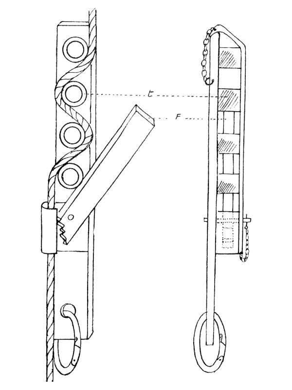
In about 1930, in the Grenoble region of France, French mountaineer and caver Henri "Kiki" Brenot created the Frein de Descente, a precursor to the Simple bobbin descender, which functioned more like a rack by weaving the rope between a variable number of bars. It was the first descender used for caving, and had a safety brake like a Stop. It is not known when it was first used for caving, but it was not used for the 1934 SRT trips. It was in common use by 1944. Carabiners were used with brake bars by mountaineers in North America since some time before 1933, which would be used in Europe around 1940-1942. These were always used with modern oval carabiners, and were quite dangerous, as the brake bar pushed sideways on the gate of the carabiner, and could potentially push it open if pushed slightly in the wrong direction. In 1933, German mountaineers rediscovered the carabiner wrap, despite it having been used in Germany for many decades already. Italian mountaineer/climber Emilio Comici developed the idea of using carabiners as a descender, running the rope through them and then over the shoulder and around the body like a body abseil, having been developed from the classic abseil, as a way to reduce discomfort, and improve safety. This damaged ropes fairly quickly, and required thicker hawser laid ropes. The date of the development is not known, but he was filmed using it in 1939. It later became known in English as an over the shoulder abseil (confusing it with one of the body abseil techniques), seat rappel, Swiss seat rappel, seat shoulder abseil or carabiner rappel (confusing it with all the other ways to abseil with a carabiner).
In 1942, the mountaineering booklet Anwendung des Seiles published by the Bavarian section of the German Alpine Club showed a carabiner with a brake bar, which was said to have been based on the approach used by mountaineer Ludwig Gramminger, and popular for a few years already. It is not known if he developed it before the American climbers, or whether he got the idea from them, but it is very unlikely that they were independent inventions. A single carabiner was not normally considered sufficient, so in use, it was attached to a tether from the chest harness so that it was positioned a little above the head, the rope was passed through it, down to a carabiner on the sit harness, back up to a carabiner hanging from the brake bar carabiner. The down rope and section of rope below the brake bar carabiner were held in the hands to control the speed, or the down rope could be wrapped around a leg to prevent motion, and free up the hands. This effectively created the same arrangement as the Petzl Simple (but on a larger scale), in addition to the brake bar carabiner. If the rope was wet, giving more friction, the extra two carabiners were not needed, and the sit harness could be connected to the break bar carabiner with a tether. If no brake bars were available, carabiners could be interlinked to effectively make a brake bar, but these could be even more dangerous than real brake bars, and were more prone to pushing or breaking them open. The suggestion was to tape them closed to avoid that (rather than using screw gate carabiners, which already existed!). A relatively modern example of a rod that the rope wrapped around, with ridges to guide it, is the descender made by French mountaineer Pierre Allain, which looks more like a torture device, with the prototype (which looked like a simple cross) dating from 1943, and the release versions dating from 1947, sold in 1949. American caver William Franklin "Vertical Bill" Cuddington adopted Emilio Comici's seat shoulder abseil in 1953 (his biography implied that he had developed it himself). This method was in use in British caving by 1963. In 1955, Dean Abbott invented the Rappel Log in Virginia, which Bob Geil made for the first time in 1956, shared with a caving club in 1957, and announced to other clubs in 1959. This was the first caving descender from the USA, which was simply a basic spool, and would have burned nylon ropes due to the heat that spools generated. It actually once set fire to a rope during use.
The figure of 8 was used as a descender by its inventor Austrian doctor and mountaineer Max Pfrimmer since the late 1950s. Carabiners were still being used as descenders where the old method of wrapping the rope several times around the spine got upgraded by American caver Bill Plummer in 1959, to using a chain of carabiners with the rope wrapped around all of them. Using interlinked carabiners as brake bars was common in North America by the 1960s, described by American caver Tom Perera in 1962. Two carabiners could be used as bars at the same time, to add more friction, with the rope passing over both of them as if they were a single, thicker bar. Some chained carabiners with brake bars together, to provide more friction. British climber Trevor Peck invented his terrifying descender around 1963, which was basically a carabiner wrap, with the carabiner gate completely missing. This twists the rope terribly, causes its user to spin as they abseil, and can very easily disconnect from the rope if the rope goes slack for a moment, or if the user breathes on it too hard. It was clearly inspired by Pierre Allain's descender, but seems to have been based on the principle that the Pierre Allain descender was not dangerous enough, and someone should make something even less reliable. French caver Bruno Dressler made a Simple bobbin in the Grenoble region of France in 1963, which was based on the earlier Frein de Descente, but using just 2 bars in the wrong order.
In 1963, British caver T. Charles Bryant suggested in the Wessex Cave Club journal that cavers should know "one of the carabiner methods" for abseiling, suggesting that he was referring to either a carabiner wrap, or the seat shoulder abseil. At the same time, he depicted the Trevor Peck descender as somehow being better for advanced cavers. He stated that other descenders would not work with the thicker ropes used for caving. The figure of 8 started to be more widely used in the early 1960s. Racks were made independently by American cavers John W. Cole and Warren Lewis, both in 1966. In 1968, Simples began to proliferate in Europe, and were advertised in the first British Descent magazine in 1969. In 1969, the first belay devices that could be used as descenders started to appear. In the same year, other descenders were being discussed in Descent magazine by British cavers. In the 1970s carabiners were again used for the Italian hitch. In 1972, Nick Reckert wrote about methods and equipment for potholing, in the Cambridge University Caving Club journal. The Pierre Allain descender was said to be dangerous because it could break or disconnect. Linked carabiners and brake bars were said not give enough control. The Simple (known as a "Roulette" at that point) was said to be good. The figure of 8 twists the rope a little, but was still said to be good. The idea behind the Stop was first experimented with in 1972, reinvented and presented in 1974, and the first commercial devices based on that principle appeared in 1977. The Stop itself appeared in 1979. The popular Petzl I'D rope access descender was patented by Petzl's sister company Zedel SAS in 1992, and operates on the same principle, but it was not sold until 2000. Most current Arborist devices, which can be used as both an ascender and descender, were produced from 2005 onwards, and these are covered in the section on ascenders. American arborist Kevin Bingham created the Rope Wrench in 2012, which is designed to add a little more friction, and make friction hitches more controllable when used as a descender.
This history section only covers descenders. This article also has a detailed history of many of the other devices and techniques that are used for vertical caving.
The most common descender, made by Petzl. Has an automatic locking system, where a handle is used to allow descent. Locking off can be relatively easily done with both a hard and soft lock, although the 2019 model makes soft locks impossible unless a braking carabiner is also being used.
The handle is not supposed to be used to control the speed of descent. The automatic locking feature is intended only to help avoid serious outcomes if mistakes are made, so that if the caver accidentally lets go of the down rope and the handle, it can hopefully save them. It will not be able to help if they press the handle further in when panicking. The automatic lock is supposed to be fully disengaged when abseiling, and the Stop is supposed to be locked off before letting go of the down rope. It can lead to a false sense of security and cavers sometimes intentionally let go of both the down rope and the stop handle, assuming that it will stop them like it normally does. However, this should not be relied on, since catching the handle by mistake can cause it to disengage, resulting in a very rapid descent. It also does not always engage fully if it is released during a fast descent, or if the rope is a thin diameter or very fast. This can be worse for lighter cavers as their weight may not be sufficient to cause the locking cam to pinch the rope hard enough. Creeping or slipping slowly down a rope is normal, and sometimes the handle needs to be manually forced out to increase the locking strength. This risk, and the fact that worn bobbins eventually cause the automatic locking system to become less reliable, led to them being affectionately known as a "Petzl Go" (a name that Petzl have given officially to one of their maillons).
The bobbins become very hot in use, and can easily singe a rope, especially on longer descents. Ropes may be intentionally wetted in order to reduce this risk. Difficult to use on very long hangs (over 100 metres), because the weight of the rope adds too much friction. Difficult to use with tight pitches, where there may not be space to reach a hand in front in order to use the handle. Models prior to 2019 allowed the handle to be clipped fully in with a carabiner (the small metal loop opposite the handle), making the Stop act like a Simple, allowing it to be used with tight pitches. Models after 2019 do not have this facility.
Many early descenders featured levers that could be used to control the descent speed, but most of them needed a force to be applied to make them slow down, rather than speed up. The first known descender to feature an automatic slowing mechanism which required a lever to be moved to allow motion was created by American Thomas C. Rice in 1871, for use as a fire escape. It functioned in a very similar way to the Stop, with the weight causing an eccentric cam to rotate, and apply force to the rope. A carabiner with an integrated pulley and braking lever was designed in 1882 by the German Lohner brothers, made for the fire brigades. It would automatically add friction when released, and reduce friction when a lever was pulled. This was described as being used either as a descender, or for lowering people, the way a modern Petzl GriGri is. The inventors complained about the pulleys falling off existing designs (which were not integrated within a carabiner), which seemed to also have a similar lever. No existing devices were described in a comprehensive manual from that region 5 years earlier. In 1884, American Marcus Henry Robb created a fire escape descender where the weight pulled on a lever, applying friction to a pulley. It could be adjusted to the point that it would automatically stop until the lever was moved, or the user applied pressure to the top of the descender. In 1888, Americans Lenious D. Smith and Wilson Albert Olds created a fire escape descender where the weight pulled two levers onto the rope, creating enough friction to slow or stop the descent. Handles could be pulled to control the speed.
The first descender used for caving, the Frein de Descente, had a safety brake that would immediately automatically lock the rope, if a handle was not held open. It was created by Henri "Kiki" Brenot in about 1930, and was described in Henry P. Guérin's 1944 book "Spéléologie, manuel technique; Le matériel et son emploi Les explorations". This descender was the ancestor of the Simple and the Stop. Cavers then learned that by using the bars in the wrong order, and therefore wrapping the rope further around each bar, they could reduce the requirement down to 2 thicker bars, which became the bobbins of the Simple. French caver Bruno Dressler made the first Simple in the Grenoble region of France in the 1960s, before giving the design to the founder of Petzl, who released their Simple in 1968 (before Petzl existed as a company). Several companies then created descenders that used a rotating cam to automatically lock the rope. In 1972, British caver Guy Talbot and Cambridge University Caving Club researchers developed and tested a fall arrester which used the exact same fixed bobbin and rotating cam arrangement as the Stop. The intention was that the lever could be used to disengage it after a fall, and turn it into a descender. However, because it did not function well as a fall arrester, they abandoned the idea, without realising that they had just invented what would have been the most popular European descender. B. D. Butkovič (country unknown, but the name is typically Slovenian or Slovakian) apparently presented the approach of interlocking bobbins at an Italian caving conference in 1974. Italians Costantino Bottoli and Mauro Venier created the BO.VE Diabolo in 1977, which looked almost exactly like the Stop, but was quite poor at automatic locking, and wore out very quickly. Kong released the Giuseppe & F.lli Bonaiti branded descender in 1977, which used a separate cam to automatically lock the rope. Bruno Dressler's automatic locking descender, called the DAD, had a moving front cover as a handle, and was patented 1979, one month before Petzl patented the Stop. The first version of the Petzl Stop was originally developed in 1979, and was barely changed until 2019. It had the auto-lock based on a rotating cam that pinched the rope in exactly the same way as the BO.VE Diabolo, but it worked far more reliably due to small differences in the cam shape. In 2019, a new model was released that used steel bobbins instead of aluminium, and a flip-out handle. The bobbins could no longer be replaced, and there was no facility to lock the Stop into acting like a Simple.
This history section only covers the Stop. This article also has a detailed history of many of the other devices and techniques that are used for vertical caving.
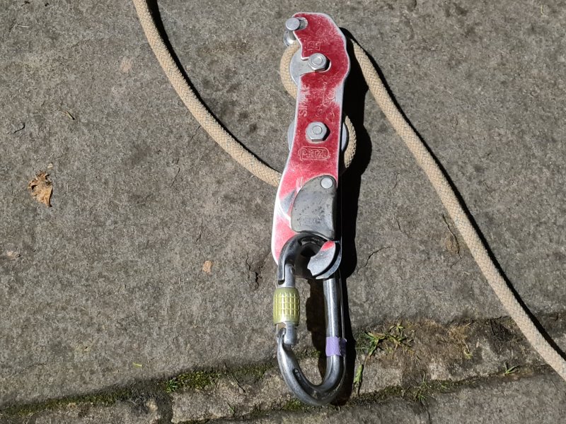
A simpler version of the Stop, which has no automatic locking system. This works using the characteristic S-shape of rope wrapped around two metal bobbins, common to almost all bobbin descenders, where the up rope comes out of the bottom of the descender, and the down rope comes out of the top of the descender. Locking off can be relatively easily done with a hard lock, but there is no soft lock unless a braking carabiner is also being used. The bobbins become very hot in use, and can easily singe a rope, especially on longer descents. Ropes may be intentionally wetted in order to reduce this risk. Difficult to use on very long ropes, because the weight of the rope adds too much friction.
In 1865, German fire brigades used an Archimedian scroll descender which operated on exactly the same principle as the Simple, with the two bobbins attached directly to a waist belt side by side instead of above each other. The friction was said to be fairly low, and the rope needed to be prepared using rosin to make it grip more once the bobbins wore down, but this is probably because of the orientation of the bobbins, and because they did not expect speed to be controlled with a hand. This approach for a descender was then described as a fire escape system by American E. K. Graves in 1878, but with two extra bends that the rope had to twist around. After a couple of others used the same approach, American Oscar F. Davis changed the orientation to match the Simple in 1882, and added a lever to adjust the friction. In about 1930, Henri "Kiki" Brenot created the Frein de Descente descender in the Grenoble region of France. It was based on the same weaving principle as a rack, with 4 fixed bars and a removable front. The number of bars could be varied if fewer were needed. Cavers then learned that by using the bars in the wrong order, and therefore wrapping the rope further around each bar, they could reduce the requirement down to 2 thicker bars, which became the bobbins of the Simple. French caver Bruno Dressler made the first Simple in the Grenoble region of France in the 1960s, before giving the design to the founder of Petzl, who released their Simple in 1968 (before Petzl existed as a company). The modern versions look almost exactly the same (with some paint) and function in the same way. The Simple was advertised in the first British Descent magazine in 1969, and was originally known as the "Roulette" in France and Britain.
This history section only covers the Simple. This article also has a detailed history of many of the other devices and techniques that are used for vertical caving.
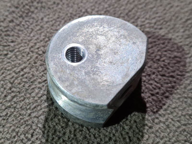
A larger descender favoured in the USA. Uses a number of metal bars to create friction, which can be moved or disabled in order to alter the friction, making it usable on a very wide range of rope lengths. The rope weaves alternately in front of and behind one bar at a time. Descent is smoother than most other popular descenders, but it is harder to use in some situations, and takes longer to attach. Speed can be controlled much more than with other descenders. If disabling some bars at the top of a hang, it is very important to re-enable them as needed when the weight of the down rope decreases during the descent, to avoid an uncontrolled descent. Dissipates heat much better than most other descenders, and is less likely to singe the rope. Can work with single or doubled ropes, and ropes of almost any standard diameter. Locking off is quite clumsy, with soft locks being possible only on some designs, and hard locks need a lot of excess. Several designs, with the most common being an open frame J rack, and the second being a closed U rack. Most designs allow the user to freely reconfigure their rack bars, to swap bars around to even the wear across all bars, to change whether the first bar is threaded from the front or back, or whether the bars hinge on the left or right. However, this should only ever be done by a skilled user, as changes may be confusing, may remove safety features, or can make the rack dangerous. And of course, any modification (such as the one pictured) is likely to be contrary to the manufacturer's PPE instructions and/or invalidate warranties, so anyone choosing to make modifications must ensure that they are fully aware of the implications.
A Belgian inventor created a device that functioned exactly like a rack, which was presented at an international rescue conference in 1876. The number of bars could not be changed during use, and it could only be threaded on to the start of the rope. By 1877, descenders based on the Belgian design were being sold by German fire brigade suppliers from southern parts of the German Empire (now Germany), such as Magirus in Ulm. American James Jerome van Wie created an almost identical design in 1877. Americans William N. Clark, James B. Clark and William N. Clark Jr. created another design in 1877 that functioned like a rack, but with a lever that could squeeze the rope to adjust the friction during use. These American designs were registered on the same day in different places, and seem to be independent inventions, but appeared some time after the Belgian and German designs, and were likely to have been derived from the Belgian design. Further designs used the same approach in 1884 in Canada, 1886 in Germany, 1887 in Germany and 1890 in the USA. In about 1930, in the Grenoble region of France, Henri "Kiki" Brenot created the Frein de Descente caving descender, which functioned like a rack by weaving the rope between a variable number of friction bars, but with fixed bars attached to one plate like a Simple, and a removable front. The French model allowed the number of bars to be varied if the rope needed less friction, and used an eccentric cam as an emergency brake. Carabiners were used with brake bars by mountaineers in North America since some time before 1933. They were used by the American military in the years they were involved in World War II; 1941-1945. In 1942, the mountaineering booklet Anwendung des Seiles published by the Bavarian section of the German Alpine Club showed a carabiner with a brake bar, which was said to have been based on the approach used by mountaineer Ludwig Gramminger, and popular for a few years already. It is not known if he developed it before the American climbers, or whether he got the idea from them, but it is very unlikely that they were independent inventions. Using interlinked carabiners as brake bars was common in North America by the 1960s, described by American caver Tom Perera in 1962, but like actual brake bars, these could be very dangerous, as the brake bars pushed sideways on the gates of the carabiners, and could break them open. The first proper devices that look like a modern rack were made independently by Americans John W. Cole and Warren Lewis, both in 1966. In 1967, American Gerald Wood created the Whaletail, a version of the rack milled from a single block of aluminium, with one side open, holding the rope in place with small protrusions. The bars were not adjustable, but the heat dissipation was better than a standard rack. These were popular for a while, but lost out to the regular rack after some serious safety incidents. John Grindstaff created the hyper bar, then called a "John-Bar" around 1970. Petzl released their rack in 1987, which is one of the very few European racks still in existence.
This history section only covers racks. This article also has a detailed history of many of the other devices and techniques that are used for vertical caving.
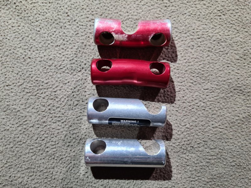

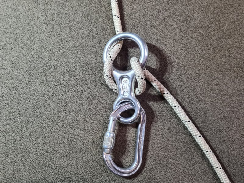
A very simple descender with no safety features. Within Britain (and in fact most of Europe), this is only used for education, never in caves. However, it is used within caves in parts of the USA, particularly regions where indestructible rope technique is used. Can also be used as a belay device. Twists the rope badly. Normally has to be completely disconnected from the D-ring in order to connect it to the rope, so there is a very real risk of accidentally dropping it down a pitch, particularly when hands are cold or tired. Keeper cords cannot be used to avoid this, because they prevent the rope from being wrapped around the descender. It is possible, but clumsy, to connect it to the rope without removing it from the D-ring, by swapping the positions of the rope and figure of 8 descender within the carabiner that connects the descender to the D-ring, while clipping the rope in and out of the carabiner. If this goes wrong, then the descender can be dropped by mistake, or can become jammed on the carabiner's gate. So this does not really solve the issue of accidentally dropping it.
There are several different ways the rope can be threaded through the figure of 8 descender, producing different levels of friction, or to make it automatically lock and prevent descent until it is pulled in a specific way. Some figure of 8 descenders may have extra little arms or holes, to provide further friction levels. However, the most common method is to take a bight of the rope through the larger hole, pull the bight over the small hole so it rests on the bar between the holes, then clip the smaller hole into a carabiner. Some users are adamant that the bight should be fed into the front of the larger hole, while others are determined that it should be fed through the back of the larger hole, but the reality is that since the descender sits vertically during use, it makes very little difference with a standard figure of 8 descender, and it is a matter of taste. Some of the other arrangements, particularly ones where the carabiner is clipped to the bigger hole, are downright dangerous when performing manoevers which could cause the load to be briefly removed from the rope, such as Y-hangs and rebelays, as the rope could simply fall off the figure of 8. Be warned that many tutorials on this subject conveniently assume that the rope will always be loaded, and that Alpine rigging does not exist.
By 1904, a fire brigade descender that operated on the same principle as a figure of 8 descender had been developed in Leipzig and Stuttgart, German Empire (now Germany), with an additional hole to get a little more friction. The actual figure of 8 descender was first invented in 1943, by Austrian doctor Max Pfrimmer. It was intended to be used for lowering objects on a rope, and it was not until the late 1950s that it was used as a descender by its inventor. It was first sold commercially as a descender in the early 1960s in München, Germany, then by 1963 in Britain, and 1965 in the USA. It was the first descender in common use in British caving, and was used during the 1971 and 1972 British expeditions to Ghar Parau. It only became popular in the USA after 1974.
This history section only covers the figure of 8 descender. This article also has a detailed history of many of the other devices and techniques that are used for vertical caving.
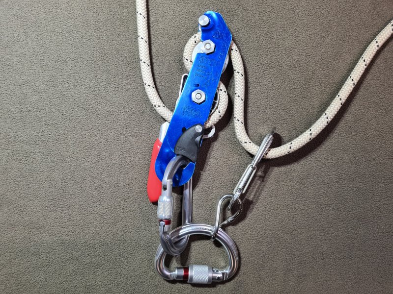

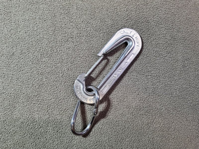
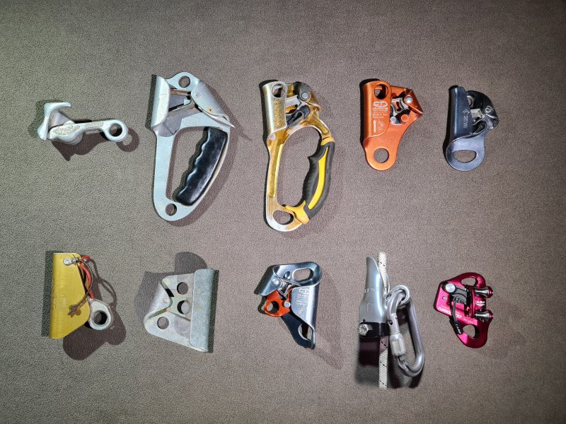
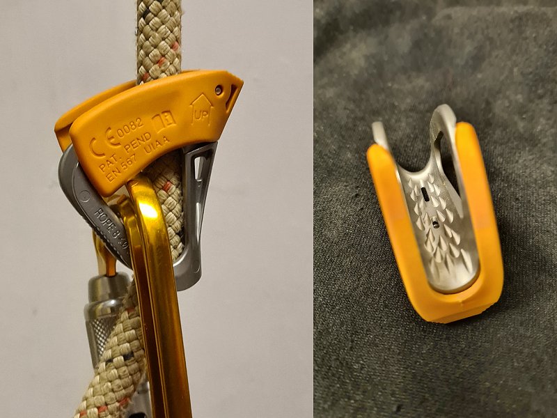
The devices used to prusik, which can grip and release the rope as needed. Commonly used in pairs (typically a top jammer and chest jammer for the frog system) to alternate which one is gripping the rope, and which one is moving. Additional ascenders can be used to allow rope walking, or provide other benefits. Ascenders are generally considered to be the weakest part of any normal PPE rated SRT gear, and therefore at least two must have a secure connection to the sit harness at all times, in case one fails. (Many designs, many brands, many names.)
The vast majority of ascenders rely on a mechanical ratchet called an eccentric cam to clamp the rope when it moves through them in one direction, and release it in the other. The majority of ascenders use small metal teeth to ensure that the movement of the rope causes them to clamp the rope reliably, with a spring that pushes the teeth against the rope. This causes no damage to the rope during normal use, but can make them dangerous to use in a shock loading situation (such as when self belaying), as they can tear through the rope's sheath. Many cavers, in Britain or North America, used to call these Jumars, after the Jumar ascender, which was the first one to use that approach with a single eccentric cam.
Older designs, and a minority of modern designs rely on the caver's weight to pull down on a lever, pinching the rope, known as a lever cam. In North America, these might just be called a "cam", which is confusing, since almost all ascenders use a cam of some kind. Lever cam ascenders normally cause less damage to the rope when shock loaded, but often fail to grip on muddy ropes. They can bend the rope quite hard when loaded, and long term use can cause ropes to wear out a little faster. This type of ascender must not be held in the hand while they are gripping the rope, as a downwards force on the body of the ascender can cause them to disengage. Some lever cam ascenders need a sharp downwards pull to make them grip the rope in the first place, which can make them a little harder to use. However, this feature means that they can often be moved down the rope very easily when not loaded, which is more convenient than eccentric cam ascenders for some purposes, such as reverse prusiking. These devices may be designed specifically for catching a fall, and are sold as fall arresters, rope grabs or rope clamps when aimed at rope access usage, even though they are essentially just ascenders.
Some designs, such as the Petzl Tibloc, rely on teeth to pull the device into a position where it compresses the rope against something, such as a carabiner. These risk damaging the rope more easily, as the teeth are an integral part of how they work, rather than using clamping force, with the teeth just to make sure the cam moves properly. They are generally not suitable for frequent use, because of the risk of damage to the rope. Many types of progress capture pulley can also be used as an ascender. These typically use a very small eccentric cam, but they often rely on the teeth to grip the rope much more than a standard eccentric cam ascender, and they often bend the rope significantly during use, so they are not as gentle to the rope as dedicated ascenders. However, they are sometimes used as an emergency ascender. Both the Tibloc and progress capture pulleys are very inconvenient for some manoeuvres, such as reverse prusiking. Most need to be completely removed from their carabiner to remove them from the rope, which risks dropping them when performing manoeuvres, so they need a keeper cord to catch them, but this must be done in such a way that it does not interfere with their normal operation.
There are also some devices that can double up as an ascender and descender, which may be known as a multicender in arboriculture. The most basic ones are simply an ascender and descender bolted or welded together, but dedicated devices are usually a single device that can perform both functions depending on how they are configured. These never really caught on due to their complexity, and excess of moving parts, often with adjustments needed for each different rope type or diameter. They do not normally cope with the mud and changing conditions they would encounter in caves. Some do not even cope with a change between dry and wet ropes, and may need adjustments to be made every time. Their use is mostly confined to the arboriculture world where mid-rope changeovers are very frequently required. Examples include the Rock Exotica Unicender, the Notch Rope Runner series and the Rock Exotica Akimbo, which are simply unusable for caving because they cannot cope with the variety of ropes used there, and all wear out far too quickly when used with muddy ropes (even with clean ropes, they wear out far more quickly than caving devices). Some of them can only be threaded onto the end of a rope, such as the Petzl Zigzag.
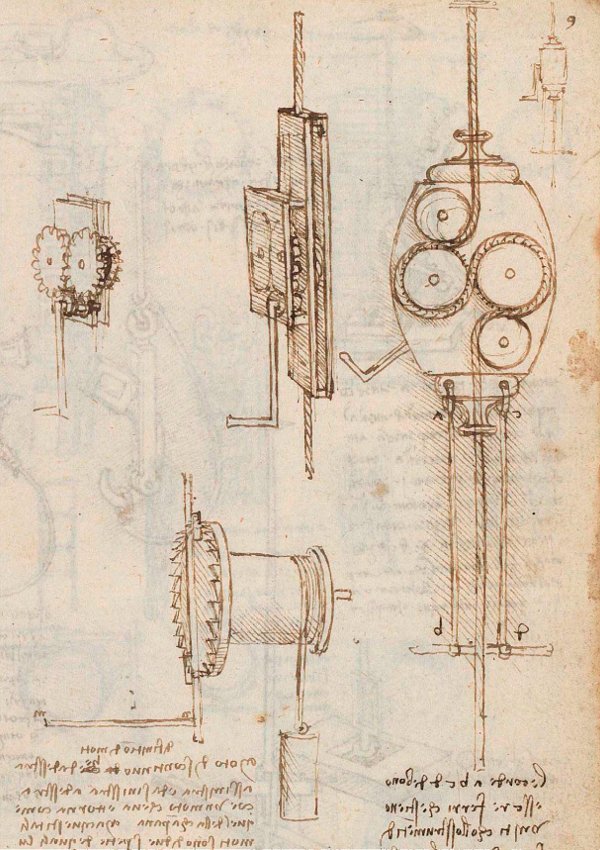
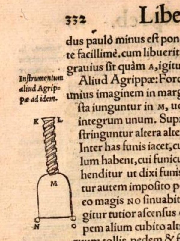
Between 1495 and 1497 in the Holy Roman Empire, now Italy, Leonardo da Vinci designed a mechanical ascender that used a rotating handle, which turned pulleys that gripped the rope as it passed around between them. A ratchet prevented it from rotating in reverse. It was not used with any standard prusiking system, and like most of his inventions, it was probably never built. In 1550, polymath Gerolamo Cardano published a book called De Subtilitate Rerum (On The Subtlety/Intricacy/Finesse Of Things) in the Holy Roman Empire (now Italy), which included details of ascenders which he attributed to Heinrich Cornelius Agrippa von Nettesheim (whose first name might be written as Henry or Henricus), from the Holy Roman Empire (now Germany). (An English translation of a later edition is available, but it gets some of the important details wrong.) The design is very similar to a pair of tongs or pliers, and they were referred to as "forcipes" (a pair of forceps) in Latin. The grips were shaped the same as the twists of a hawser laid rope and interlocked into that shape when closed, so that they could hold very firmly onto the rope, and they would not have worked as well on a smooth, modern rope. The handles had a piece of rope joining them, and stepping on that piece of rope would pull the handles together, forcing the grips closed, and heavier users would cause them to grip even harder. Their design was probably inspired by the stone tongs used on cranes to lift heavy rocks, as they function in exactly the same way. They were intended to be used with the two ascender variation of rope walking, with one ascender strapped to each foot. They were not designed to be slid up the rope, however, and had to be taken off the rope, moved upwards manually, then reconnected to the rope higher up, which would have been incredibly fiddly, and risked dropping them. The date of their creation is not specified, but it was probably 1520-1530, when Heinrich Cornelius Agrippa von Nettesheim was adding details of how to cast metals to his book series De Occulta Philosophia, and definitely before his death in 1535. He served in the Spanish and Holy Roman Empire militaries from 1508 to 1515, was an academic lecturer from 1509 to 1519 and continued with academic research afterwards in many parts of the Holy Roman Empire. He was established as a polymath, well known for having a great interest in science, mechanics, natural magic, alchemy and philosophy. He probably developed them simply out of curiosity, believing them to be useful for rope access. Knowledge of them, however, seemed to remain entirely within academic circles, and they were not described as being used anywhere. Gerolamo Cardano stated that he had actually seen the physical devices, so they were not just theoretical.
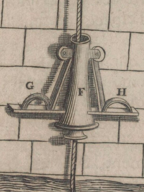
Most of the early standard ascenders were clamping jaws, which were essentially a pair of opposing lever cams, pushing at the same time from opposite sides of the rope. This meant that they needed to be pushed downwards on both levers together, with the same amount of force. The majority of these were therefore expected to be strapped to the feet or held in the hands, with both feet being used together, and both hands being used together. The earliest known clamping jaws ascender that was designed to slide up the rope was created by French inventor Nicolas Grollier de Servière, which he called pincers or pliers ("tenaille" in French). The exact date of its invention is not recorded, but it was during his retirement which began in 1642 and ended with his death in 1689. It is likely to have been shortly after obtaining the 1647 French translation of a book by Galileo Galilei, which inspired the inventor's research into rope access. The details of this ascender were then included in a book by his grandson Gaspard II Grollier de Servière in 1719, along with instructions for its use, which show that it was intended for use with the hands and feet system. There was only a single ascender, designed to be used as a foot jammer for use with both feet at once. Its purpose was to ascend a castle wall during an invasion, or ascend into the window of a tall building.
In 1700, the book "Recueil de plusieurs machines de nouvelle invention" was published, containing the mechanical research of Claude Perrault, a French physician and architect. One of these was a clamping jaws ascender called "Main" (French for "Hand") or "Analemme" ("Analemma"). This was intended to be used as part of a crane, to provide progress capture for a pulley. He had died in 1688, and he was probably working on the book at the time of his death. Unlike other clamping jaws designs, the two jaws were linked, so that they moved at the same time. A spring forced them to make contact with the rope, and the weight on the ascender would then result in them clamping the rope. This meant that they would not need both hands to be used at once, or both feet to be used at once, and could have been used for any prusiking system, if only this ability had been realised. In fact, this approach is extremely close to how a modern sprung eccentric cam device works, but using two opposing eccentric cams instead of the modern single cam. In 1725, German engineer Jacob Leupold from the Holy Roman Empire (now Germany) added pairs of handles and stirrups to Claude Perrault's ascenders, and used them with the hands and feet system, adding a tether between the ascenders to avoid accidentally dropping the foot jammer. Reverse prusiking required pulling a string or pushing a lever to open the clamping jaws. The spring made bottom weighting difficult, and the suggestion was to hang a rock on the bottom of the rope, but the lever would also have worked. Jacob Leupold also recommended a modification to Nicolas Grollier de Servière's ascender, to make it grip the rope with more force. Both ascenders were suggested as a way to escape a fire using a rope, by reverse prusiking.
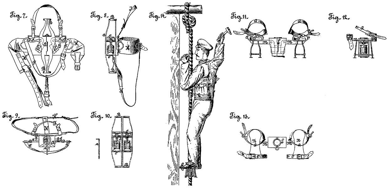
Another set of clamping jaws ascenders were patented in 1878 by German inventor Ed. von Mengden, presumably inspired by the "tree climbing spikes" or "spurs" worn by arborists, and trying to come up with something less damaging. They were not designed to be used for ropes, and had a highly complex width adjustment for wide poles such as telegraph poles and observation poles, or for pioneers climbing the ramparts of fortresses (this is not a joke!). These were intended to be used with the hands and feet system. In 1879, the same inventor updated the design, and added a second design for ropes, with one in a large housing strapped to the chest as a chest jammer using a full body harness, and one strapped to the feet, which would be used with the inchworm system. In 1885, American George M. Heath created a simplified ascender for cables based on the clamping jaws approach, intended for use with the hands and feet system, but without any safety measures. In 1893, Swedish inventor Anders Wilhelm Lewin created a rope grabbing device based on the clamping jaws principle that also featured a descent lever, so it could be used as both an ascender and descender. American William E. Burke patented an ascender in 1897 that used the clamping jaws approach, where the clamping force pushed the rope sideways between two rings, holding it in place with shear stress. It was intended to be used with the hands and feet system, but without any safety measures, and without any ascender held in the hands; the hands had to hold the rope directly. Apparently, this was a "useful improvement".
New Zealand inventor Robert Cockerell (who specifically wrote as a British subject!), patented the first lever cam ascender in 1902, which looked almost identical to the Singes Mécaniques (which would appear later), and could function on either ropes or poles. It worked as an ascender when pulled in one direction, and a friction descender when pulled in the other direction (where it did not provide enough grip to be an ascender). It was intended to be used with the two ascender variation of rope walking, with one ascender strapped to each foot. It was almost certainly created in 1901 or earlier. In 1902, American inventor Charles E. Knop patented an ascender based on the clamping jaws approach. It was intended to be used with the hands and feet system, without any ascender for the hands, and without any safety measures. This was once again claimed to be a "useful improvement". In 1903, British inventors P. and W. MacLellan and James Dougall patented the same basic idea, except they also strapped a large plank to the feet, covered in paint pots, that the user was expected to lift upwards with their feet, while holding on to the rope with just their hands! It also featured a lever that could be used to turn it into a descender. In 1904, a lever cam device was patented by Austrian locksmith Michael Gayer, which he called a "clamping sleeve for climbing devices". This was sold as a "climbing device" by F. Turczynski Jagd- und Touristen-Asrüstingen, a mountaineering shop in Vienna, Austria, the city where Austrian mountaineer Karl Prusik lived, run by a member of the Wiener Alpenklub (Vienna Alpine Club), which Karl Prusik was also a member of. The design had a very limited range of rope sizes which it could work with, and used a fiddly bolt and wing nut to close a hinged section around the rope, which would have been very easy to drop by mistake. It was advertised only as a fall arrester in Austrian mountaineer E. Fink's Touristen-Vademekum publication in 1904, for self belaying when climbing up or down, for climbers, quarry workers, miners, construction workers, roofers and plumbers. In 1910, American inventor Iver J. Westad re-invented clamping jaws, but very much simplified this time, intended to be used with the hands and feet system with two ascenders on a rope. German mountaineer H. Sixt proposed a lever cam device, which German mountaineer Franz Kröner then improved and manufactured in 1911, called a "climbing lock". It was intended to be used as a self belaying device while abseiling, but could have been better used as an ascender. Karl Prusik claimed in 1931 that the "climbing locks" could not be used when the ropes swelled because they got wet, and while he did not clarify which devices he was referring to, it was probably the devices made by Michael Gayer and H. Sixt.
In 1913, Austrian inventor Johann Machek patented lever cam devices, with one strapped to the feet, and one attached in front of the body, with a boatswain's chair hanging off it. It was intended to be used with a variation of the inchworm system, requiring foot tilts to disengage the foot jammer. It was intended to be used by exterior decorators, and is incredibly similar to the later design by Antoine Joseph Marius "Paul Cans" Barthelemy, which received much more attention. In 1913, American "inventor" Linn Fenimore Cooper invented perhaps the most simple ascender, which worked by bending the rope sharply as it passed through a narrow gap, and could be described as little more than a board with a hole in it, but apparently it was enough to earn a patent! You could patent a board with a nail in it, if you manage to get there early enough. Not only would this rapidly damage the rope, but it also would have been impractical to use more than one at a time. It was intended to be used with the hands and feet system, without any ascender for the hands, and required careful manipulation using the feet to move it up the rope while gripping directly onto the rope with the hands. Amazingly, it does not appear to have been a joke, and someone must have thought it was worth paying for the patent. Also in 1913, American engineer Egbert Whitney patented clamps for cables that would use gravity to force a wedge to close on a cable. When used in pairs, these could be used as ascenders for scaffolding platforms. In 1919, German Heinrich Schnurer re-invented simple clamping jaws with a chest harness for safety, intended to be used with the hands and feet system.
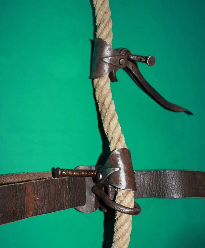
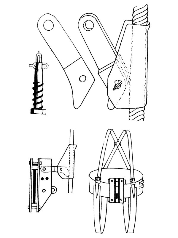
The first mechanical ascender intended for caving was a prototype lever cam device created by French caver Léon Pérot in 1920. In the same year, Antoine Joseph Marius "Paul Cans" Barthelemy invented the lever cam Ouistiti (marmoset), intended as a way to paint buildings, which was revealed at the start of 1921 by ascending to the first platform of the Eiffel tower. He also used them to hang things on the rope, particularly for bottom weighting. While most lever cam devices simply trap the rope, his worked by bending the rope sharply between two rings where it was held straight, which would probably cause a lot of shear stress on the rope. The first devices actually used by cavers were French caver Henri "Kiki" Brenot's Singes Mécaniques (mechanical monkeys), which were made in 1929, originally intended for mountaineering, and first used underground in the Félix-Trombe cave system in the French Pyrenees along with Pierre Chevalier in 1934. These can be seen in Henry P. Guérin's 1944 book "Spéléologie, manuel technique; Le matériel et son emploi Les explorations", and were virtually identical to the Gibbs ascender. They were inspired by something that French well diggers had been using, which was presumably something based on Robert Cockerell's ascenders. Alpinist Magazine says "the device consisted of two pieces: a curved metal plate that held the rope and a removable L-shaped camming arm fixed to the plate by a pin", where a strap or belt could be "attached to the camming arm through a hole at its top". The main criticisms were that they were fiddly to use and damaged hemp ropes fairly quickly. Henri "Kiki" Brenot also developed the Frein de Descente descender in about 1930, which had a safety brake. The safety brake was almost identical to a modern eccentric cam ascender, using gravity instead of a spring to make it engage with the rope, and could have been used as an ascender, if only this ability had been realised. It would have been far more easy to use than the Singes Mécaniques.
The first modern type of sprung eccentric cam device was the Jümar, which became commercially available in 1958, at least 270 years since the Main (Hand) first used a sprung eccentric cam! This is often stated as being the first mechanical ascender, or the first commercially available ascender, but neither of these is true, as there had been several commercial ascenders available for as much as 80 years at that point, and mechanical ascenders had been in use for around 400 years. However, Jümars were the first commercial mechanical ascenders known to be used for caving ("climbing locks" had already been used for climbing). Adolph Jüsi was studying eagles for the Swiss government, and had asked Walter Marti to develop the ascender for him so that he could reach them. Together they ran the company Jümar Pangit in Reichenbach, Switzerland, which sold the Jümar. The name Jumar is sometimes used for all ascenders as a result. The name was spelled Jumar as early as 1960 in English speaking markets, and they were sold that way when sales became official in those countries. The name was also pronounced as an English word in those markets, instead of a German word. French caver Bruno Dressler then modified these in the Grenoble region of France to remove the handle in 1959, and made a relatively small ascender in 1963, originally known as a Schtroumpf (Smurf). It was then produced for others to test in 1964. These variations are the basis of almost all modern ascenders. German company Salewa released the ridiculously minimal Heibler lever cam ascender in 1963. Americans Wegstein and Danhof (presumably cavers) described a twin lever cam ascender from America in 1963, which is basically a clamping jaws ascender.
In 1963-1964, the Light Engineering group within the British South Wales Caving Club developed ascenders for cables, based on a commercial emergency cable clamp. These operated based on the idea of a long, narrow parallelogram, where changing the angle of the ends pulled the two long sides closer together, trapping the cable between them. The leverage was created by a lever attached to the ends, with a spring that pulled it closed, while the weight of the person then pulled the lever harder. The cable ran in a groove in each of the two sides to keep it between them, with a roughened surface so that it would grip the cable, and be more inclined to grab it. This is somewhat similar to a lever cam device, but with the leverage applying over a much longer length. The spring cause it to scrape quite roughly up the cables when being slid upwards, and poor quality metals would quickly be worn away. One of the ascenders had handles sticking out the sides for holding on to, and the other had foot plates for standing on, so it functioned as a mar-bar. With the handled one, the lever could be pulled downwards to release the grip on the cable, and on the other one, one of the foot plates could be tilted forwards to pull the lever downwards for the same reason, so that reverse prusiking was possible. Americans Robert E. Henshaw and David F. Morehouse (presumably cavers) made a lever cam device called the Climbing Cam in 1965 that was very similar to the Singes Mécaniques but was an independent design, followed by Dwight Deal's Infernal Machine, and Pete Lindsley, who all copied each other (all presumably cavers).
American caver Charles Gibbs created the Gibbs ascender some time around 1966. American caver Jack Speece described the Bat Climber in 1968, another clamping jaws ascender. American company Gibbs released their ascender in 1969, and despite being an almost direct copy of the Singes Mécaniques that people previously complained about, they were a big success. This was mainly because the three Gibbs version of rope walking was created especially for them, and had been proven to be much faster than the Jumar system which had been recommended for Jumars. Designs proliferated. In 1969, Clogwyn Climbing Gear released the first British commercial ascender aimed at mountaineering or caving, the basic Clog, affectionately known as a Clogger or Cloggar, which was based on Bruno Dressler's ascender. The French approach of using an ascender for self belaying while using ladders was described in Britain in the Westminster Speleological Group Bulletin Jan/Feb 1969, referred to as a brake-blocker, which is an early term for an ascender (bloqueur in French), but in 1970, Clogwyn Climbing Gear told Descent magazine that theirs was not suitable for that task, because it could be affected by mud, and fail to work. By 1970, Petzl had released the first version of the Basic ascender, which was based on Bruno Dressler's ascender, and it was already being advertised in the British Descent magazine edition 10 in that year. Carabiners were being used as emergency ascenders, using the Alpine clutch, which was created by Italian Franco Garda in 1970. After the British caving expedition to Ghar Parau in 1971, where the Jumar had been the most popular ascender, Clogwyn Climbing Gear released the handled Expedition ascender, possibly in the same year. During the 1970s, many people again experimented with combining the functionality of an ascender and descender into one device (rather than two devices bolted or welded together), such as the Bugat developed by father and son Bugat and Francis in 1974-1975, the Whillock Rope Climber made by British caver Martin Whillock in 1975, the French S.A.R.L. Voynett Tracson created by Denis Motte in 1978, and the British Dick Lawson Multiscender from the late 1970s. These never really caught on due to their complexity, and excess of moving parts, which rarely cope with the mud in caves. Petzl released the Shunt in 1972.
The rocker aproach to ascenders, now far more common with fall arresters, was developed in 1975 by Russian mountaineer Виктор Алексеевич Козлов (Victor Alekseevich Kozlov), as an approach that worked more reliably on frozen ropes. The up rope pulls on one end of a rocking lever, trapping it at the other end of the lever. It was then refined in 1980 with the help of Борис Бергандович Паникаров (Boris Bergandovich Panikarov) and Сережа Мамаев (Seryozha Mamaev), and made for friends as the Капелька ("Kapelka", meaning droplet). A handled version was made in 1983, which could also be used as an extremely clumsy descender by threading the rope through the handle. They were commercially sold under the brand Ural-Alp in Russia in 1993 and USHBA internationally from 1995, at which point the idea became widely known, and the approach started being used for fall arresters. In 1985, British caver Jim Roberts created a cycling device for prusiking on free-hangs, literally a bicycle arrangement with rotating handlebars and pedals on an upright frame. For some reason, this never caught on, even after being demonstrated in 1991 and 1992. American arborist Daniel F. Brennan created the Arborist Cinch in 1987, a combination ascender and descender.
Progress capture pulleys (pulleys with an integrated ascender cam) started being made by the late 1980s, and part way through the 1990s, they started being made with a design that allowed them to be used as an ascender. The Ural-Alp Hauler, released in 1994 or 1996 (depending on which website you read) was the first with the right design, but could only be used by people weighing less than 25 kg, such as small children. British company Wild Country released the first miniature ascender, the Ropeman, in 1996. Petzl released the Tibloc in 1998. By 1999, the first prototypes of the Petzl Mini Traxion had appeared, which were the first known progress capture pulley to be strong enough to be trusted as an ascender, as well as being designed in a way which allowed that. Combination ascender and descender devices became popular in the arboriculture world, where the Rock Exotica Unicender was created by American arborist Morgan Thompson in 2005, which uses a series of hinged metal plates to weave the rope through increasingly sharp bends, and clamp it between the plates in much the same way as a pair of scissors. This is the same basic approach that Antoine Joseph Marius "Paul Cans" Barthelemy had used. The Hitch Hiker was created by British arborist Paul Cox (while based in the USA) in 2012, an arborist device that relies in part on having a friction hitch above it. American arborist Gordon Svedberg made the Bulldog Offset Ascending Rack in 2012, which is an obvious copy of the Unicender. The Singing Tree Rope Runner was announced by American arborist Kevin Bingham in 2013 then sold in 2014, the Bulldog Bone was created by American arborist Gordon Svedberg in 2014 and the Rock Exotica Akimbo was created by American arborist Jaime Merritt in 2014, all of which are very similar to the Bugat, designed for arborists. Petzl patented the Zigzag in 2010 and marketed it at the end of 2012, but it was not actually released until 2013.
This history section only covers ascenders. This article also has a detailed history of many of the other devices and techniques that are used for vertical caving.
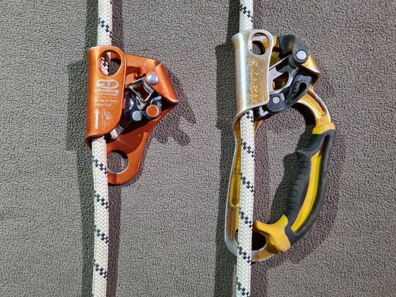
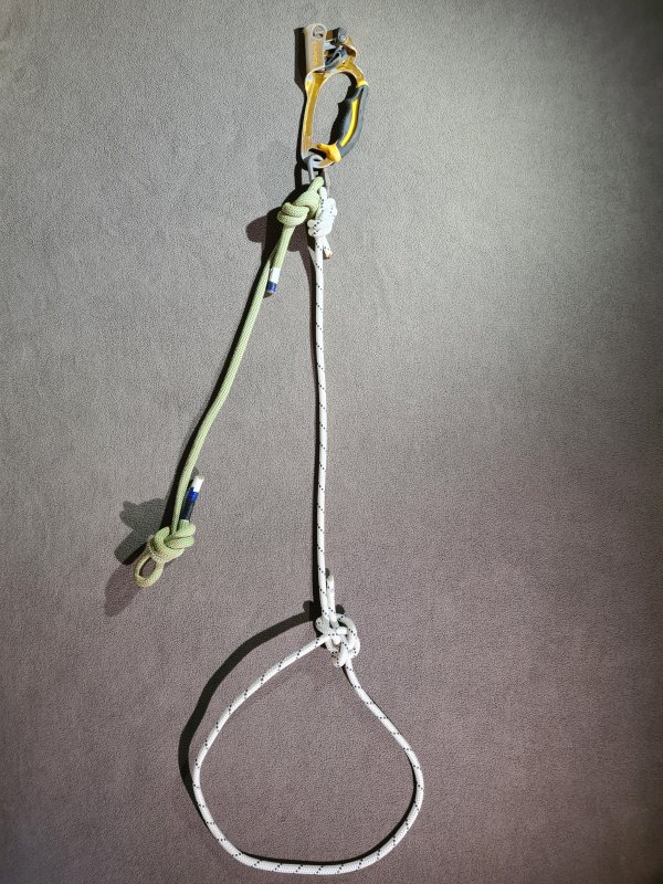
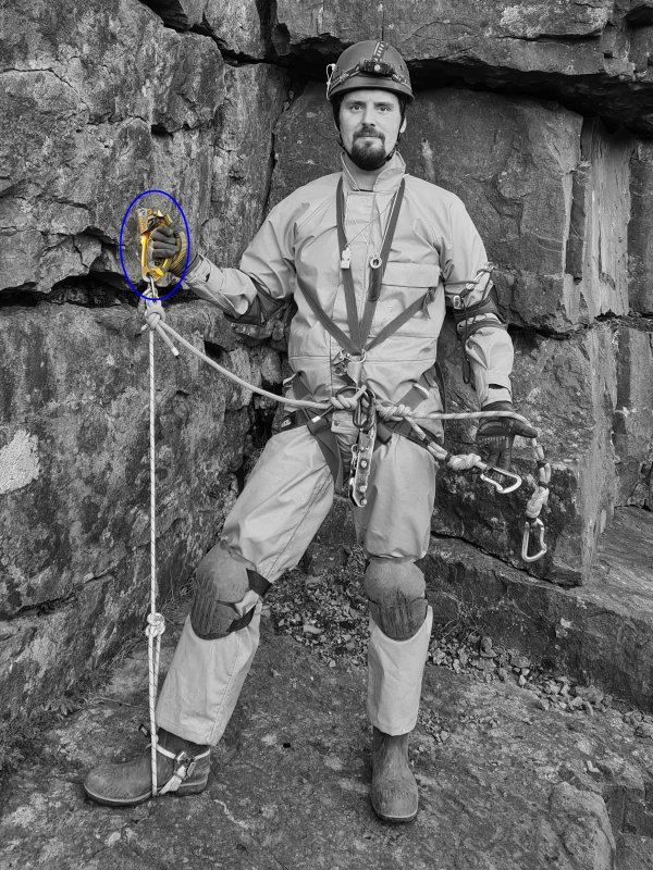
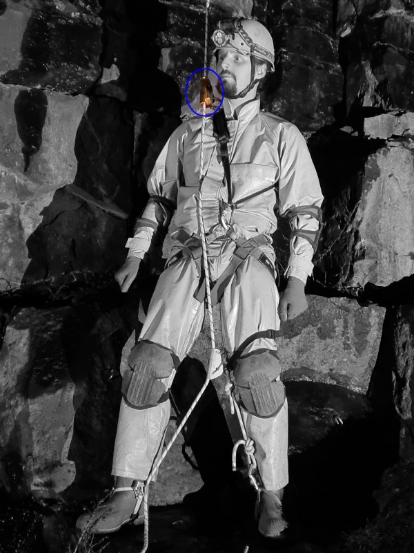

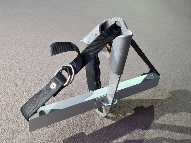
An essential part of the inchworm system, and often a part of the hands and feet system, which attaches a handled foot jammer to the feet. The foot jammer is bolted, screwed or tied to the middle of a metal or wooden bar, or webbing tape covered in a plastic tube, wide enough to put both feet on it, so that the foot jammer sits between the feet. A strap or rope then runs from one end of the bar, through the metal loop at the top of the ascender, and down to the other end of the bar, passing over both feet. This is what causes the foot jammer to be lifted when the feet are raised. The foot jammer must have a single metal loop at the top, on one side of the frame only. If the strap has to pass through holes on both sides of the frame, it will not be possible to get the main rope in or out. Mar-bars were almost always custom made by the person who would end up using them, so there is a great deal of variation, and no standard approach for how to connect them to the ascender. Most designs rely on the square chunky frame of a Jumar brand ascender, which also had a single loop at the top. The name is a shortened version of "Jumar-bar", and comes from the USA, but there seems not to be a British alternative.
The idea of two stirrups for the feet, attached to an ascender, was included in the earliest known clamping jaws ascender, which was created by French inventor Nicolas Grollier de Servière, which he called pincers or pliers ("tenaille" in French). The exact date of its invention is not recorded, but it was during his retirement which began in 1642 and ended with his death in 1689. It is likely to have been shortly after obtaining the 1647 French translation of a book by Galileo Galilei, which inspired the inventor's research into rope access. At that stage, the stirrups were an essential part of the operation of the ascender, which needed to me lifted apart with every movement to release the ascender, which was used for the hands and feet system. In 1725, German engineer Jacob Leupold from the Holy Roman Empire (now Germany) added a separate bar with a pair of stirrups to Claude Perrault's ascenders, and used them with the hands and feet system. This exactly matches the function of the mar-bar. A second one was used for the hands, in the same way as the mar-bar was later said to be usable by cavers.
Many subsequent designs used similar approaches with the hands and feet system. In 1879, German inventor Ed. von Mengden used clamping jaws ascenders with the inchworm system, and used foot stirrups for that. In 1963-1964, the British South Wales Caving Club used the mar-bar approach for their version of the hands and feet system, strapping a bar to their recreation of an existing cable ascender. The ascender attachment and the foot plate was made from welded angle iron on one side, with the other side being made from a bicycle pedal, so that it could rotate to pull a lever on the ascender, allowing it to be disengaged. American Charley Townsend then used a mar-bar for his version of the inchworm system in 1965-1966. This time, it used an actual Jumar ascender, which is what gave the name to the mar-bar. This became popular enough that several designs were subsequently made, fitting whichever ascenders the user had. The bar itself may be made from metal or wood, and the stirrups may be made from rope or welded metal. American arborist Michael David Gardner of Rope Step Inc. had developed a mar-bar by 1992, which was used for the hands and feet system. The specific design is not shown in detail, but appears to be entirely made of fabric webbing, looped around the feet. Arborist books discussed the use of a mar-bar in 1995, for use with the inchworm system, and had probably done so earlier as well. American arborist Paul Sisson had developed his version of the mar-bar by 1999, for use with the hands and feet system, with the same design being used for both the feet and the hands. Each one had two ascenders next to each other, so it could work with either a single rope or doubled rope. The bar was made of fabric webbing, with lengths of plastic piping put over it for the feet or hands to rest on, holding it into shape. By 1999, this design was being sold by American arborist supply company Buckingham Manufacturing.
This history section only covers mar-bars. This article also has a detailed history of many of the other devices and techniques that are used for vertical caving.
A lower jammer, knee jammer or foot jammer which has a footloop or is attached to the foot directly, with some bungee cord pulling the top of the ascender upwards, so that it moves up the rope when the foot is lifted. Used as part of the double bungee or Howie rig variations of rope walking, as well as the another prusiking system. It could also be used for any other system that has a relevant ascender, such as the Texas system and singe system. This is done to remove the need for manually lifting the top of the ascender using a hand, allowing that hand to be used for other purposes. If the bungee cord pulls upwards on the body of a lever cam ascender that is not spring loaded, this can also help the ascender to engage and grip the rope more easily, without needing to be sharply pulled downwards. Also helps to keep the ascender pulled upwards so that it is easier to reach, when it is diconnected from the rope at a rebelay. Usually needs a fairly long bungee to get the required elastic power, so unless a pulley is used to lengthen it in some other way, the ascender will need to be placed quite low on the leg, with the other end of the bungee attached high up on the chest harness. This can make it very difficult to reverse prusik, since the ascender cannot be reached. This also brings a very serious risk of a malfunction causing a fully stretched bungee cord to hurl a metal clip at high speed towards your face, and ascending can prove very difficult if the bungee snaps.
The idea of a floating cam was developed by Kirk MacGregor in Toronto, Canada some time around 1970 (it set a speed record at the start of 1971), using surgical tubing instead of bungee cord to pull an ascender upwards. It was first used for the Howie rig variation of rope walking.
This history section only covers floating cams. This article also has a detailed history of many of the other devices and techniques that are used for vertical caving.
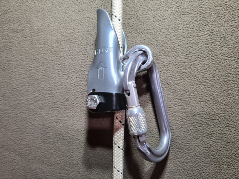
An unusual type of ascender that is not designed to be used for prusiking, and is instead designed to be used as a safety brake when abseiling. However, it gets used for many other purposes, often against the manufacturer's recommendations. It moves when the body of the device is pushed, but not when the device's lever is pulled downwards, known as a lever cam ascender. This is an approach used by much older ascenders, where the weight of the user is what causes the rope to be gripped, instead of a rotating eccentric cam. A shunt traps the rope against the front of the device when the lever is pulled, while almost all traditional lever cam devices trap the rope against the back of the device. Shunts are not designed for caving, and are aimed more at climbing. All attachments must be removed from a shunt in order to remove it from a rope, meaning that it can easily be dropped by mistake at a rebelay. The way to avoid this is to attach a keeper cord the smaller attachment loop, and tie it to yourself, meaning that there is now some string to add to your spaghetti. The device may not function well on muddy ropes, but is intended to work well enough on frozen ropes.
Intended to be used as a safety brake when combined with a descender, and may sometimes be used with a figure of 8 descender, or more rarely with other descenders that leave one hand free to hold the Shunt. It does this much better than most lever cam devices because it uses a smooth bar to contact the rope, and is unlikely to snag the rope unintentionally while descending. This allows a second point of contact to the rope while descending, offering redundancy for safety purposes. For this to work, it requires the body of the device to be pulled downwards to release it while descending, and during an emergency, it requires the presence of mind to release the device so that it can catch the fall, something that is very hard to do when it actually happens. The Shunt is normally attached to the up rope above the descender, but can be used extremely clumsily on the down rope below it instead. Sometimes used for self belaying, since it does not cause as much damage to the rope as most other ascenders would do when catching a fall. In fact, it will slip on the rope a little, adding some shock absorbtion. However, due to the way a fall can pull the Shunt in an unexpected manner, it can end up oriented in a way that causes the lever cam not to engage at all, or to release the rope completely, so that it will not succeed in catching the fall. These issues are far less likely on most dedicated fall arresters. It is important to note that even though it is used to catch falls, as an ascender and as a safety brake, the official Petzl Shunt is not classified as PPE.
In 1904, a lever cam device was patented by Austrian locksmith Michael Gayer, which he called a "clamping sleeve for climbing devices". This was sold as a "climbing device" by F. Turczynski Jagd- und Touristen-Asrüstingen, a mountaineering shop in Vienna, Austria, the city where Austrian mountaineer Karl Prusik lived, run by a member of the Wiener Alpenklub (Vienna Alpine Club), which Karl Prusik was also a member of. The design had a very limited range of rope sizes which it could work with, and used a fiddly bolt and wing nut to close a hinged section around the rope, which would have been very easy to drop by mistake. It was advertised as a fall arrester in Austrian mountaineer E. Fink's Touristen-Vademekum publication in 1904, for self belaying when climbing up or down, for climbers, quarry workers, miners, construction workers, roofers and plumbers. German mountaineer H. Sixt proposed a lever cam device, which German mountaineer Franz Kröner then improved and manufactured in 1911, called a "climbing lock". It was intended to be used in the same way as a Shunt, though its lever worked slightly differently. Austrian mountaineer Karl Prusik claimed in 1931 that the "climbing locks" could not be used when the ropes swelled because they got wet. The Shunt was first sold by Petzl in 1972 as an emergency backup device for use on frozen ropes, and the design has been virtually unchanged since then.
This history section only covers the Shunt. This article also has a detailed history of many of the other devices and techniques that are used for vertical caving.
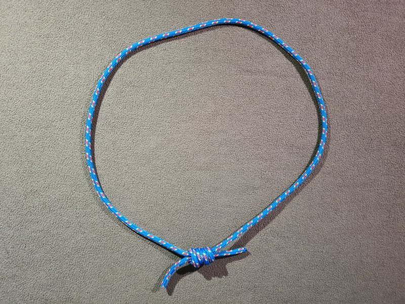
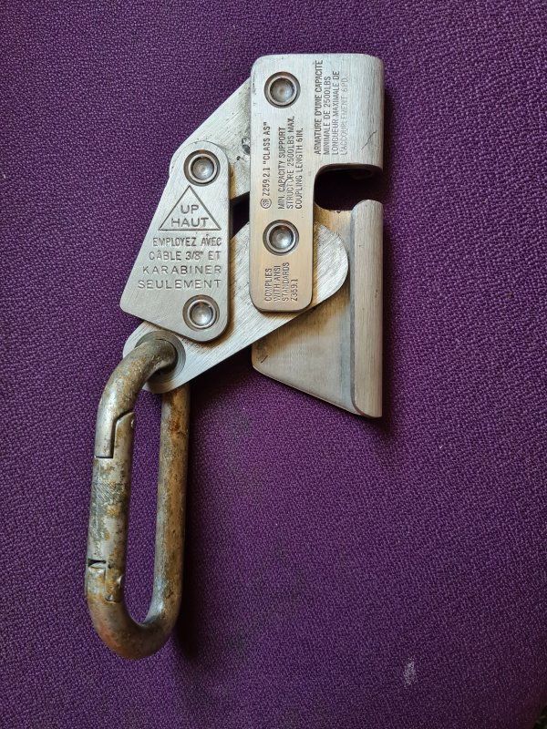
A dedicated device designed to automatically catch an accidental fall, which can be used for self belaying, and is specifically designed to minimise the damage to the rope and the person when catching a fall. Almost all of these are intended for rope access work, and the terms originate there. It is important to note that "rope grab" or "rope clamp" can also refer to ascenders, or anything that grips the rope to allow its position to be adjusted easily, and these are not designed for catching falls. "Fall arrester" can refer to a personal device used to grip a stationary lifeline (known as a backup line in rope access work) when a fall occurs, and this is the type that is most likely to be relevant to vertical caving. These are officially referred to as a "guided-type fall arrester". However, the term can also be used for an automatic belay device that feeds out or retracts a lifeline as long as movements are slow, and stops the lifeline from moving if motion is fast. This type may be known as a "fall arrester block", and is not relevant to vertical caving, but is similar to the devices sometimes installed at indoor climbing walls.
In rope access work, a guided-type fall arrester is typically connected to an attachment point on the chest or back of a full body harness, with the back often being preferred because it holds the body naturally below the attachment point, minimising the amount of flailing when catching a fall. However, these harnesses are not normally used by cavers, so the typical attachment point for a caver would be the D-ring attached to the sit harness. When catching a fall, fall arresters will take some distance to react, start to catch, and actually stop the falling motion. The fall distance will depend on the length of the tether used to attach the fall arrester, since the device could be that distance below the person at the start of the fall, and they will fall until they are that distance below the device, meaning that the tether adds double its length to the distance that the person falls. If the tether changes length during the fall, such as dynamic rope or a shock absorbing tether, that also will be added on to the fall distance. When the rope stretches to absorb the impact of the fall, that stretch amount is also added to the total fall distance. This total fall distance is the height below which the device cannot react fast enough to fully catch a fall before the person hits the ground. With many types of fall arrester, the shortest attachment that can be used is simply a carabiner that is clipped directly to the harness. A locking carabiner is essential, to prevent the device from loading an unlocked carabiner gate. A tether allows rotation, so that no matter whether the person rotates, the device can remain oriented correctly upwards. Cavers are likely to use a cows tail, and will need to have one with a locking carabiner. When using a longer tether, the typical advice is to run the tether over the shoulder so that the device is kept above the attachment point on the harness, reducing the total fall distance, as the tether is already pointing mostly upwards from the harness. This also makes it possible to keep the rope behind the back, out of the way.
Lever cam fall arresters function in the same way as lever cam ascenders, though they normally do not grip much until they are loaded. While it might therefore be assumed that a lever cam ascender could be used for this purpose, ascenders have not been specifically designed and tested for catching falls. Like many lever cam ascenders, some lever cam fall arresters have a spring forcing them to grip the rope, so while they work very well for ascending, they do not move downwards freely and need to be manually pushed downwards when descending. This limits their usefulness.
Fall arresters that are designed to freely allow motion up and down a rope, and only catch when a fall occurs, are typically designed for rope access, where the regulations are different. They are not normally designed to work with the thinner ropes used with caving and climbing. Some are designed to work with the kind of flexible backup lines used in rope access, which is similar to a lifeline used in caving and climbing. Since fall arresters and ascenders are often both sold simply as "rope grabs" is it important to check the device ratings, and see what PPE standards they are designed for, to see if they can actually be trusted as fall arresters. Fall arrester devices are covered by the standards EN 12841-A, relating to common rope access usage, and EN 353-2, which requires even better performance (and normally a thicker rope). Some are designed to be used with a rigid anchor line (often a cable) that is attached at both ends and kept under tension, often seen next to rigid ladders on masts (covered by EN 353-1, an approach only ever seen in caving as a tension traverse, but may be used in climbing for via ferrata). Devices that are designed only for EN 353-2 normally state that they require the thicker ropes, and do not give any details of what happens when used on thinner caving ropes, so they must be assumed to be unable to reliably activate on those ropes.
The vast majority run the rope between a rocker arm and a solid block when the device is hanging downwards from a carabiner, but when pulled downwards using the carabiner, the rope pulls the top edge of the rocker arm, pinching the rope between the bottom of the rocker arm and the solid block. These may be known as rockers, with a few of them using that as the name of the device. The catch is not instant, as it needs the user to be falling faster than the device naturally slides down the rope (which depends on the device's friction against the rope), causing the device to be rotated and pulled downwards. However the catch is usually fast enough not to notice (within 1-2 metres). Often, these will have a locking switch that can prevent them from moving downwards freely, resulting in a faster catch, though this then prevents them from freely moving down the rope when descending. This is an intentional feature intended to prevent high winds pulling rope upwards through the device when working on skyscrapers, a feature cavers are unlikely to care about, but it also makes some devices more useful as an ascender if needed. A couple have a sprung lever that dramatically improves the catching speed, so that they can start to react within just a few centimetres of freefall. Some can also be used as rope access ascenders (EN 12841-B), which may be useful when trying to get back off the rope after the device has caught a fall.
A number of reputable companies make these devices. Rockers with a locking switch include the ISC Rocker, Troll Rocker, SAR Rocker, Beal Monitor, G-Force AC080, Kratos Blocker and Singing Rock Locker. Rockers without a locking switch include the 3M Protecta Viper 2 and Hightec Quantum. (The Camp Lift also uses that design, but it is only rated as an ascender, not for catching falls.) Rockers with a more gently curved rocker arm, and without a locking switch, include the DMM Buddy. Rockers which also push the rope with an extra lever when the carabiner pulls downwards, so it catches more reliably, include the Kong Back-up. It also has a locking switch. Rockers with a sprung lever that pushes the rope into the rocker, so it catches much more quickly, which is lifted out of the way when the device is hanging from the carabiner, include the Camp Goblin and Climbing Technology/Skylotec Easy Speed/Move. Both also have a locking switch. Lever cam devices without a spring include the ISC Mini, 3M Protecta Viper LT, Kratos Olly and Kratos Lorel, of which only the Kratos Olly has a locking switch. Lever cam devices with a spring include the Climbing Technology/Skylotec SKR-2, Kratos Niro, Safetec EN Forcer and Safetec Duck-R. Both Safetec devices use the same lever cam arrangement as the Shunt. The Petzl ASAP uses a toothed wheel, which relies on a governor to lock the wheel when it moves too fast, and can damage the rope's sheath when catching hard falls. There is a version with a locking switch and a version without. The Edelrid Fuse works in a similar way to the Petzl Asap, except that instead of using a toothed wheel, it uses a ridged wedge that slides into place when the wheel detects that the motion is fast enough, but it can also damage the rope's sheath when catching hard falls. It has a locking switch.
These devices all rely on moving parts that may not function as well when muddy, and they are required to include a notice saying something like "high or low temperatures, humidity, rain, ice, oil or dust/dirt can negatively impact the performance of the device and the ropes". Some must only be used on very clean ropes. Part of the testing procedure requires them to work on a wet rope, but they may take a little longer to catch. Some may only work on vertical ropes. Some may not work well on dynamic ropes (for example, the Edelrid Fuse has been tested and failed to catch with common dynamic ropes), and may repeatedly engage and disengage due to bounce. Most require specific carabiner designs, typically an oval locking carabiner, with steel being suggested or required. Most must not be held during a fall, with the Petzl ASAP and Edelrid Fuse being the only exceptions. The Kong Back-up has a known failure if the carabiner rotates on top of the device during a fall. The Petzl ASAP and DMM Buddy explicitly state that they will only work on clean ropes (rather than saying that the function may be reduced), so they are not at all suitable for caving. The Petzl ASAP and Edelrid Fuse catch falls so abruptly that they require a special shock absorbing tether or rope, and therefore cannot be used with a cows tail. The tether needs to be replaced immediately if it activates when a fall is caught, meaning that it can only be used for a single fall. Without a shock absorbing tether, the Edelrid Fuse has been shown to catch falls so hard that it reaches the potential injury level, and can sever the sheath of the rope. The results with the Petzl ASAP are similar. Others may intentionally slip a little when catching severe falls, in order to reduce the force seen by the user, and shock absorbing tethers are optional. The Kratos Blocker does not state whether it is certified as an ascender or fall arrester under EN 12841, but is certified as a fall arrester under EN 353-2. The Troll Rocker, 3M Protecta Viper 2, DMM Buddy, ISC Mini, 3M Protecta Viper LT, Kratos Niro, Kratos Olly and Kratos Lorel are only certified under EN 353-2, which explains their thicker rope requirements. The Safetec En Forcer and Safetec Duck-R are only rated under EN 12841-A, but still require thicker ropes. The Camp Goblin, Petzl ASAP and Edelrid Fuse can work on slightly thinner ropes than the other designs, with all being certified for use with 10 mm rope, but for high performance, they need the same thicker rope as most of the others. The Camp Goblin, Kong Back-Up and Climbing Technology/Skylotec Easy Speed/Move are also rated for use as ascenders. The author of this website cannot make any recommendations, but the Camp Goblin is the only device mentioned here that is certified for use with the 10 mm ropes common in British caving, while not having some other severe limitation. If it helps, Up and Under say that they can order them for you in Britain, since rope access suppliers may have limitations as to whether they can supply them. (There are also the Taz LOV2 and LOV3, which can also be used as a belay device and descender, and are sometimes recommended, but they do not run freely down the rope, so they do not serve the desired purpose. Many other devices, such as the Rock Exotica Silent Partner, Wild Country Revo and AlternativeCurrent Sulu Go have similar limitations.)
In personal testing, the sprung lever of the Camp Goblin improves the catching speed from about 1.6 metres of freefall without the sprung lever (like a basic rocker device) before it begins to catch the fall, to just 5-10 cm of freefall before it begins to catch the fall, a truly impressive improvement. As a result, its performance is far better than many other devices. It may then take another 30-40 cm to slow and stop the fall, like many other rocker devices. Meanwhile its locking switch (which is intended to switch it into ascender mode) causes it to need the weight of about 7 metres of rope below the device before it will slide upwards, which is a significant limitation when used that way. Cavers are unlikely to use it with the locking switch engaged, but it is much worse than an actual ascender, and a significant amount of bottom weighting would be required.
It should be noted that many of these devices are copied by brands without any reputation, sold on major online shopping sites (particularly Amazon and eBay), and are often said to work with much thinner ropes, normally claimed to be useful for climbing. The Rocker is by far the most common design copied this way, often without the locking switch. Many of these copies have falsified ratings stamped on them, and often have mistakes in the certification logos. Some may simply be labelled as complying with EN 567, which means they are only rated as ascenders, EN 341 or EN 12841-C, which means they are only rated as descenders, EN 358, which means they are only rated as belay belts or tethers, or EN 12275, which means they are rated as carabiners (!), even though the accompanying images and text may pretend that they can be used to catch falls. They may even have YouTube videos from people claiming to have used them that way, but just because somebody else risked their life with an uncertified knockoff brand, or got paid to pretend that they did, doesn't mean you should; you will never know until the moment it fails to catch you, by which time it is too late. If the manufacturer of a device does not trust their device enough to certify it for catching falls, then it should not be trusted for catching falls. The author of this website urges you to purchase only reputable brands, from trustworthy suppliers, and use them with appropriate ropes. Your life depends on it. If a brand is only ever sold online, not in dedicated physical shops, it is almost certainly not reputable enough.
The GrandWall Equipment uAscend earns a specal mention here, since some climbers recommend it for this purpose, and it is a very basic rocker without a locking switch, so it looks like it should be suitable. It is certified as a fall arrester under EN 353-2 and the Canadian manufacturer's website says that it is an ascender that can be used with 8-12 mm rope, as a rope grab for limited mountaineering applications. However, the website and marketing is hugely misleading, as the device is only rated as a fall arrester when used with 12 mm rope (not 8-11 mm rope), which nobody ever uses for mountaineering. The manufacturer does not state this on their website, and the device stamp says "ROPE 8-12mm" instead of 12 mm, which is not compatible with the EN 353-2 requirements. It does not move downwards freely on a rope, since it has a spring causing it to lock on the rope, so it is not useful for the situations where it would be needed. The device is not rated as an ascender at all, no matter what the manufacturer claims on their website, since it only has a single certification, and that is not as an ascender. The manufacturer does not trust their own device as a fall arrester, even though they certified it as one, as they say that it needs its own backup device. This type of misleading marketing is both shameful and downright dangerous, and really, any manufacturer that acts this way should not be trusted. Other markings on their device have mixed up the terms when specifying the minimum breaking strength, which suggests that the manufacturing organisation does not understand what they are writing, a mistake which is most common with knockoff brands. The device has been tested and it broke below 6 kN, while a device needs to cope with 15 kN static loading to pass the EN 353-2 certification testing, which suggests that it could never have been properly certified for EN 353-2, with any rope diameter. This device should be treated like any other knockoff brand, and avoided.
The AlternativeCurrent Sulu Go also earns a specal mention, since it is one of the very few devices that claims to be able to catch climbing falls on 6-11 mm rope, which sounds useful. The device uses a unique plate design that squashes the rope when a lever is pulled, with the same underlying function as a lever cam ascender. However, in order to make sure it catches, the lever needs a spring to force it to push against the rope, which means the rope sometimes does not pull through the device when climbing up, and the device does not reliably run freely down the rope, though it may do so sometimes when climbing down slowly enough, on a fast rope. In addition, the manufacturer has not certified its use as a fall arrester. It is certified as a belay device and ascender, and while the manufacturer claims it is usable for catching climbing falls, it has never been properly certified for that use, according to any standard testing. The claimed certification for self belaying (described as "top rope solo") is not a real certification, and it did not pass the complete set of EN 12841-A tests. That means that it is not good enough to be certified as a fall arrester, no matter what the manufacturer tries to claim, and therefore is not trustworthy as a self belaying device for "top rope solo" or anything else. The manufacturer does not state which parts of EN 12841-A they failed to follow, and instead states that they followed "part of the EN 12841 A testing procedures". Perhaps they just followed the part where the device is connected to a rope at the start of the tests, or perhaps they just did the 5 kg tests but not the 100 kg tests. Without a full statement of the testing procedure they followed, it is impossible to know, and it is therefore impossible to know what valid fall arrester usage could make it fail. The device also has not been certified for use as a descender, in spite of frequently being described as suitable for that purpose, and is described by the manufacturer as having the potential to overheat when used as a descender, which could damage the rope. The device is repeatedly stated as needing an additional shock absorber when used with static ropes, even when being used as an ascender! As with many devices, the manufacturer warns that its operation can be affected by dust and mud. It relies on a lot of moving parts, which could fail to operate in muddy conditions. This device absolutely cannot be recommended for caving, for all of these reasons.
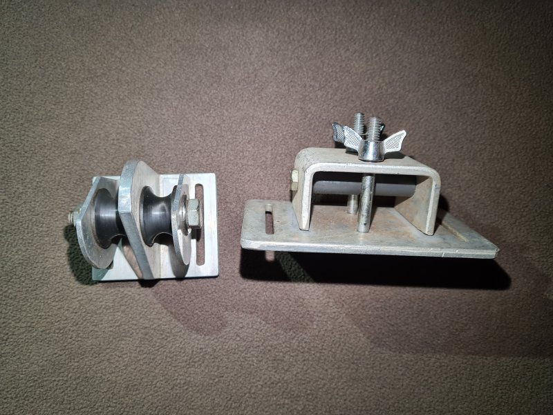

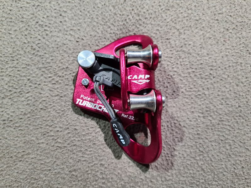
A pulley that is normally attached to the chest harness. The up rope normally passes through it, which forces the chest to remain close to the rope, resulting in an upright stance. This is used for prusiking, and is an essential part of most variations of rope walking, the Mitchell system and the Gossett system variation of the Jumar system, and an optional part of the another prusiking system. It could in theory also be used with the frog system too, but it is awkward to get past rebelays and deviations, so it is almost never used with the frog system. With the Mitchell system, the footloop for the top jammer runs through the chest roller, so the chest roller must have a second pulley for that purpose. With the Gossett system, the footloops for both top jammers run through the chest roller, while the up rope does not, so the chest roller must have a second pulley for that purpose. For rope walking and the Mitchell system, the chest roller should be positioned below the quick attachment safety or top jammer, and above the knee jammer or lower jammer. For the Gossett system, the chest roller should be positioned at waist level below both top jammers, attached to the sit harness. Chest rollers rely on small pulleys to reduce friction, and are prone to becoming clogged with mud, which limits their use in caving. Chest rollers are almost unobtainable in Europe (which is why there is only a stock image of a modern version). Online sales seem not to exist, and the companies that make them seem to do so in very limited production runs, selling directly to groups of interested customers. Presumably within the USA caving communities where they are used, they are only sold on through private channels.
Before chest rollers, the ropes were pulled behind whatever was being used as a chest harness, first proposed by Austrian mountaineer Karl Prusik, published in 1931. After that there were just carabiners, which the ropes ran through, still creating a lot of friction. The first time these were known to be mentioned is in French caver Henry P. Guérin's 1944 book "Spéléologie, manuel technique; Le matériel et son emploi Les explorations", where they were used with the two-knot version of the Gérard Alpine technique, where they were attached to a belay belt instead of a chest harness. These were probably first used with a chest harness at some point during the 1960s, and were still in use by 1967 when the Mitchell system was developed. They continued to be regularly used until chest rollers became more common. After that were pulleys attached to the chest harness. American Keith Wilson created a chest roller (originally called "wheels") in 1969, which was first used with the Mitchell system. Various different designs were then used, often home made. These developed into commercial chest rollers in 1976, with the release of the American BlueWater chest box. The Gossett Ascender Block, intended for either the Gossett system or the Mitchell system, was created in 1977 by American caver Jim Gossett. The single pulley Simmon's Roller, intended for use with rope walking, was created by American cavers Ron Simmons and Ward Foeller in 1979, using the modified case of a Gibbs ascender.
This history section only covers chest rollers. This article also has a detailed history of many of the other devices and techniques that are used for vertical caving.
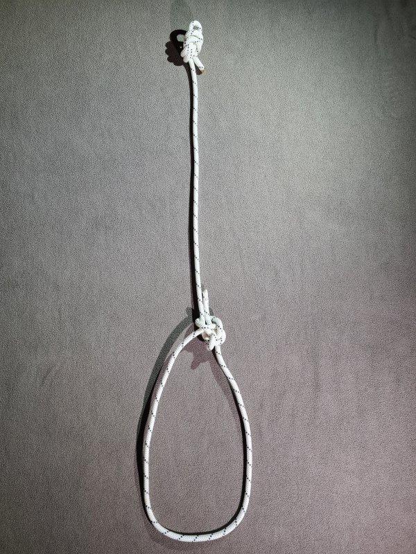
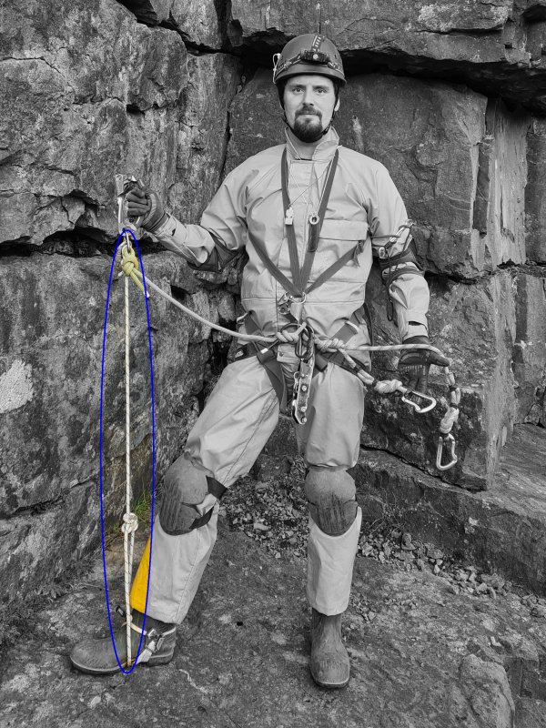
A loop of webbing tape or car inner tube (known as a "snoopy loop" in the scuba diving and cave diving world) which is wrapped aroung the ankle and footloop, holding the footloop in place so that it does not slip off the foot accidentally. Sometimes suggested as a load bearing strap to keep you attached to the rope via a footloop if the upper ascenders disconnect from the rope, and the footloop ascender is all that is left - a situation which should never be allowed to happen in the first place! It would also leave you helplessly hanging upside down by your feet, unable to recover, so is not particularly useful for that purpose anyway. Not normally used with Alpine rigging, since it makes several manoeuvres very awkward, and for this reason they are very rarely seen in Britain. Prevents the use of both feet in the same footloop. The term is rarely used in Britain, and will generally get you funny looks. The term comes from the USA, but there seems not to be a British alternative.
Chicken loops were used soon after 1953 by American cavers, and an improvement to them was described by American caver Daniel Hartline in 1967, for use with prusik loops. Initially, they were tied to the footloop, but by 1969, cavers were using footloops with a chicken loop sewn to them. The term was already well in use by 1973. The term comes from the idea that only someone who is afraid (chicken) would bother to add a strap for safety - a notion that was soon replaced with the idea that safety cords are actually a good idea. Once safety cords became common, it was no longer necessary for a chicken loop to be load bearing, but having chicken loops sewn to a footloop remained very common in American caving for several decades. They were progressively demoted to being just a convenience that could be used with indestructible rope technique. The term later appeared in other sports such as kite surfing, mocking anybody who needed an escape device from their kite in order to avoid dying as being "chicken", because it is apparently a bad thing to want to live.
This history section only covers chicken loops. This article also has a detailed history of many of the other devices and techniques that are used for vertical caving.
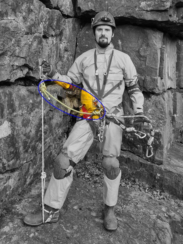
A tether connecting the top jammer, lower jammer or knee jammer to the D-ring. Serves as a safety connection to the rope if the chest jammer, lower jammer or chest roller is disconnected (depending on which prusiking system is being used). Sometimes made from the same piece of rope as the footloop. Sometimes connected part way down the footloop instead of being connected directly to the top jammer, common with the Plummer system. Sometimes a carabiner is added to the end, allowing it to be used as a third cows tail. Sometimes the cows tails are used as safety cords, but that then makes it impossible to use them safely as actual cows tails, so that approach only tends to be used in places where indestructible rope technique is used. It is also used in some parts of France, leaving only one cows tail to use as an actual cows tail. Not to be confused with bungee cord, which can also be called shock cord.
The idea of a safety connection to a first ascender was first devised by German inventor Ed. von Mengden in 1878 for use with his ascenders with the hands and feet system. In 1920, French exterior decorator Antoine Joseph Marius "Paul Cans" Barthelemy created two safety cords between an ascender and a chest harness and sit harness, for his development of rope walking. This idea was repeated by French mountaineer E. Gérard in 1928 for use with the Gérard Alpine technique, connecting a prusik loop to a chest harness. The use of a safe connection to two ascenders at once happened by chance as a result of the development of the fourth sling variation of the frog system, by American caver Dan Bloxsom in 1955. British cavers from the South Wales Caving Club, including John Victor Osborne, added a safety cord to two ascenders when developing their version of the hands and feet system in 1963-1964. Only one was intended for safety and to allow resting. The second safety cord was intended to catch the ascender if it was dropped, but it also would have served a safety purpose if the first ascender failed. The idea of adding a safety cord from an ascender to either the chest harness or a sit harness had re-emerged in the USA by 1965 when the Wisconsin system development started by Dick Boyd, Carl Poster and Bob Olmstead. The idea of using an intentional safety cord to connect to a second ascender to allow a redundant safety system was developed in America by cavers Charles Gibbs and Cleveland Grotto members including Warwick Doll and Lee Watson, some time around 1966, but may have existed as an idea before then. Robert "Bob" Thrun describes using them with prusik loops in Prusiking, 1973. A safety cord was used to a second ascender in the frog system and the UBSS system variation of the Jumar system by the University of Bristol Spelaeological Society during an expedition to Slovenia in 1972. The idea of a safety cord being used to connect to a second ascender was then adoped into the re-developed frog system by French cavers Jean Claude Dobrilla and Georges Marbach, who wrote about it in the first edition of Techniques de la Spéléologie Alpine in 1973. At that time, it was probably adopted into most other prusiking systems as well.
This history section only covers safety cords. This article also has a detailed history of many of the other devices and techniques that are used for vertical caving.
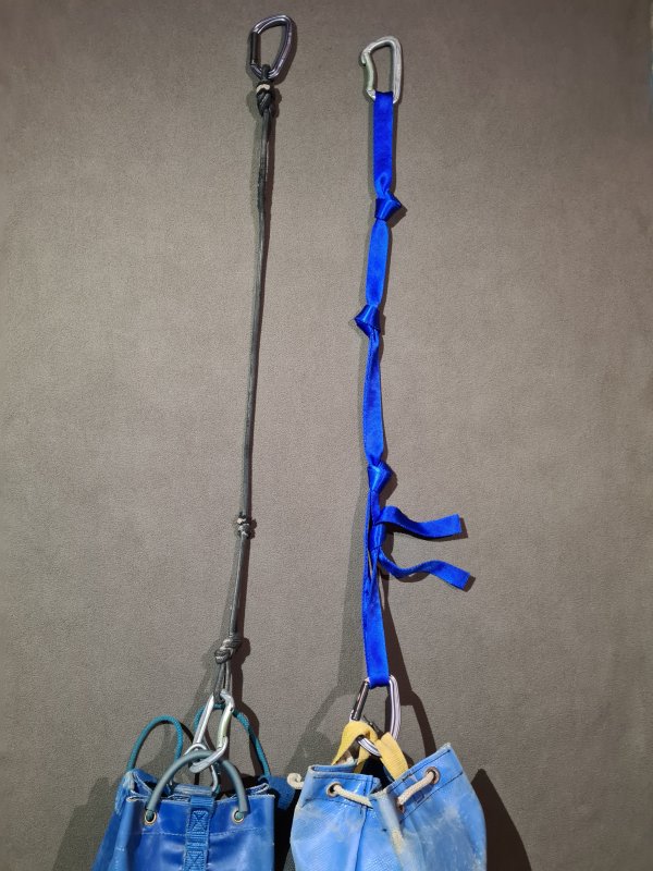
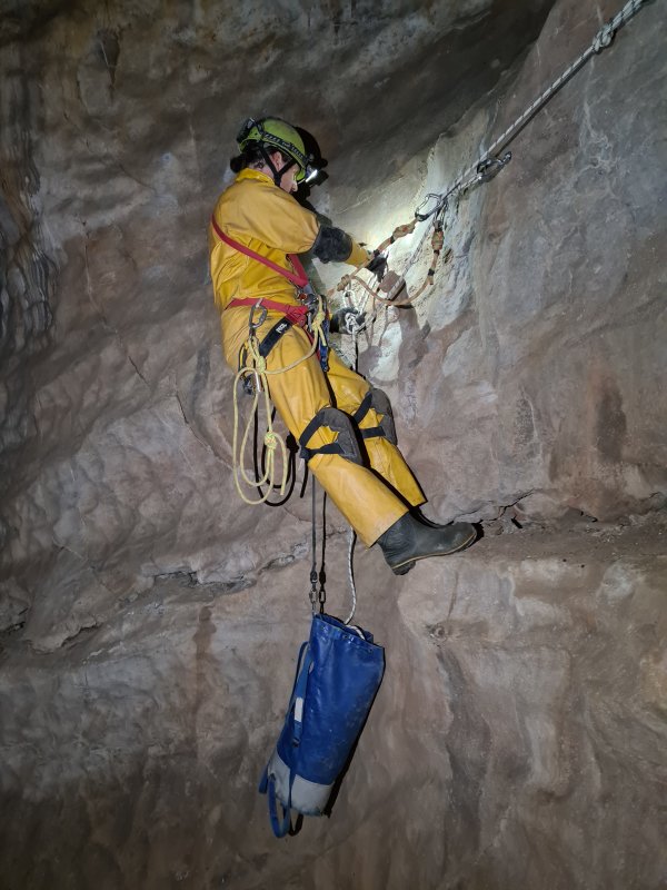
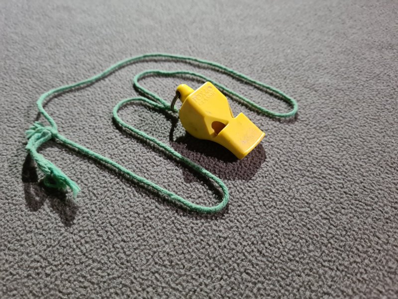
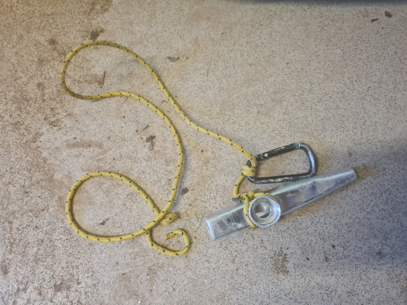

A wireless (or historically wired) electronic device that can allow communication with others on the same pitch, particularly useful with extremely large pitches, where the length of the hang is so large, or the pitch is so noisy, that even a whistle cannot be reliably heard. This is important to allow cavers to let each other know when they can use the rope, to give instructions to a belayer or winch operator, or to call for help.
Current devices rely on wireless radio signals, and do not rely on external service providers, so they can be used in situations where there are no external phone or radio services, such as in a cave. Since the rock blocks high frequency radio signals used by almost all radio devices, there are not many devices that can work through the rock itself. The dedicated cave radios generally require physical contact with the rock to use it as an antenna, such as a Cave-Link, or a conductor, such as with the single wire earth-return telephone ("France Phone"). This is not useful when hanging on a rope. Two wire telephones can - and have - been used, but this means trailing a wire down the pitch, which will then tangle around everything, and create its own spaghetti. Magnetic induction antennae can send low frequency signals through the rock, but even a small loop antenna is larger than cavers can carry conveniently. As a result, the only viable option is to use regular walkie talkie radios to communicate. These can only be used via line of sight, meaning that the radios must be able to see each other in order to communicate, as the high frequency signals cannot bend around corners very well. It is extremely rare to see these in use with British caving, since the pitches are not normally big enough to need it. However, they might be used by rescue teams, or during expeditions.
As with almost all other caving equipment, designs need to be rugged enough to survive in a cave, with some manufacturers making rugged models designed for remote hiking. They also must have a way of being securely attached, to avoid dropping them, which might be a keeper cord or tether. Rescue teams may use designs with an external speaker and microphone that can be clipped to the shoulder, so that the main device can be tucked away, and only a more easily replaced item placed in a vulnerable position.
This section concentrates on communication systems used for pitches, and does not cover radio systems for caving in general. A "talking machine" telephone is thought to have been used for the first time underground during the 1880 re-exploration of the British Lamb Leer Cavern by miner Andrew Lyons. It is not known whether this was a very early prototype electrical telephone, or a mechanical acoustic telephone (basically a tin can string telephone but with a much better diaphragm). He also carried a revolver, so that he could use it to signal the winch operators if the talking machine failed. This is of course standard vertical caving equipment in some regions, particularly Texas. By 1882, electrical telephones were installed in Oak and Manver's collieries in South Yorkshire, Britain. In 1889, French caver Édouard-Alfred Martel and his cousin Gabriel Gaupillat started using a telephone to communicate with belayers, in the French cave Abime de Rabanel. These were both fairly minimal systems where cavers could just talk to the other telephone user, not part of the regular telephone system. They required a telephone wire. Édouard-Alfred Martel's telephone was just 8 cm in diameter, weighed 480 grams, and could work with up to 400 metres of wire. It was especially useful on pitches of over 100 metres in height. Even though the walkie talkie was invented in 1937, they were still fairly expensive and bulky, until transistors started being more regularly used during the mid 1950s. It was still normal for cavers to use wired telephone cables for big pitches in the 1950s, and wired telephones were used during the British expedition to Grotta di Monte Cucco in Italy in 1969 to communicate on a pitch, and to Ghar Parau in Iran in 1972 to communicate with the surface. It was only during the 1970s and 1980s that walkie talkies would have been commonly available for use by cavers. It is not known when walkie talkies were first used underground, but British caver Sid Perou used them to communicate with assistants while photographing large chambers in the Gouffre de la Pierre-Saint-Martin, in France/Spain, in 1972. British cavers Jerry Wooldridge and Andy Eavis used them to communicate with photographic models Dave Checkley, Martyn Farr and two others in 1984 in Sarawak Chamber, Lubang Nasib Bagus, Gunung Mulu National Park, Sarawak, Malaysia. It is even less obvious when they were first used for vertical caving.
This history section only covers walkie talkies and telephones. This article also has a detailed history of many of the other devices and techniques that are used for vertical caving.
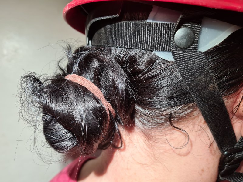
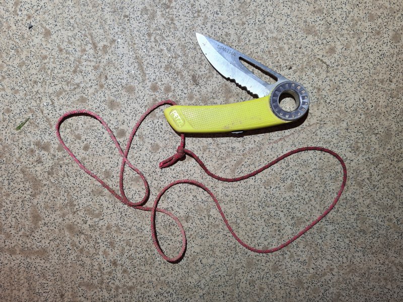
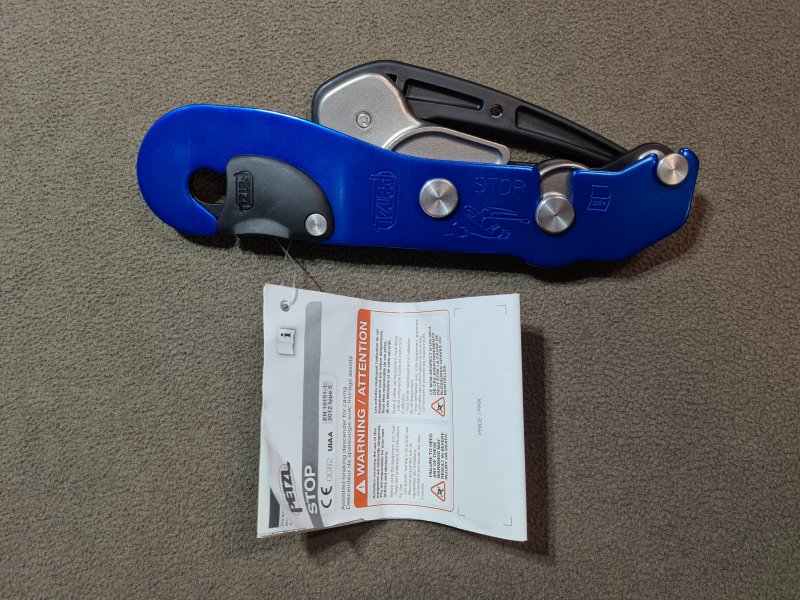
Personal protective equipment. Hardware that has been rated for use in hazardous situations (such as working at heights), to prevent injury. The rating may specify that it can be used for activities such as caving, but might not meet the requirements for rope access work. The rating will say what the minimum breaking strength (MBS) of the device needs to be, and the device will normally be supplied with details or either its MBS or its working load limit, which may be higher than the PPE rating requires. Often the same equipment could be purchased without being PPE rated, but for PPE rating, it normally must have instructions for how to use and maintain the equipment, and inspect it for safety. You are apparently supposed to read these instructions, and I know you will have read them thoroughly. PPE rated is the only way to go for SRT.
When selecting any equipment for SRT, and the product is rated as PPE according to one of the trusted regulations, it is important to check whether it is made or certified in a country that has PPE standards, and actually enforces them. Less trustworthy manufacturers can falsify PPE ratings, and use low quality materials that make the products unsuitable for use. Just because a product has a PPE rating certification stamp on it does not mean that it actually adheres to that rating. If a product claims to be UIAA certified, you can check if it actually is, using the UIAA website, but there is no equivalent for CE/CEN certification which applies to European products. Certifications may also be falsified by copying the identification numbers from legitimate equipment. Fake PPE ratings, fake certifications, counterfeit products and dangerously misleading product specifications are extremely common on major online shopping sites (particularly Amazon and eBay). Purchase only from trustworthy sources, such as local shops dedicated to caving, climbing and rope access, which will have actually checked that the products are not counterfeit, and will actually have been tested for compliance with the relevant PPE standards that they claim to be compliant with. European, North American and Australasian manufacturers, no matter what country they have their products made in, have to adhere to regulations when stamping a product with a certified PPE symbol, so it is beneficial to purchase brands from those regions. If a product is made and branded in places that are renowned for low quality manufacturing, then you should consider whether or not you can trust them to have followed the PPE testing requirements properly. You literally have to trust your life, and that of your fellow cavers to SRT gear and tackle. Make sure it is worthy of that trust.
The British Standards Institution issued standards (BS 431 and BS 908) for Manila hemp and sisal ropes in 1931, which were updated in 1946. In 1950, the British Mountaineering Council stated that both British standards should apply to mountaineering ropes, and gave further requirements for strengths. Hemp and sisal were grouped with other natural fibre ropes (BS 2052) in 1953. Nylon was then covered (BS 3104) from 1959. The International Climbing and Mountaineering Federation (Union Internationale des Associations d'Alpinisme, UIAA) standards were the first to cover sports like caving, particularly creating safety ratings for ropes from 1960 and safety standards for carabiners since 1965 (UIAA 121), and while not a legal body, this rating was used in many countries around the world, including Britain and other European countries, Canada, the USA and New Zealand (but not Australia). The British Standards Institution standard for hawser laid nylon mountaineering ropes (BS 3104) came into force in 1970, but they never completed their proposed coverage of the other synthetic fibres, or kernmantel ropes. The British Health and Safety at Work etc. Act came into force in 1974. However, this was aimed at working conditions and therefore rope access, rather than caving. The European standards for PPE were adopted in 1989, and came into force from 1992 onwards, where conforming products can be marked with a CE logo and standard number. The British version of that (Personal Protective Equipment at Work Regulations) started to be introduced from 1992 onwards, and came into force from 1993 onwards. However, each different type of PPE product has its own timeline from then onwards, and some items were not PPE rated for several more years. For example, the European rope standards for SRT rope (CEN EN 1891), dynamic rope (CEN EN 892) and carabiners (CEN EN 12275) were created in 1998. These then superseded all the relevant existing British standards. The UIAA also published their UIAA 101 standard for dynamic ropes in 1998, and since 2004, this has been based almost completely on the European standards. The same applies to many of the UIAA's other standards. The UIAA standard UIAA 107 for static ropes was first published in 2013, based on CEN EN 1891. The British UKCA and Northern Irish UKNI ratings are simply a reference to the relevant European standards, and apply from 2021 onwards. As a result, within Europe (and that includes Britain), the standards for most PPE are the same, with different ratings only for the different intended purposes, such as sport or rope access. (Though there are some different requirements for what has to be printed on a product destined for different regions, but that is for the manufacturer and suplier to worry about rather than the caver.)
The situation in the USA is a lot more complicated, since each field has its own regulations that are not based on each other. Ridiculous! We need to develop one universal standard that covers everyone's use cases. UIAA ratings and later voluntary standards covered non-commercial sports like caving since 1960. U.S. Federal Specifications covered rope specifications (TR-605B) since 1963. National Fire Protection Association (NFPA) standards cover the fire service and rescue organisations since 1970, and specifically cover rope working equipment since 1985 (NFPA 1983). Occupational Safety and Health Administration (OSHA) regulations cover rope access work since 1991. American Society for Testing and Materials (ASTM International) voluntary standards cover some aspects of rescue usage since 1999 (ASTM F1956-20 for rescue carabiners, ASTM F2116-01 2001 for static rope for rescue purposes), and rope access work since 2007 (ASTM E2505-07). The American Cordage Institute publish voluntary standards for ropes, starting from 2001. American National Standards Institute (ANSI) standards cover rope access work since 2021 (ANSI/ASSP Z359) as a suggested baseline for OSHA compliance, with the American Cordage Institute specifications used for reference. Some equipment used for caving might be covered by all of those, but this is not a requirement, since there are no mandated standards for caving equipment, so American equipment might have no certifications at all, if it is intended to be sold in the USA and not Europe.
The International Organization for Standardization published their standards for nylon ropes (ISO 1140), polyester ropes (ISO 1141) and Manila hemp ropes (ISO 1181) in 1990. Their standard for rope access work (ISO 22846-1) was created in 2003, and that is used in some countries such as Australia. Australia and New Zealand started to gain their conjoined AS/NZS PPE regulations in the 1990s, many of which are based directly on the European standards, but some of which are even more strict, such as the one covering climbing sit harnesses. Russia started adding its own PPE ratings with various GOST codes in the late 1990s. Eurasian Conformity (EAC) standard TR CU 019/2011 came into force in 2012, covering the Eurasian Customs Union, which consists of Russia and some former Soviet states, and replaced several GOST codes, or referenced them. The Canadian Standards Association (CSA) have their own regulations for rope access work, with CSA Z259.17 from 2021.
This history section only covers PPE. This article also has a detailed history of many of the other devices and techniques that are used for vertical caving.
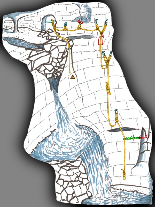
By far the dominant approach used in Europe, and most other parts of the world. Ropes are treated as a resource that should not be wasted. Rub points are avoided wherever possible, though rope rub protection may be needed in rare cases where a rub point cannot be avoided. Traverse lines, rebelays and deviations are used to avoid rub points and other hazards such as water (without creating new hazards, such as a short end). This requires more knowledge of techniques, and rigging can take longer, but typically takes less rope, since anchors can be placed appropriately where they are needed, instead of having to find the best natural some distance away from the pitch. When naturals are used, a sling is typically used to connect to them. Backups are used to provide redundancy or protection when approaching the pitch head. Although passing a knot may be needed in very rare cases, is almost always avoided by joining ropes at rebelays or other convenient points. Alpine rigging uses thinner and more flexible ropes than indestructible rope technique, so Alpine rigging needs fewer people and less effort to carry the ropes through the cave. Typically 10 mm or 10.5 mm rope is used, but 9 mm is often used during exploration, and sometimes during regular caving. European Alpine rigging ropes are made from nylon which can absorb higher shock loads if things go wrong, but cannot cope with so much damage in places where rub points are unavoidable. They bounce more, which exaggerates this effect, and being thin makes both the bounce and the damage more significant. Ropes used for indestructible rope technique are made from polyester which is more abrasion resistant, but cannot absorb shock loads, so they do not offer protection from things going wrong, such as someone falling onto a traverse line, or an anchor failing. With Alpine rigging, cavers can use separate hangs on the same pitch at the same time, and do not have to wait for each other to finish the pitch.
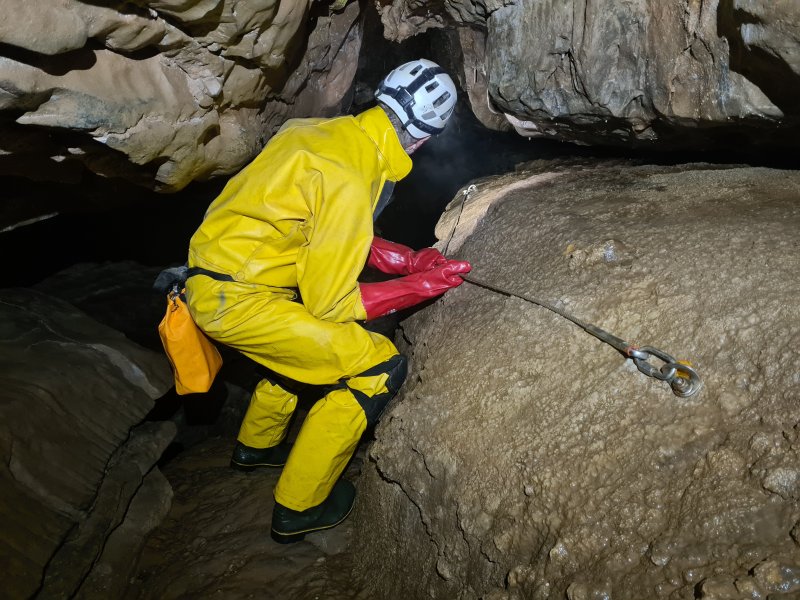
Historically, one of the major uses for ropes was to protect people from drops, and this will have been in use during building work by the Romans, possibly as early as 500 BCE. It is not known if earlier cultures used ropes in that way, but it is quite possible that they would have been used in China. Traverse lines for traversing have been used in mountaineering since its early days, likely to have been during the 1700s or 1800s. Rudamentary traverse lines had been in use for a very long time in caving, with protection added around drops, particularly in showcaves, since the 1800s. French caver Henry P. Guérin shows their use in 1944, using pitons as anchors, for crossing an actual traverse. The same publication shows that ladders might be hung between two attachment points on opposite sides of a pitch, similar to a Y-hang, if they needed to descend the pitch in a position where there was nothing useful to connect the ladder to. Cabled traverse lines appeared in Ogof Ffynnon Ddu in Britain in 1951 (Maypole Series wire traverse), and then a segmented traverse with intermediate anchors made in the same year (Bolt Traverse). At that time, long term traverses and fixed aids often used large diameter expansion bolts. (A fixed cables was being used in Gough's Cave in Britain by 1907, to help show cave visitors to climb a steep slope, but this was not a traverse.) In 1959, American cavers John Patton and Gunther Schmidt used a pulley instead of a carabiner to create a deviation-like structure to avoid rub points at the lip of a pitch, resulting in what looked like a Y-hang. This was pulled to such an angle that the deviation tether had to support the full weight of the caver, so it could not be used like a deviation, and since it did not offer redundancy, it could not function as a Y-hang either. Getting past it would need the caver to be able to stand on solid ground, since it would have required too much strength to use it like a normal deviation, but it still needed to be treated like a deviation, unclipping it from the rope to get past it. Using a pulley made this much more laborious, so the suggestion was not to pass it, and instead just manually climb up the wall, using the pulley's tether as a handline. Traverse lines can be seen in American caving pictures from the mid 1960s.
By 1961, British cavers were beginning to see the defficiencies in the knots they used to use, and were starting to move towards the knots that would become important for the future use with SRT and Alpine rigging in Britain. The Wessex Cave Club, whose use of SRT was very limited at that stage, stated that the bowline was particularly prone to slipping with nylon ropes, and the use of a half knot (described as a half hitch) as a stopper knot was recommended. By 1963, they stated that sheet bends were dangerous, and only the single fisherman's knot was acceptable (now replaced with the much safer double fisherman's knot. They described the overhand on a bight as a general purpose knot, that was difficult to untie. They also stated that a bowline was not safe with nylon, and that a double bowline should be used (a knot which is rarely seen now, using two turns instead of one for the initial twist). Their earlier advice of using a stopper knot is the advice that survived. By 1969, the figure of 8 on a bight was being recommended for use.
Alpine rigging was not discussed in vertical caving manuals in 1969, and at that point, the BlueWater polyester ropes that were available had less need for it, as they were more resistant to damage from rub points, as long as large amounts of rope rub protection was used. Cavers, however, needed to be protected from hazards like water and loose rocks, and the indestructible rope technique rigging did not provide any safe approaches there. In 1972, Nick Reckert of the Cambridge University Caving Club wrote about methods and equipment for potholing, much of which had been learned in France. He advised using a double belay in case one fails, but did not say if he was referring to a Y-hang or a backup. However, by 1973, the first edition of Techniques de la Spéléologie Alpine by French cavers Jean Claude Dobrilla and Georges Marbach shows that they had both taken part in developing the initial stages of Alpine rigging. By that year, there were backups, minimal traverse lines and rebelays, as well as the idea of using spits as anchors to avoid rub points and hazards exactly where they were needed. Traverse lines generally did not use intermediate anchors. Y-hangs were only used to hang ladders, not for SRT. The overhand on a bight was almost the only knot used, but the lark's foot and clove hitch were used when rebelaying a lifeline at the top of a ladder. In 1974, American caver Sam Pitthan suggested using a deviation-like structure to avoid rub points at the lip of a pitch, but did so in a way that would cause the deviation to have to support more than the total weight of the caver. It did not function as either a deviation or a Y-hang, as the caver would not be able to temporarily remove it in order to get past it, and was very similar to the approach used by John Patton and Gunther Schmidt 15 years earlier.
By 1977, an SRT manual by Australian caver Neil R. Montgomery shows that a very complete approach also including Y-hangs and deviations was in use in Europe and Australia, though traverse lines would later earn more intermediate anchors. This allowed the more supple and slightly less static European ropes to be used safely. Many of the common knots were in use, but the Y-hang knots and butterfly knot had not yet appeared, though these were added over the subsequent years. In Britain, the developments during the 1970s were pioneered from around 1974 onwards by Mike Meredith, Paul Ramsden, Dave Elliot, Dusty Spenser et al., mostly in Northern England, while in Australia they were pioneered by Neil R. Montgomery et al., with many aspects of them developed throughout Europe. Alpine rigging became the main approach in Britain starting in 1980. Alpine rigging has since been adopted in some parts of the USA since the 1990s too, but there are still very significant parts of the USA where it is not used. In the early 1980s, spit anchor installation and maintainance started to be officially managed by caving councils in Britain. P-hangers were developed in the late 1980s, and they became the normal anchors used in British caves starting from 1991. However, spits were still used for a number of years in various regions. The very occasional use of Abalakov threads in British caves and expeditions will have existed since drills were used around the 1990s (and could have been used before then with star drills), though this will have increased with the introduction of lithium ion drills in 2005. However, at the time of writing (2023), these are only used on a very small scale, such as with fixed handlines or deviations, and not used extensively to rig major potholes. They had been used during the exploration of ice caves and glacier caves, reported as used by British cavers in 2011 (the Abalakov thread was invented by Russian Vitaly Abalakov around 1934), but they remained uncommon in limestone. From around 2020, some French caves started to be prepared using Abalakov threads that were drilled for amarrage souples, with the most notable example being the Gouffre Berger.
This history section only covers alpine rigging. This article also has a detailed history of many of the other devices and techniques that are used for vertical caving.
A variation of Alpine rigging, using thinner ropes, such as 8 mm or 7 mm diameter. Carabiners may be swapped for lightweight maillons, and hangers might be swapped for amarrage souples. This approach is regularly used during expeditions, but is often stated as being suitable for use by experts only. This can produce a 20-25% reduction in equipment weight, but requires rigging to be more careful, and some cavers can find the thinner rope more uncomfortable or intimidating. Many descenders will require a braking carabiner due to the thinner ropes being extremely fast.
Once Alpine rigging had started, by 1973, ultralight rigging happened by accident only because European ropes were sometimes much thinner than expected, since the diameters were not reliable at that time. The approach had the chance to develop intentionally during the 1980s, when European cavers started to use more reliable European ropes, and was more common in Alpine regions than elsewhere. In 1997, French cavers complained that the European rope standards did not initially allow it, so the standards were changed accordingly.
This history section only covers ultralight rigging. This article also has a detailed history of many of the other devices and techniques that are used for vertical caving.
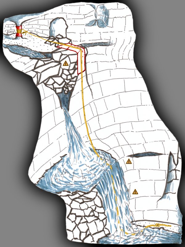
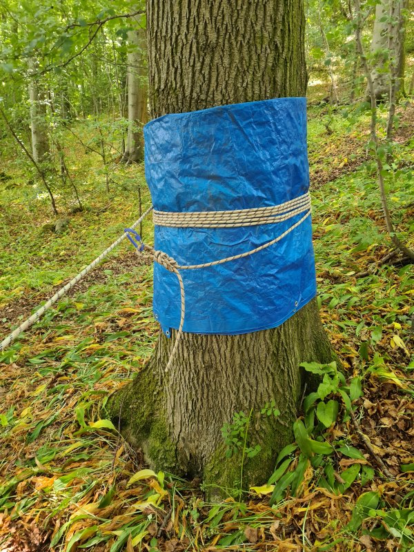
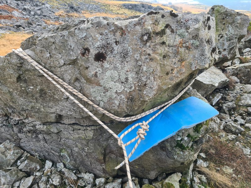
An alternative to Alpine rigging, used in some areas, particularly parts of the USA. These are especially the southeast and midwest USA. Ropes are routinely treated as disposable, and thicker ropes are used to allow more damage from rub points before the rope has to be disposed of. This may be 11 mm, 12 mm, or even 12.5 mm (approximately half inch) rope. Ropes are usually made from harder wearing polyester, to make them more resistant to the damage that they will inevitably receive from rub points. Naturals are generally preferred over anchors, particularly a single natural that is considered particularly indestructible ("bombproof"). The rope is often connected to the natural using a tensionless hitch. The tail of the tensionless hitch is normally clipped to the loaded rope using a single carabiner, but it is also common for a bowline to be threaded around the loaded rope instead to avoid carabiners altogether. The rope is then hung over the edge of the pitch, and it takes whatever route gravity causes it to take down the pitch, using rope rub protectors as needed because of all the rub points that will be encountered on the way.
The theory is that rigging takes less time, and less rope is needed since the rope can go directly from the pitch head to the pitch base. However, extra rope is needed to reach that perfect indestructible natural, and loop the rope around it several times. This approach is used to avoid having to use traverses, rebelays and deviations, which provides simplicity, and removes some of the risks associated with performing manoeuvres. While indestructible rope technique avoids having to modify the cave by adding anchors, it could easily be argued that the cave gets damaged more by all of the rub points, and footprints down the walls. Deep grooves are often visible at rub points where ropes have rubbed for many years (many of these in Britain are from the use of ladders and lifelines). The main benefit of the tensionless hitch, that it preserves the full breaking strength of the rope, is entirely unnecessary, since a knotted rope is already strong enough to allow more than 10 cavers to actively bounce around on the rope at the same time, and is far stronger than any descender or ascender, or the caver that they are attached to. The benefit is immediately wasted by bending the rope over the lip of the pitch, which is often far more severe than a knot, and the motion can also cause it to rub there. Fewer carabiners are needed but more rope rub protectors are needed. According to "Vertical" by Al Warild, the thicker rope and extra length used for reaching and attaching to naturals, means that on average, indestructible rope technique requires nearly twice as much weight of equipment as Alpine rigging. Trips take about the same length of time and energy as with Alpine rigging, but larger teams may be needed to carry the extra equipment.
Hazards on pitches can only be avoided if the rope happens to miss them during the descent, and there are many cases where hazards such as loose boulders and waterfalls simply cannot be avoided. This adds significant risk, and also means that cavers may have to carry around the extra weight of water in their clothing. At least it washes the ropes, and avoids burning them with hot descenders. Since there are no knots to pass, and there is often a very heavy rope below, cavers may prefer to use a rack for abseiling and rope walking for prusiking. The effect of bounce is significantly higher, due to big pitches not being broken up into shorter hangs, and the rope being made even longer by the distance needed to reach naturals. This is counteracted slightly by the thicker ropes, and counteracted even more by selecting ropes with far less stretch and far less shock absorbing capabilities than the European rope standards would allow, and using prusiking systems that produce minimal bounce, such as step systems like rope walking. Even on a long pitch, only one caver at a time can abseil, which adds to the time spent waiting. With prusiking, the only way to allow more than one caver at a time on the rope is to use tandem prusiking, but this makes it far harder to get past a rub point.
Getting over the lip of a pitch is the most difficult part, and deaths have occurred from exhausted cavers being unable to lift a heavy rope up enough to get their ascenders past the lip of a big pitch. This is particularly problematic on tall pitches where there is a lot of rope, or on wet pitches which make the rope heavier, or when using the thick and heavy ropes which are normally used for indestructible rope technique, or when tandem prusiking, or on pitches where there are no rock ledges to stand on while passing the lip. As a result, techniques such as a tail might be used, or an etrier made from a prusik loop connected to the rope just above the lip, with its loop hanging below the lip, giving something to stand on. Many cavers will carry an additional ascender with a footloop that they can attach to the rope above a lip, to provide a foothold exactly when they need it. By having a safety cord attached to it, making it a quick attachment safety, it allows other ascenders to be detatched one by one to get past the lip while maintaining a good number of safe connections to the rope. This problem can be avoided by using Alpine rigging.
While it may be popular in parts of the USA, indestructible rope technique was not originally created there. It is, in essence, the lack of an advance in rigging, beyond the basics that were developed in the very early days of SRT. It is how SRT started. In 1944, French caver Henry P. Guérin depicted only the overhand on a bight knot (and the Prusik knot, chain sinnet, and a variation of the butterfly coil), and although it is not explicitly stated if it was used for rigging, it is almost certainly the knot that was used for that purpose, and presumably had been used by French cavers Henri "Kiki" Brenot and Pierre Chevalier in 1934. Once SRT started to be used in the USA, there were some developments that originated there, such as thicker ropes, harder wearing rope materials, better rope rub protection materials, and the tensionless hitch used for naturals. The tensionless hitch was mentioned by American sailor Clifford Warren Ashley in the Ashley Book Of Knots (#2047) in 1944, using a clove hitch as the final knot. It was used by rope manufacturing companies as a way to test the maximum strength of their ropes. It was not in use by cavers in 1962, and probably started to be used in the 1970s. In 1977, it was shown in an SRT manual by Australian caver Neil R. Montgomery (which discussed Alpine rigging), using a figure of 8 on a bight as the final knot. It was described in 1983 in Nylon Highway as being the "conventional way" in America, and had become well established by then. Some of the rope rub protection developments came in response to serious incidents, such as three separate incidents where a rope snapped while passing over the unprotected sharp lip of Dante's Descent in the USA, presumably in the mid to late 1950s, one of which ended with a caver suffering severe injuries. Another incident that inspired use of better naturals was in 1974 when a large boulder that was used as a natural decided to follow a caver down a pitch in Tennessee, USA, injuring him significantly when it hit him (a similar incident happened in 1981). Another incident which may have inspired the tensionless hitch occurred some time before 1977 when a caver in Puerto Rico was mildly injured when the rope came untied from its only natural as she tried to prusik past the awkward lip of a pitch.
This history section only covers indestructible rope technique. This article also has a detailed history of many of the other devices and techniques that are used for vertical caving.
A way to descend a series of pitches as a pull-through, making it possible to re-ascend them again. The end of the down rope is whipped or tied to a thin cord, using a knot small enough to pass through the anchors or carabiners at the pitch head. The end of the rope may be prepared for this purpose by stitching a short length of thin cord to the end, so that it can be tied with a smaller knot. As the rope is pulled down, it pulls the thin cord up, and back down the other side. The thin cord is then tied into a loop and left in place as a pull-up cord, pulled tight with some rocks to avoid tangling. This can then be repeated on subsequent pitches using the same rope. Although it means taking a longer rope to allow pulling through, in addition to the pull-up cords, it can mean taking less heavy rope in total when multiple pitches are involved. It takes extra time to prepare the cord after each descent. This works out as the lowest weight method of descending multiple pitches, roughly half the total equipment weight of Alpine rigging (in caves where cord technique is possible), and the time taken for setting up the cords is counteracted by the speedy movement due to carrying less equipment. However, it is highly prone to failures and tangles.
Cord technique was first developed by French caver Daniel Martinez in 1972, as an adaptation of a pull-through and pull-up cords.
This history section only covers cord technique. This article also has a detailed history of many of the other devices and techniques that are used for vertical caving.
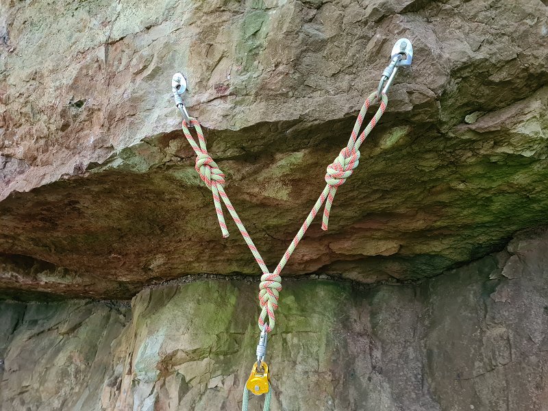
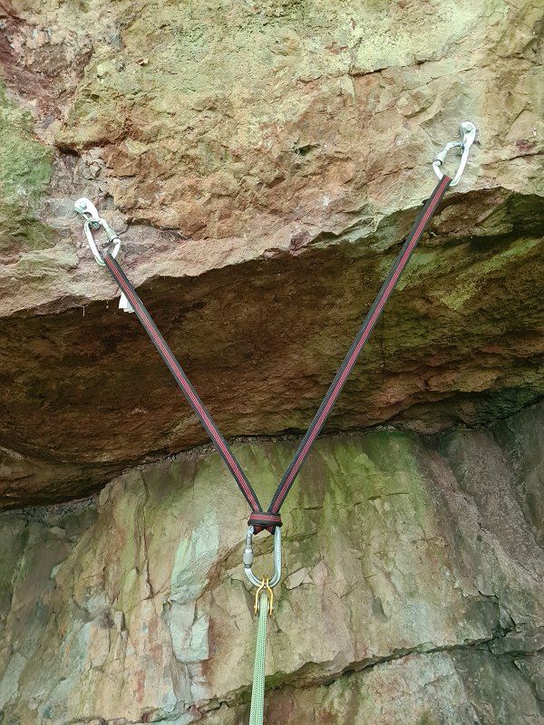
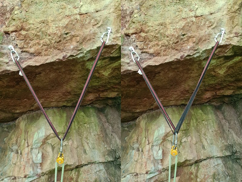
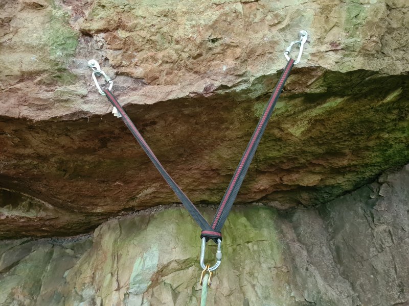
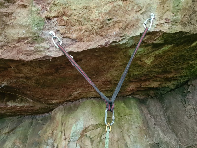
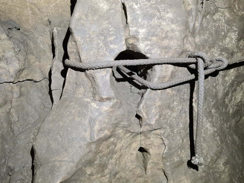
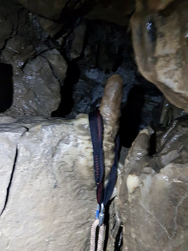
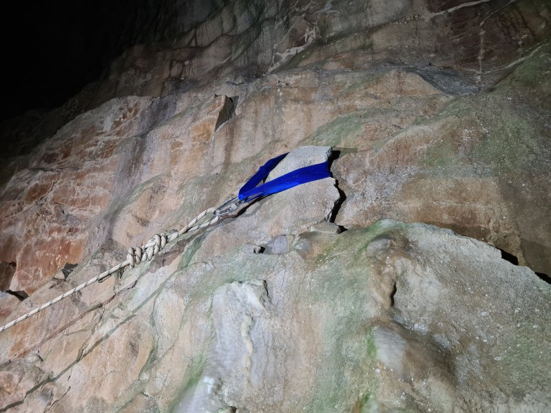
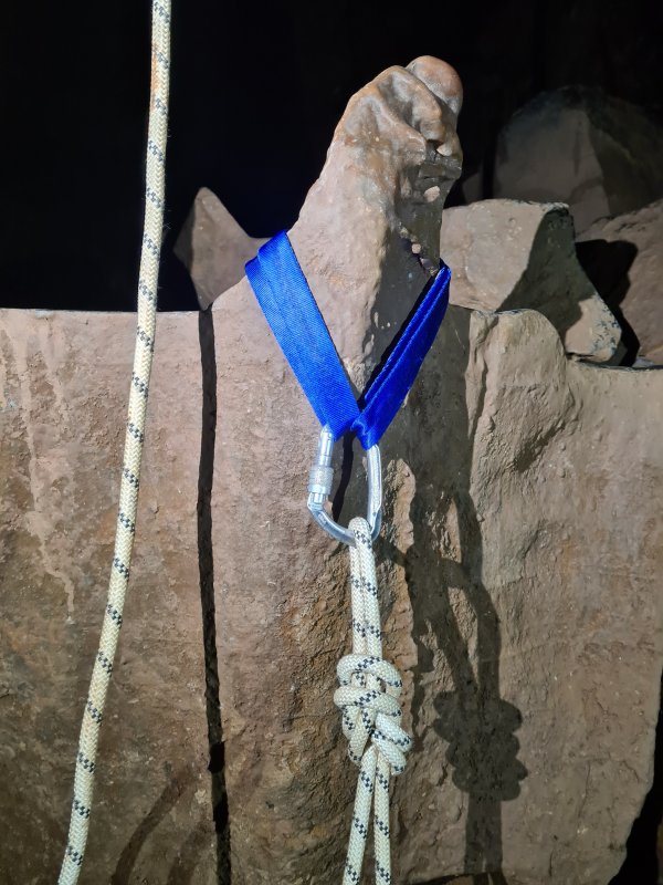
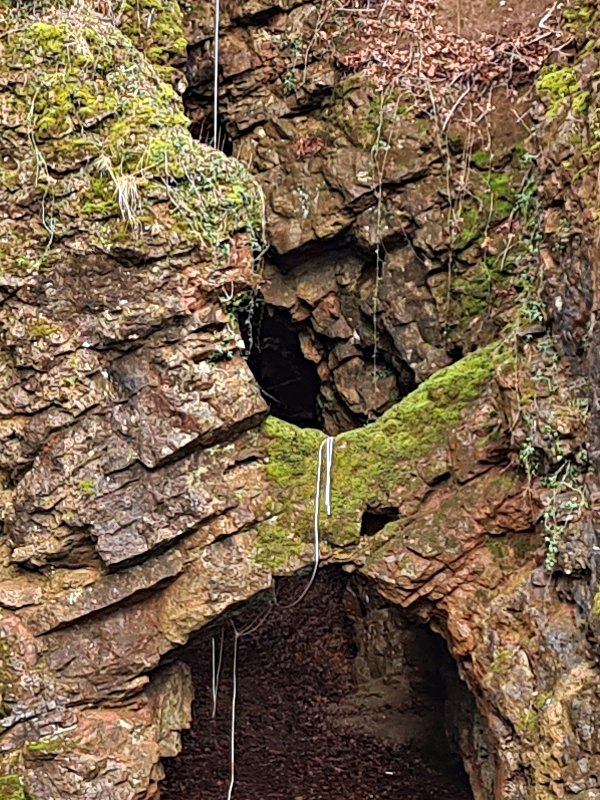
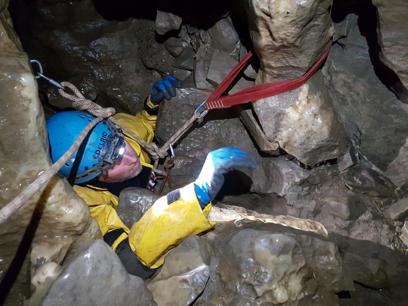
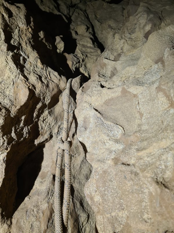
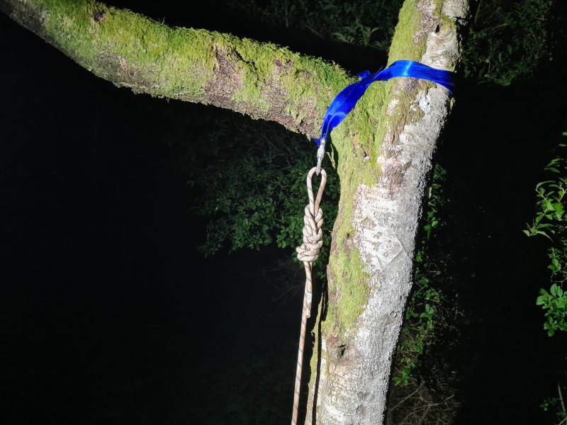
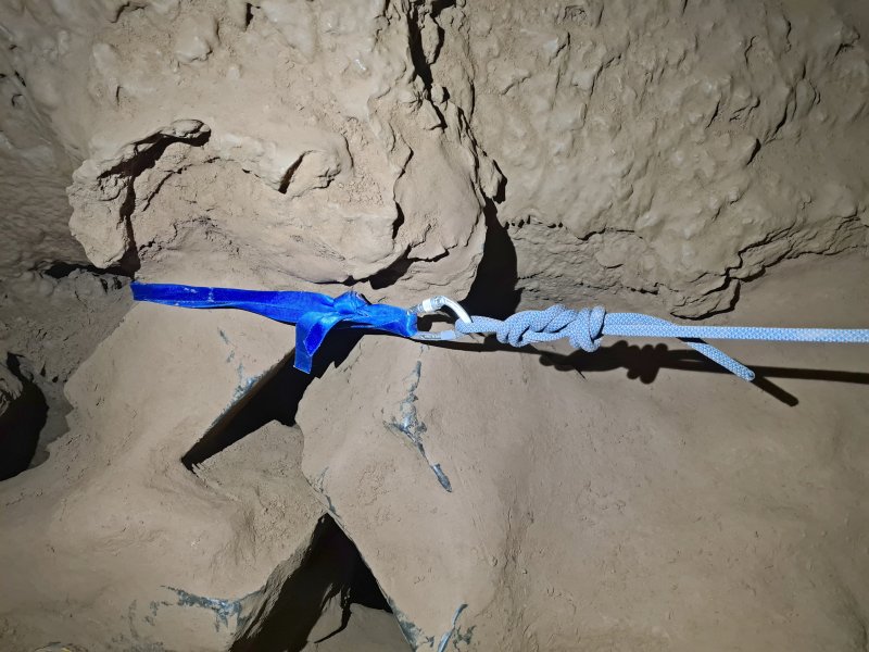
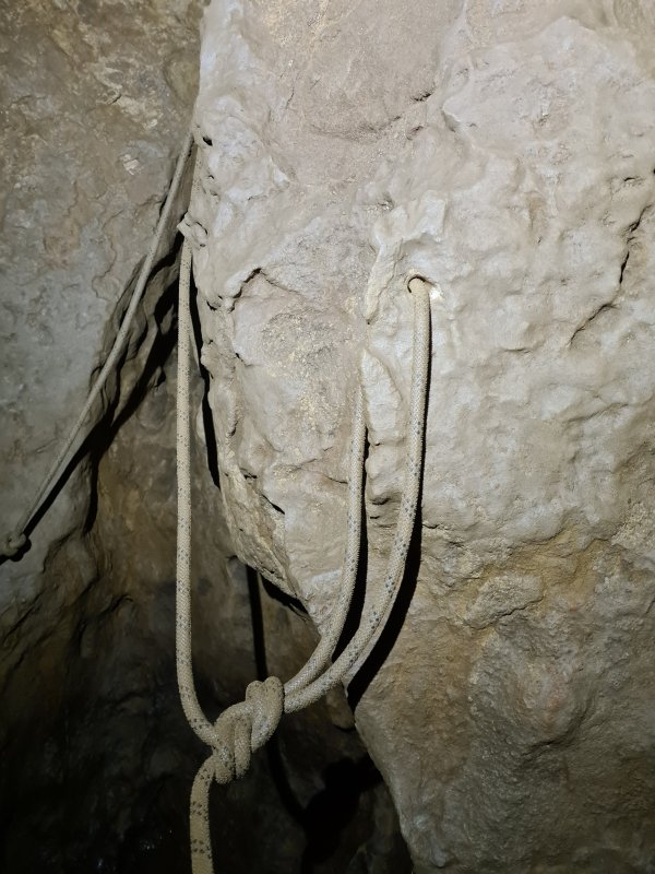
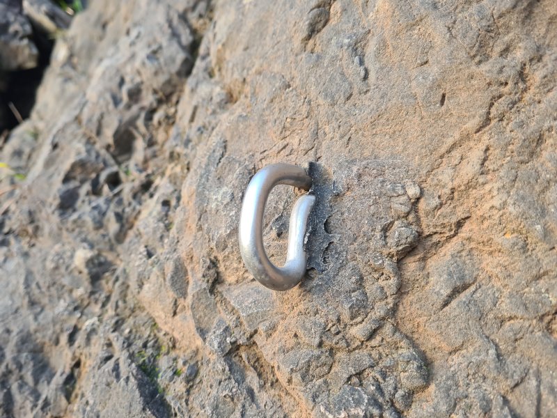
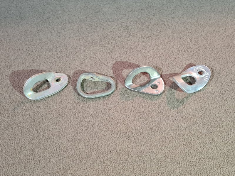
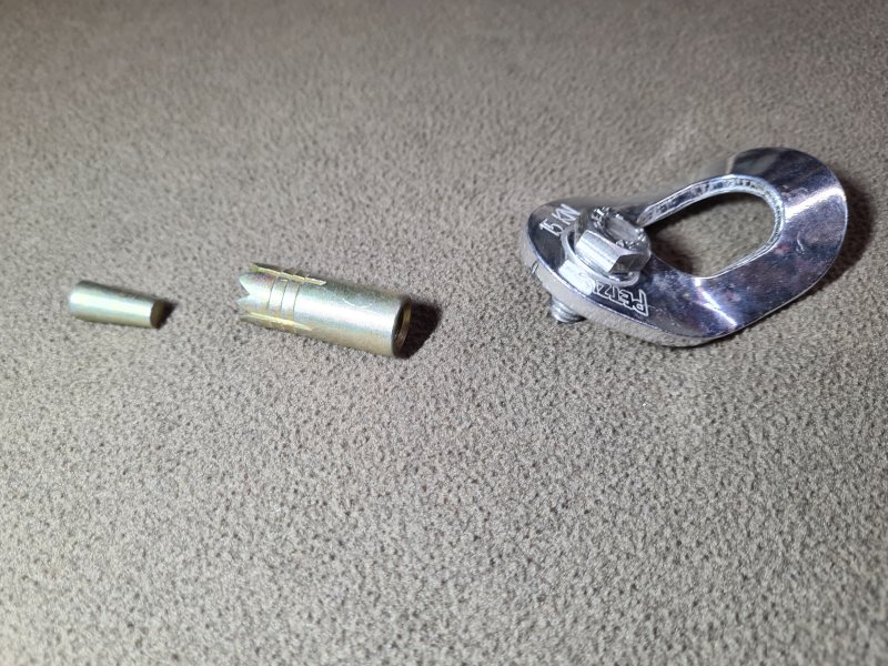
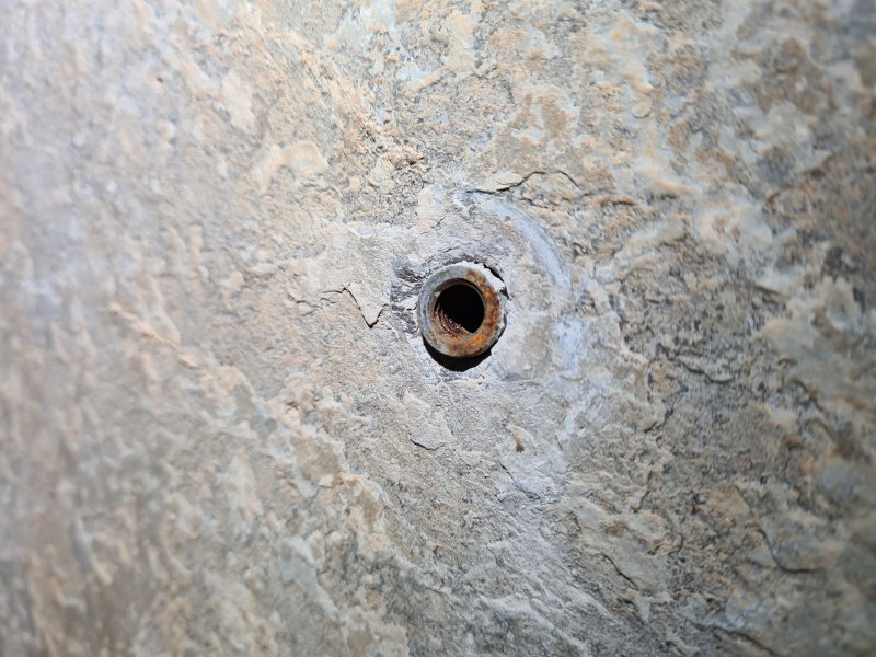
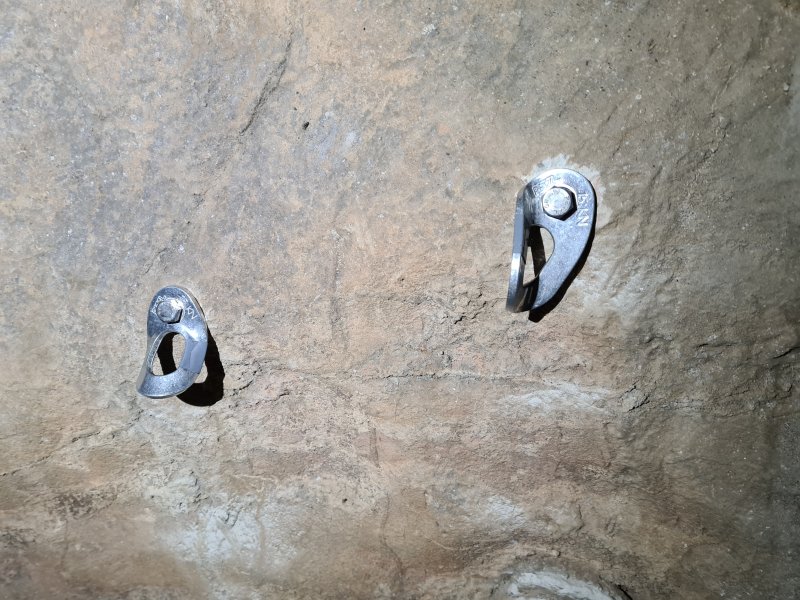
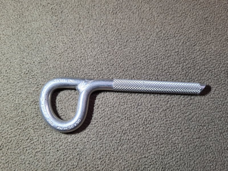
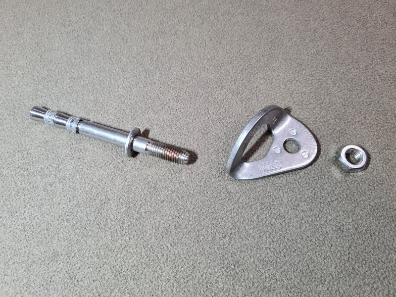

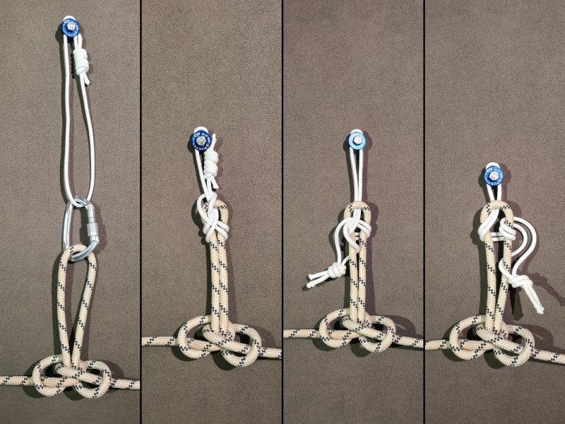
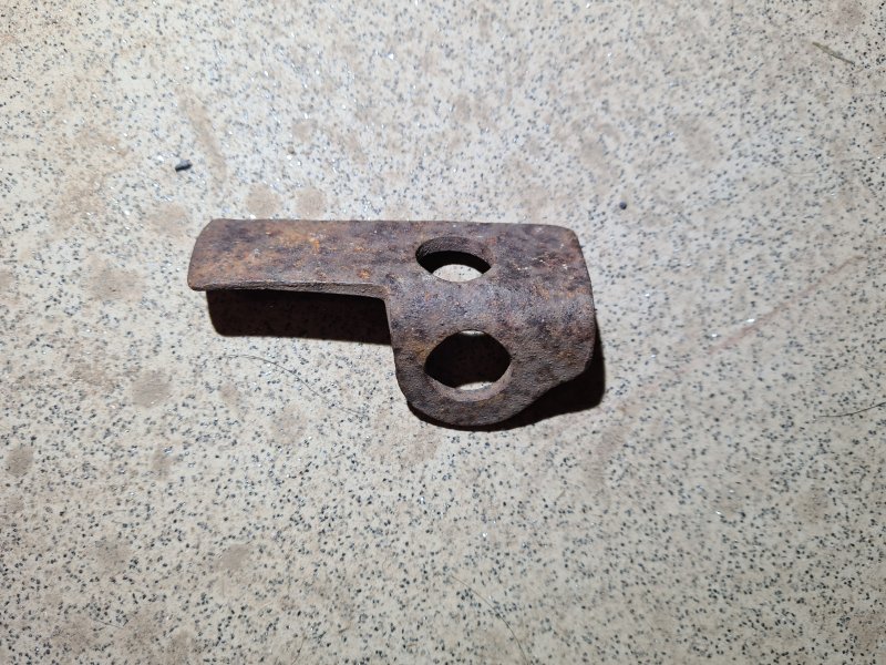
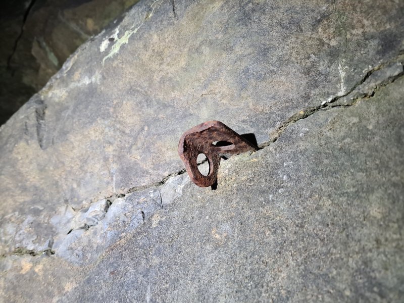
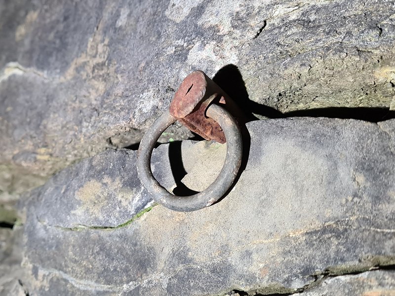
A metal wedge-shaped anchor that is hammered into a crack in the rock, and remains in place using only friction. They can be used to clip a carabiner to, or to tie a rope to directly, depending on the design. These belong to the climbing world, and should not be used for SRT. However, they are used for traditional aid climbing.
Though not used any more, pitons have the honour of being the oldest anchor used for caving. The original pitons were simply wedges of wood that were hammered into a crack. These had been used by miners for centuries as a way to attach tools or pipes to a wall, and they will have used them while exploring caves, but it is not known if these were ever used for load bearing purposes. Mountaineers used wooden wedges for load bearing purposes at some point around 1850. In 1875, American climber George G. Anderson used eyebolts held in by wooden wedges which he manually drilled into the rock, during his climb of Half Dome in Yosemite National Park. The eyebolts could have been used as pitons, since they were a nail with an eyelet, but he chose to drill holes instead. Metal pitons started out as basic nails used in Alpine mountaineering, used only in the event that there were no suitable naturals to attach a rope to, exclusively for descending. The first known record of their use for a load bearing anchor as an attachment for a rope is by French mountaineer Jean-Estéril Charlet-Straton, during an 1879 ascent of Petit Dru in the French Alps, though it is highly likely that others had already used them for that purpose, without documenting it. A "pin" piton with an eyelet was used by Otto Ewald Ufer on Talwächter in Germany, in 1881. At that time, they were known as "iron stanchions" in Britain, and "des coins ou pointes d'acier" (iron wedges or spikes) in French. The vast majority were drilled into solid rock rather than being hammered into an existing fracture. In 1890, they described by Austrian mountaineer Robert H. Schmitt, as being hammered into a natural crack in the rock, to descend from a mountain in the Tyrol region of Austria. They were referred to as "Mauerhaken" meaning " wall hook", a name which continued to be used in German, but there was no description of their design, apart from being made of wrought iron. They were treated as standard climbing equipment, not something new.
By 1893, they were shown by British mountaineer Claude Wilson as being made from a round nail with an eyelet at one end, where he also first used the term "piton". They were very clearly described as being hammered into an existing natural fracture. Pitons were then most heavily used in the Tyrolean Alps of Austria and Italy, and The Dolomites of Italy, where they would typically be hammered into existing natural fractures, with the start of the 1900s seeing a surge in their usage. By 1905, pitons with integrated lose rings for threading the rope through, appeared in Germany and Austria, but they were generally despised by older mountaineers in Southern Germany. In 1908, pitons were sold commercially, possibly for the first time, by Sporthaus Mizzi Langer in Vienna, Austria, though the design was not shown. Paul Preuss, who was one of the harshest critics of aid climbing and the use of any artificial climbing aids, died in 1913, after a fall that was caused by him not having adequate protection. Along with other notable accidents, this proved to be a turning point in the acceptance of pitons. Pitons were called "le clou" (nails) in French by 1916, and "piton de fer" (iron spike) by 1918, at which point their use in the mountains for climbing was despised by many French mountaineers. Just 10 years later, French mountaineers were embracing them.
The first flat pitons with an integrated eyelet that was forged in a single piece were designed by Austrian mountaineer Hans Fiechtl in 1920, and made by a blacksmith in Münster, Germany. This design was recommended in a 1920 German and Austrian climbing newsletter article by Hermann Amanshauser (later a Nazi SS officer), as a way to connect a rope (via a carabiner) as part of a safety upgrade for climbing, inspired by yet another climbing accident caused by inadequate protection. The new design became known in German as the "Fiechtlhaken", meaning "Fiechtl hook", and could be purchased in a design for vertical cracks, and a design for horizontal cracks. They appeared with that name, and the older type with an integrated ring was referred to in 1921 as a "Ringhaken", meaning "ring hook", in Franz Nieberl's book Das Klettern im Fels. Mizzi Langer's pitons, referred to as the "Mizzi Langerhaken", were shown as having a long, flat blade pointing into a vertical crack in the rock, then a 90° bend producing a flat face hanging down parallel to the rock, a rather odd design most closely resembling an angled tent peg, with the two sides squashed together. The hole passed through that flat face, pointing towards the rock, and will have caused the load to be placed some distance away from the rock, creating a lot of leverage. In 1922, ring pitons and Fiechtl pitons were described as being 12-15 cm long, in Anwendung Des Seiles, published by the Bavarian section of the German Alpine Club. In 1924, German mountaineers Willo Welzenbach and Fritz Riegle used pitons hammered into ice to secure a rope while climbing Weisbachhorn in Austria, removing them afterwards by chipping away the ice. In 1925, the summer catalogue from Sporthaus Schuster in München, Germany, listed a serrated piton specifically designed for use with ice, branded with their own ASMü brand. They called it an "Eishaken", meaning "ice hook", and it could be considered an ancestor of the ice screw, but it was far more prone to causing the ice to break. (The name had previously been used by some authors to refer to ice axes in the previous century, but those had normally been called "Eispickel" meaning "ice pick" since around 1875.) In 1926, Anwendung Des Seiles described ice pitons as being 20-25 cm long.
Pitons were probably first used in caves in the Grenoble region of France. Pierre Chevalier describes in Subterranean Climbers (1951), how members of the French mountaineering/caving club Les Jarrets d'Acier, including Henri More, were using a "ring bolt" or a "ring welded into the shaft edge" as anchors somewhere between 1924 and 1932. According to the same book, these were pitons with a ring attachment, which were inserted into a hole created using a star drill. They were used for canyoning in the same area in 1933. French caver Guy Labour used pitons in the Dent de Crolles system in 1937, and subsequent exploration in that system by many cavers then used pitons extensively. In 1948, hollow ice pitons were developed in Germany, but they did not have a screw thread. Pitons were the cause of a caving accident in 1941 where a piton came out and caused Fernand Petzl to fall down a pitch during the exploration of the Dent de Crolles. British mountaineers continued to discourage their use for mountaineering in the 1940s, as they encouraged poor climbing style, relying on equipment. In 1944, French caver Henry P. Guérin stated that pitons might be made from steel or duraluminium. In 1947, American climber John Salathé made the first hard steel pitons, which could be hammered into harder rock, last a lot longer, and were more likely to have enough grip to be trusted.
British cavers were using pitons by the late 1940s for traverse lines. Swiss mountaineer Erich Friedli developed the first threaded ice screw in 1960. Austrian mountaineer Sebastian "Wastl" Mariner designed the first commercial version for Stubai/Marwa in 1961, which was more like a P-hanger with a corkscrew on the end. By around 1962, twisted ice pitons were being made by Steidle (presumably in West Germany), which were simply a lightly twisted rod, which would have provided a little extra grip, but were too minimal to work as an ice screw. These are sometimes mistakenly shown as being a precursor to ice screws. In 1963, British caver T. Charles Bryant wrote in the Wessex Cave Club journal about a type of piton that had a screw thread on a tapered shaft, very much like an eyelet screw, which could be screwed into a drilled hole. These were called ring expansion screws, and were used by rock climbers for aid climbing. During the 1960s, a hybrid ice piton that was hammered in, but had a screw thread that allowed it to be screwed back out, was developed in the Soviet Union. Several designs were then produced in other countries, some of which could also be used in frozen soil. German mountaineer Hermann Huber working at Salewa developed the first hollow ice screw in 1964, and although it was missing the convenient handle which features on many modern ice screws, this is the first ice screw that actually looks and functions like a modern ice screw, with cutting teeth and an external screw thread, on a hollow tube. The use of pitons with caving continued until spits were developed in the early 1970s. Even during the 1970s, the first SRT instruction manuals to include Alpine rigging still showed how to use pitons. During the 1970s, American climber Greg Lowe developed a hollow version of the ice pitons that could be hammered in and screwed back out, called a Snarg.
This history section only covers pitons. This article also has a detailed history of many of the other devices and techniques that are used for vertical caving.
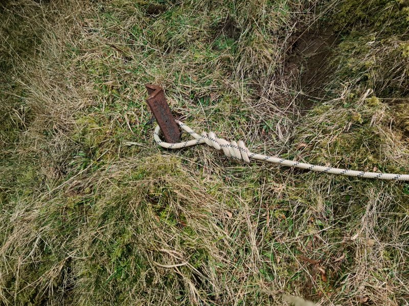
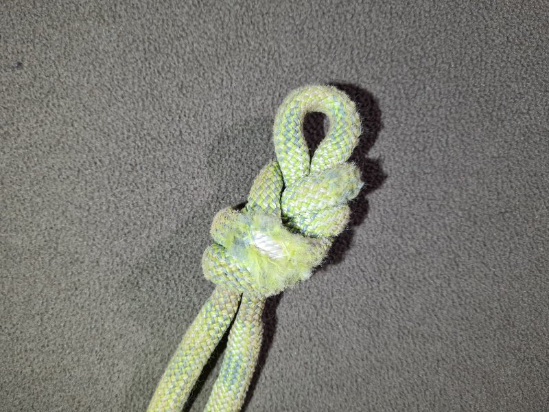
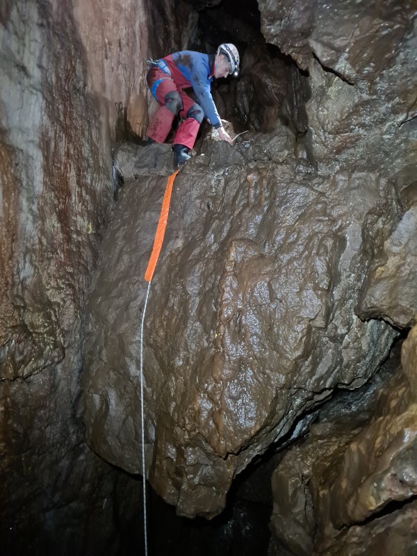
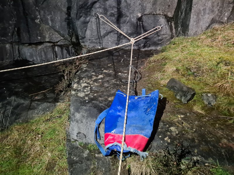

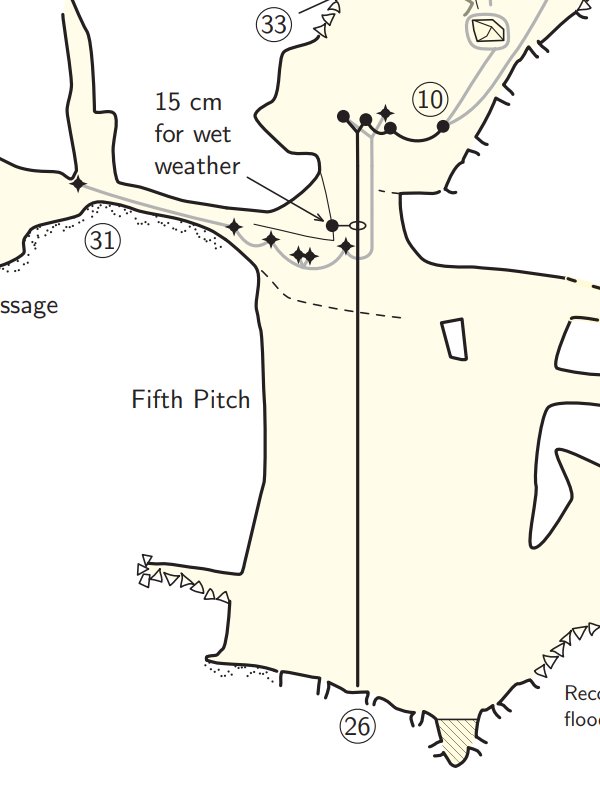
Thin rope/cord which is passed through the anchors or carabiners which are set up for a pull-through at the pitch head. The rope/cord is looped all the way down to the base of the pitch, where it usually passes through another pair of anchors to prevent it from tangling. This is used to pull a rope up to the pitch head from the pitch base, to allow access to an aven without having to leave a fixed rope in place. One common approach is to attach the rope to the anchors at the pitch base, and treating the top anchors like a pulley while using the other end of the rope for prusiking and abseiling (with the associated risk of abseiling on the wrong side). This method causes a lot of wear to the anchors at the top, due to the movement of the rope, but is typically used when there is only a single anchor at the top with a very large ring. Alternatively, the end of the down rope can be whipped or tied to the pull-up cord, using a knot small enough to pass through the anchors or carabiners at the pitch head. The end of the rope may be prepared for this purpose by stitching a short length of thin cord to the end, so that it can be tied with a smaller knot. The rope is set up as a standard pull-through with the carabiner clipped around the pull-up cord returning from the pitch head. As the tail of the rope descends, it will feed through the carabiner, leaving the rope rigged as a standard pull-through. Alternatively, the rope can be set up with a large knot tied half way down it, and the pull-up cord can be pulled until the tail reaches the pitch base, and the knot reaches the anchors at the top. The knot then supports the load simply by being unable to pass through the anchor. For this method to work, you must know the size of the anchors at the top, so that the knot can be made suitably large. Alternatively the knot (for either of the previous two approaches) can be tied at the end of the rope instead of the middle, and the knot can also be tied to the pull-up cord when it reaches it. This allows the shortest of all rope configurations to be used, where the rope is as long as the pitch instead of double.
The idea behind pull-up cords had existed for centuries. Maghrebi traveller Abu Abdullah Muhammad ibn Battutah visited Alexandria, Egypt, in 1326. He recounted the story of how a (presumably Mamluk) archer had previously used a bow an arrow to drag a pull-up cord over Pompey's Pillar, and used it to pull up a rope which he could then use to climb the pillar. It is not known when this actually took place, but it will have been some time before that year. When grappling hooks were to be thrown up to high platform (such as the walls of a castle), a thin cord could be looped through a hole in the grappling hook, which would be light enough to allow the grappling hook to be thrown. A rope would be attached to one end of the cord. When the grappling hook had hooked onto something, the other end of the thin cord could be pulled, which pulled the rope up through the hole in the grappling hook, so the rope could be used as a rope climb or for prusiking. This approach was described in 1719 by French author Gaspard II Grollier de Servière, as something that had been discussed by French inventor Nicolas Grollier de Servière at some point either during his military career or his retirement, between 1610 and 1689. French artist Francois Sebastien Fauvel used a kite to install a pull-up cord on Pompey's Pillar in Egypt in 1789, which was used to pull up a ladder, for the purpose of adding graffiti. This was repeated in 1798 by sailors, but instead of using a ladder, they pulled up a rope for hauling, which was used to raise a sailor, French architects Charles Norry, André Dutertre, Jean Constantin Protain and Jean-Baptiste Lepère, and several members of the Commission of Arts. Pulling up ropes with thin cords has been used in many other contexts too.
The first use of pull-up cords for caving is not known, but it would originally have been for ladders, so that a ladder could be taken through the cave, and hauled back up to the pitch head using ropes, so that only a single ladder was needed. The first version of this was used by French caver Édouard-Alfred Martel in 1892 in Aven de Vigne Close, and is described in the British publication Encyclopaedia of Sport, 1898, where if a ladder was not long enough to reach the bottom of a pitch, cavers could descend to a ledge, stop on the ledge, and then someone at the pitch head could lower the ladder further down on a rope so that the ladder could be rigged from there instead, allowing the team to descend further. With this approach, a caver would be left at each ledge, to reattach the ladder when it was pulled up. Pierre Chevalier, Hélène Guillemin and François Guillemin started using pull-up cords for ladders just like a normal pull-up cord pulled through a carabiner or metal ring at the top of the pitch, in the Dent de Crolles system near Grenoble in France in 1935, without needing a person at the top. This approach was used for many years afterwards. French caver Henry P. Guérin described a maypole in 1944 which had a pull-up cord that could be used to pull up a ladder, without needing a person at the top, by attaching the rope at the bottom, just like a normal pull-up cord. Pull-up cords were used with a pulley at the top starting from 1946 by French cavers Pierre Chevalier and others in the Dent de Crolles system. Pull-up cords for ropes were first used by French caver Daniel Martinez in 1972.
This history section only covers pull-up cords. This article also has a detailed history of many of the other devices and techniques that are used for vertical caving.
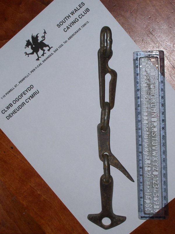
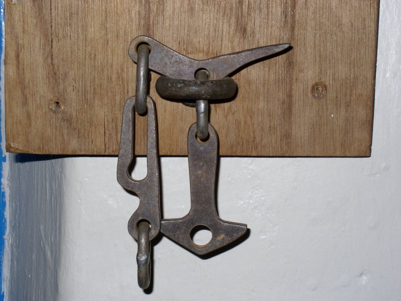
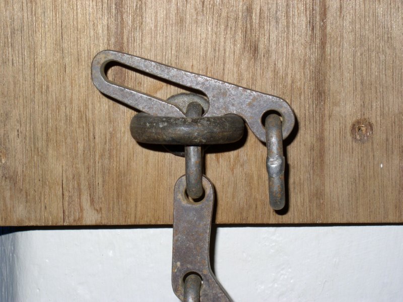
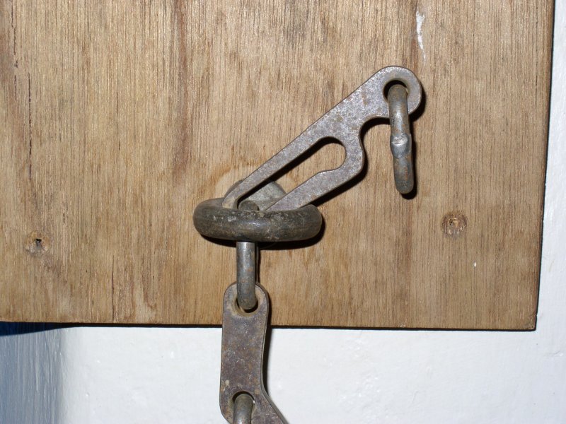
A special pull-up cord setup, using a vertically oriented eyelet anchor, with a second eyelet positioned above it. The pull-up cord passes through both eyelets, with the upper eyelet serving to pull the cord upwards from above the lower eyelet. The rope and cord are connected to opposite ends of the skyhook, which is a metal attachment that will pass through the first eyelet only when the cord is pulled upwards, and will lock into place on top of the eyelet. This allows the rope to be pulled up the pitch and locked into place. Before descending, the locking part of the skyhook is manually passed back through the eyelet, and a different piece is manually rotated sideways across the eyelet. Afterwards, the cord is pulled again, releasing the skyhook completely, and the rope can then be lowered down the pitch. Popularised by its use in the British Ogof Ffynnon Ddu system, on The Skyhook pitch. This should not be confused with a Petzl Sky Hook, which is a brand of progression hook.
The original skyhook was created by British caver Peter Harvey in 1953, originally intended to be used to pull a ladder up pitches that had been accessed using a maypole, a purpose which it was commonly used for in a few caves, particularly Ogof Ffynnon Ddu and Dan yr Ogof. It was most famously used on The Skyhook pitch, which was discovered in 1968 from above, and remained configured for access that way for several decades. A second one was placed in the entrance porch of the South Wales Caving Club, so that visitors could see how it worked, and practice before putting it into use underground. Some other clubs copied the designs so that they could use their own one, and not have to borrow the one belonging to the South Wales Caving Club.
This history section only covers the skyhook. This article also has a detailed history of many of the other devices and techniques that are used for vertical caving.

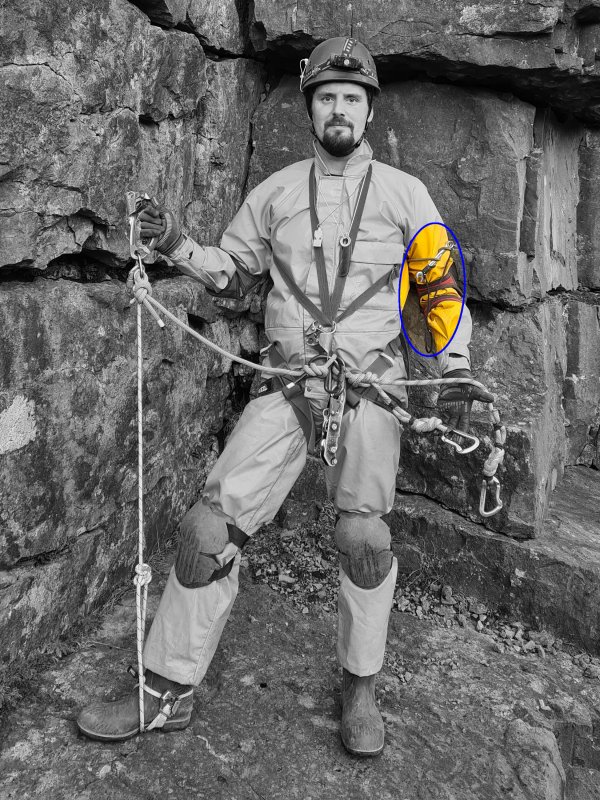
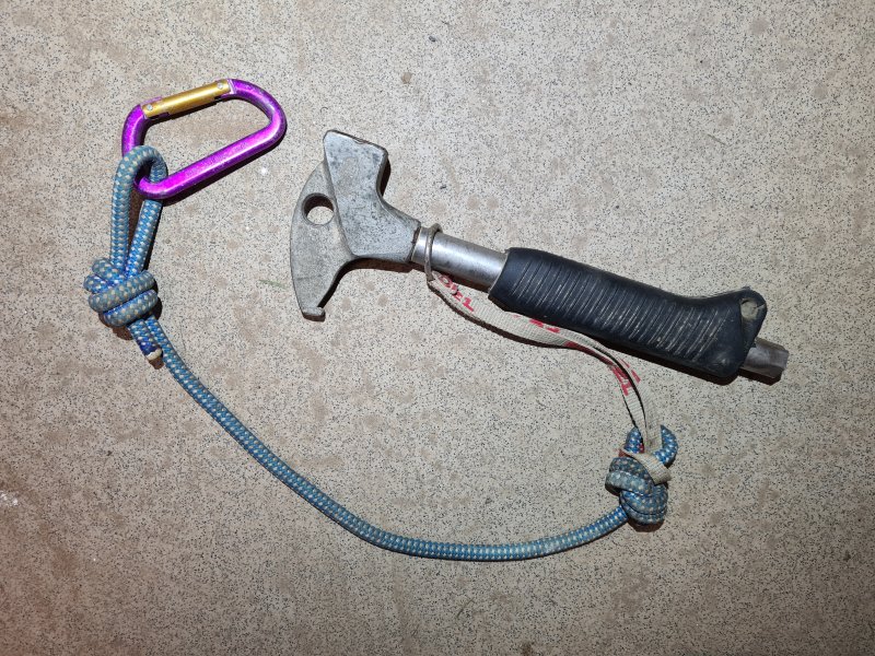
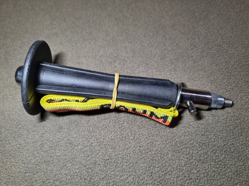
An electric tool to make holes, used when bolting up an aven or initially setting up the anchors on a pitch, which can then be used for all future rigging. Drills are cordless, powered by batteries. Drill bits are of the masonry type (designed for cutting into stone), and generally should be very high quality, with 4 or more "flutes" (spiral ridges). Drills must be connected to a gear loop via a tether, to avoid dropping them.
There are also various kinds of hand powered rotary drills and rotating hammer drills, typically with a crank wheel on the side which is turned, but these are very rarely used. However, some mining drills have been used, which push against one wall while drilling into the other (much like a stemple), with a rotating collar which is manually turned to turn the drill bit. As it rotates, the drill bit is retracted then hammered into the rock using a spring.
Pneumatic drills were invented in 1871 by Samuel Ingersoll, and were used in the mining industry. Australians Arthur James Arnot and William Blanch Brain invented the electric drill in 1889. Black & Decker released the first battery powered drill in 1961, but early ones were not suitable for caving related tasks. Electric drills were first used in caves with external generators. The earliest known record of this is that a Kango hammer electric powered chisel (rather than a rotary drill) was used with an external petrol generator to drill rock breaking shot holes in 1963 at the Waun Fignen Felen dig by the British South Wales Caving Club. The club used the same approach to drill half inch (12.7 mm) holes for through bolts while on expedition to Jama Balinka in Yugoslavia (now Croatia), in 1964 and 1966. The same approach was used in 1968 by the British Wessex Cave Club to drill shot holes at the Twin Titled niceties Swallet dig in 1968, and with a rotary drill by the Illawarra Speleological Society in the BD-2 dig in Bendethera, Australia for drilling shot holes. The same approach was then used with a rotary drill in the 1970s in the Grenoble region of France for installing anchors. (A generator and electric hammer were used to break rock rather than drill holes at The Great Cow Bone Cave at Finley Ridge in the USA in 1972, but it was a lot later before anchors were used there.) A hand-powered mechanical mining drill was described as being in use during the British caving expedition to Ghar Parau in Iran in 1972. In the late 1980s, battery powered drills finally gained enough power and capacity to be worth the effort of taking them a long distance into caves, and they started to take over from star drills. For big projects, the drill might be modified to use a fly lead, allowing an external battery pack to be connected, such as a lead acid or NiCad battery, with the associated weight that brought. At that time, some cavers were using pneumatic drills, with external generators on the surface powering air compressors, with lengthy high pressure hose pipes taking the compressed air far into the cave. During the 1990s, near-surface cave digs still sometimes used powerful drills powered by generators. By the early 1990s, 24 volt drills were being used, and powering those would typically require two small format motorbike lead acid batteries to be carried in and out of the cave, often crammed into an amunition box. This approach was used in many parts of Britain, and is what was used for scaling Titan, Peak Cavern in 1999. Makita released the first lithium ion drill in 2005, and cavers started using lithium ion drills shortly afterwards.
This history section only covers drills. This article also has a detailed history of many of the other devices and techniques that are used for vertical caving.
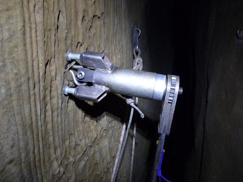
A device for removing anchors that have become damaged or obsolete, ideally without damaging the rock that they were placed into. The exact approach will depend on the type of anchor and how it has been placed. It is common to drill the hole for a through bolt deeper than it needs to be when installing it, so that when it is no longer needed, it can be loosened, and hit in further with a hammer to bury it below the surface. The exposed part of an anchor may be cut off with an angle grinder. A hollow drill bit may be used to encircle the anchor, drilling a slightly wider hole into the rock, with the anchor nestled in its centre, removing it like an apple core. A drill may be used to remove rock next to the anchor, then the anchor may be hit sideways into the new hole to free it. A bolt may be screwed very hard into a spit, pushing against its wedge to force the spit nut to move outwards, out of the rock. A hardened metal cutting drill bit may be used to drill away the metal of a spit. In all of these cases, resin may then be used to fill the hole, and hide it. However, if the hole is not reused, then it effectively compromises the surrounding rock, preventing a new anchor from being placed in a similar position, and causing bolt rash.
A dedicated extractor may rely on some types of anchor being prevented from gripping the rock, such as using heat to damage the resin of a P-hanger, or using a drill to rotate a through bolt so that its expansion sleeve cuts into the metal wedge, preventing it from expanding properly. The bolt extractor tool is then used to pull the anchor outwards with a lot of force, pushing against the rock surrounding the anchor so that the rock remains intact rather than being fractured. Typically, these work by tightening a nut on a screw threaded rod, with the rod pulling on the anchor, and the nut resting on a housing that pushes against the rock around the anchor. In particular, the IC anchor and discontinued DMM branded Eco anchor are P-hangers that are designed to be removable from the rock in this way, leaving a hole that can be reused for a new anchor, keeping it in the same position as the previous one. This is why they are approved by the Council for the Northern Caving Community. The success rate with through bolts is much lower, and they may still grip the rock, causing it to be destroyed as they are pulled.
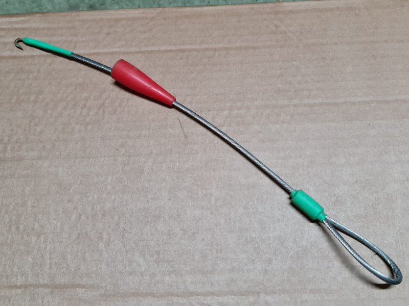
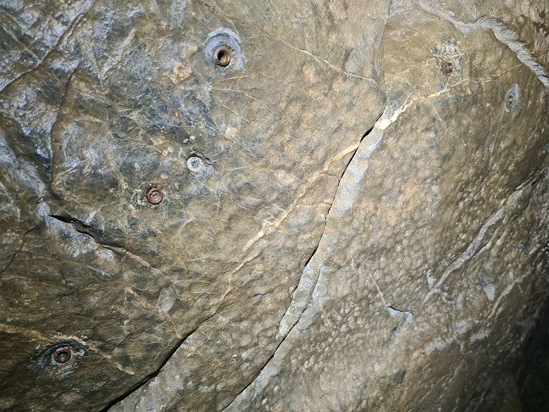
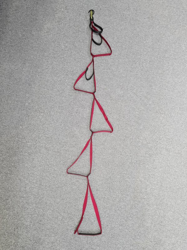
Vertical ice caves (caves in rock, with significant quantities of ice in them) and glacier caves (caves formed within ice) are explored in the same manner as normal rock caves, but may need additional techniques and equipment. Some normal rock caves, particularly those at high altitude, may have a cone of snow funnelling down into an entrance, which requires other approaches. In general, the additional techniques are borrowed from ice climbing, and therefore the equipment is too. Some of these, such as Abalakov threads have made their way into standard caving too, so they are included in those sections instead.
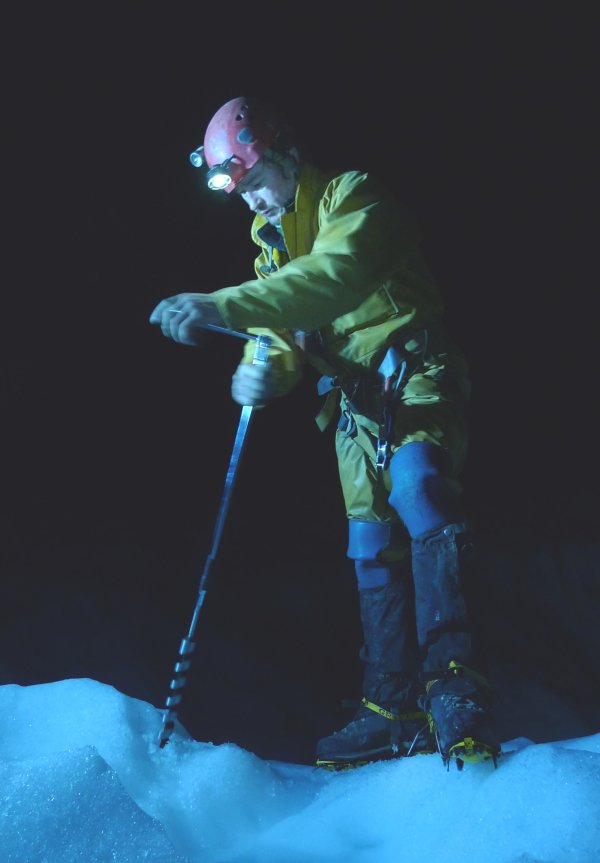
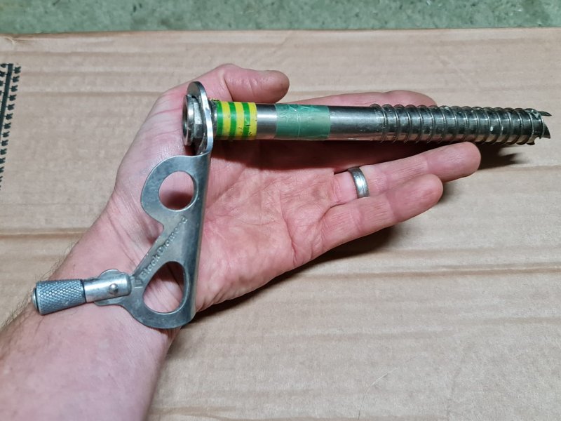
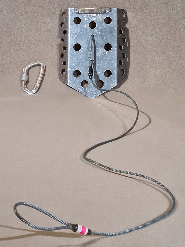
Rope access is the professional use of SRT and related techniques, for industrial purposes. Arboriculture, the managing of trees, uses rope access, but typically uses its own approaches. I do not pretend to be an expert in rope access or arboriculture, as I am not trained in either. However, some of their terms may be confused with similar terms used in vertical caving, or their approaches have been tried and largely abandoned with vertical caving. As a result, they are worth including here, to aid understanding. This section is intentionally not comprehensive, as it only covers the terms that might be helpful for a caver to know. Rope access and arboriculture have their own extensive vocabularies that are different in different regions, and often used in formal regulations. For the most part, they are not in the scope of this document.
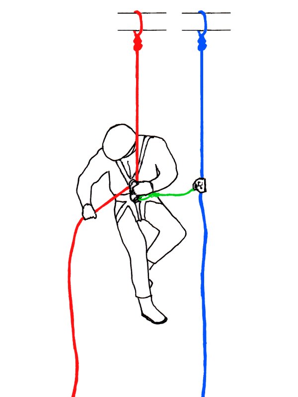
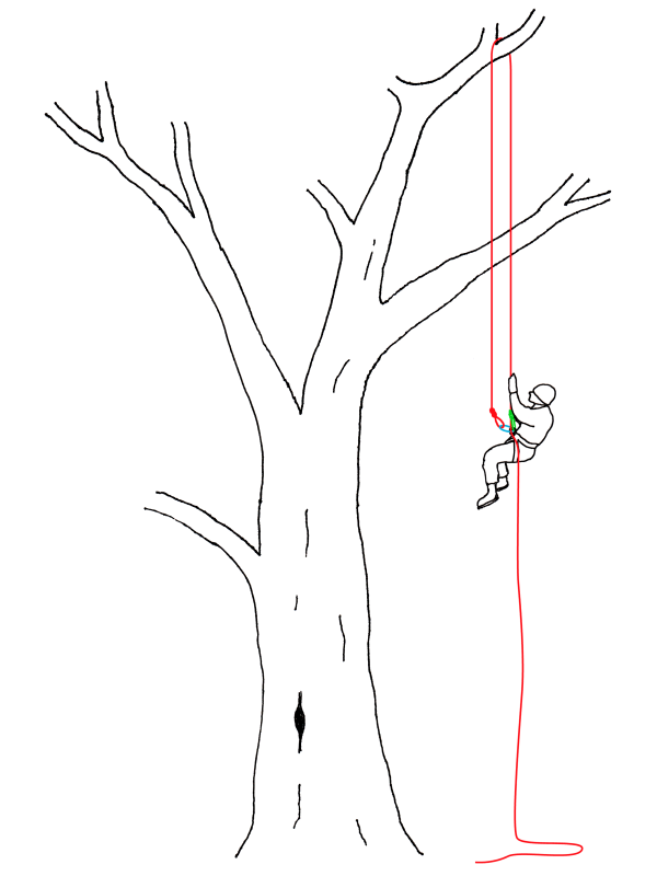
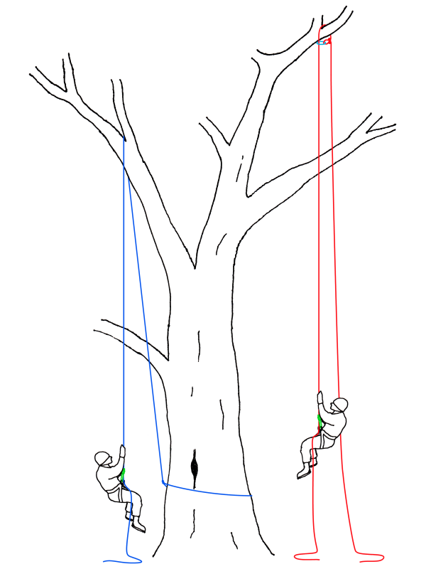
Knots are the fundamental building blocks of rigging. Several knots are used, depending on the specific task the knot is being used for. Many knots are designed to be loaded in specific directions, depending on what directions the forces will act on them when they are in use. As a general rule, the knots used are intentionally quick to tie, requiring very little muscle strength. They are also generally very easy to untie when needed, so that the rope can be reused for another purpose (though there are some intentional exceptions). They are stable, and should not untie or capsize accidentally. They do not reduce the strength of the rope too much. They also use minimal amounts of rope. They need to be quickly recognisable, so that they can be double checked by other users of the rope. Knots should only be used if they have been rigorously tested to prove that they serve all of these requirements, and can safely cope with unexpected loading.
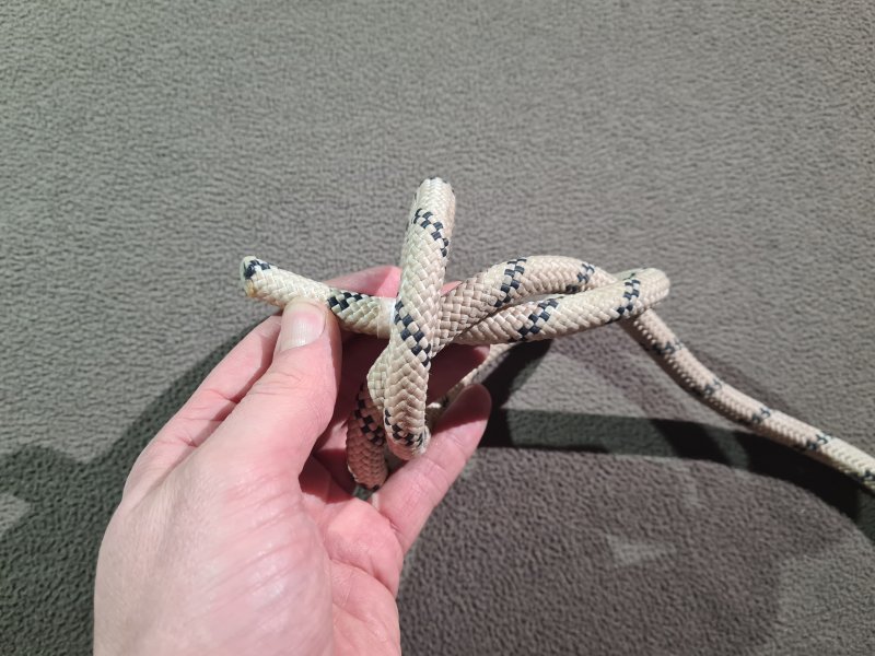
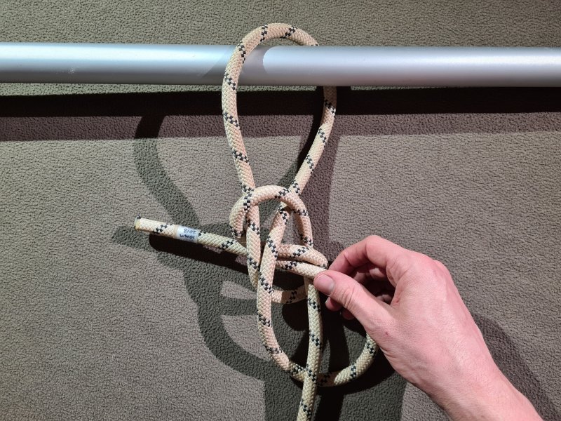
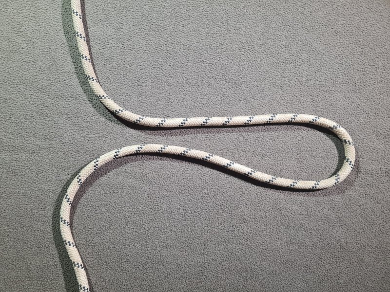
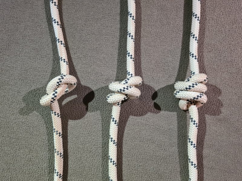
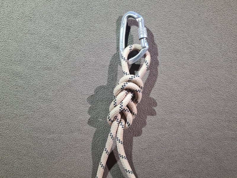
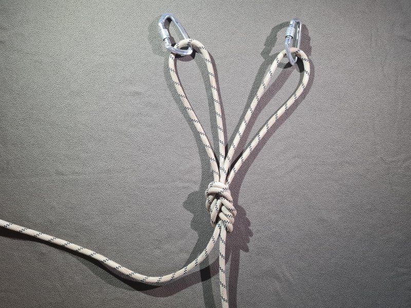
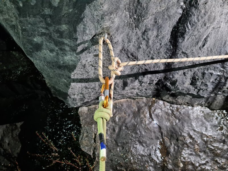
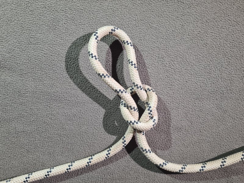
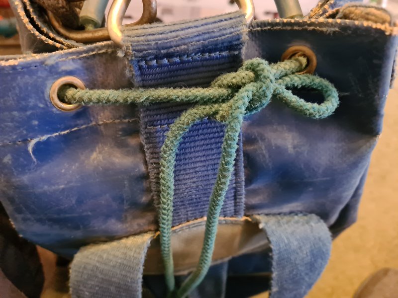
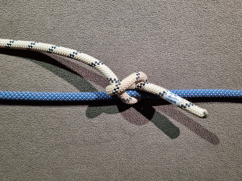
A knot where the rope wraps around something else, gripping it tightly in order to hold on to it. With vertical caving, most hitches are tied around another rope, or another part of the same rope.
You may see an inaccurate statement written in various places that "a hitch needs an object or another rope to tie it", and "without the object or other rope, it will fall apart". This is not correct at all, no matter which version of English is being used, as several hitches hold their shape when they are not tied around something, such as the half hitch, which is simply an overhand knot tied around something, and the timber hitch, which is a figure of 9 or a different dressing of the Capuchin knot tied around something. The timber hitch, and many of its variations (such as ones based on the figure of 8), even keep their dressing when not tied around something. At the same time, you might see a claim that hitches are not knots because a knot "is self-contained and selfsupporting", and "does not need another object or rope to maintain the integrity of the knot". This relegates a sheepshank into the no-man's land in between, since it is not tied around something, but can fall apart if the object providing tension to the rope is removed (or you just breathe on it too much - it's a very unstable knot, which is why it is not used at all for vertical caving).
The reason for this mistaken understanding is that some American sailors from 1944 might have said that hitches are not knots. They are. We are cavers, and even if we were sailors instead, this page specifically uses British terminology. According to the Collins (British) English dictionary, a knot is "any of various fastenings formed by looping and tying a piece of rope, cord, etc., in upon itself, to another piece of rope, or to another object", and that very explicitly includes bends and hitches. The claim that they are not knots comes from the American made Ashley Book Of Knots, by sailor Clifford Warren Ashley, 1944, page 12; "At sea, the whole subject of knots is commonly divided into four classifications; hitches, bends, knots and splices. [...] The term knot itself is applied particularly to knobs and loops, and to anything not included in the other three classes, such as fancy and trick knots". However, that same text also states that the word knot "in its broadest sense [...] applies to all complications in cordage, except accidental ones such as snarls and kinks, and complications adapted for storage, such as coils, hanks, skeins, balls, etc.". Now even ignoring the fact that most British people would happily call an accidental hair tangle that cannot be undone a knot, this sentence clearly calls a hitch a knot. The Ashley Book Of Knots also states in the same text that the word could instead exclude almost all knots, leaving only the ones used to stop a rope fraying, or to provide a handhold (so the overhand on a bight is not a knot unless you tie it in a knotted handline - what nonsense!).
The same words used in different countries, different contexts and different years can have different meanings. The Oxford English Dictionary states that a knot is in fact "an intertwining of a rope, string, [...] hair, etc., with another, itself, or something else to join or fasten together", clearly including bends and hitches, and goes on to explicitly include "a tangle in hair, knitting, etc.", without requiring them to be intentional. In commonly understood English in Britain, a hair tangle, a hitch, a coil, a bend and a loop knot would all be considered knots, and a sheepshank is a knot, even if it can't hold itself together once the tension is released. We are not all sailors, we are not all Americans, and this is not 1944.
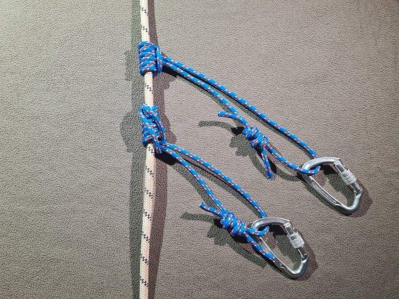
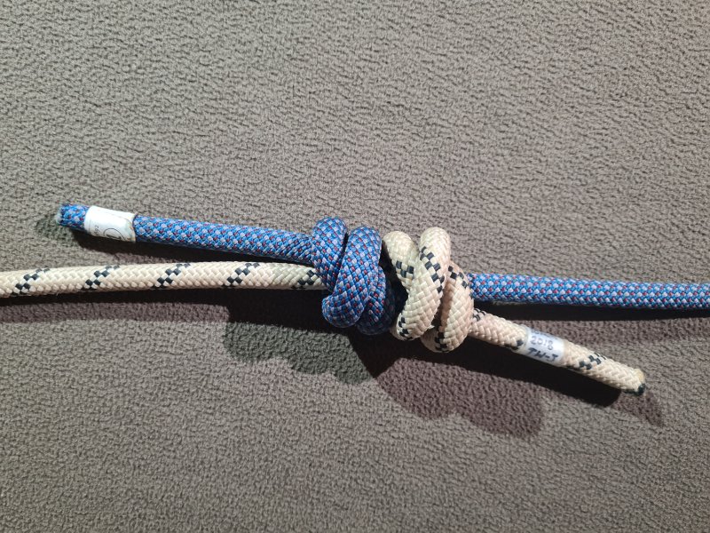
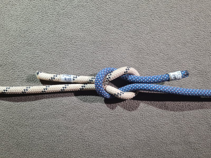
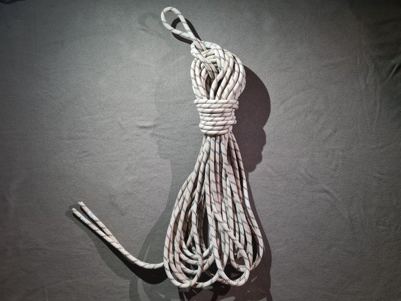
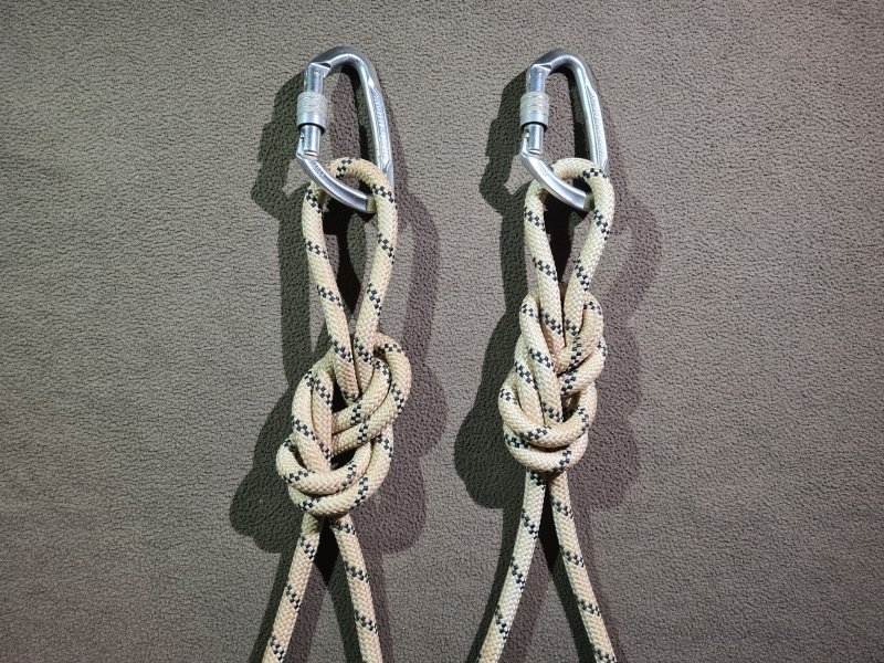
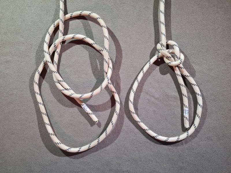
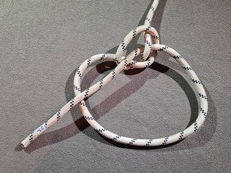
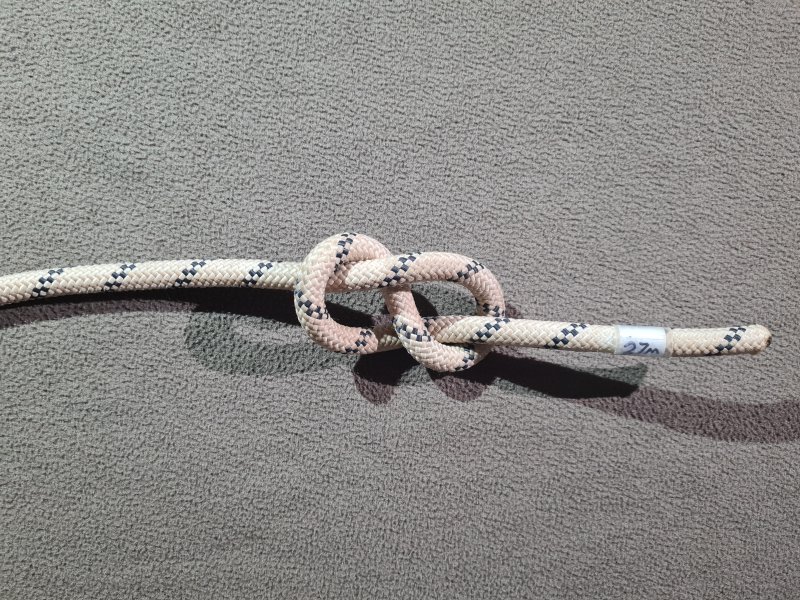
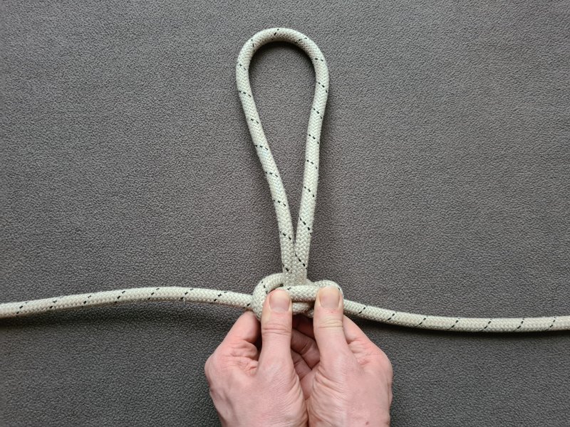
This list of knots is intentionally not exhaustive. It covers the knots that are most likely to be used, whether intentionally or by mistake, or the knots that are used to construct a more common knot. It also covers a few of the commonly taught knots which should never be used, since a number of organisations teach knots which have serious shortcomings, and should never be allowed in safety-critical situations.
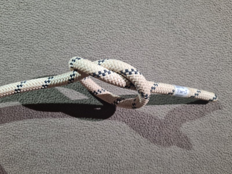
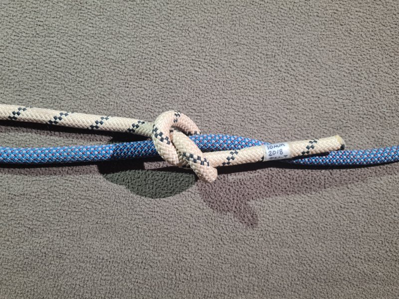
Avoid
A hitch tied by threading, that is sometimes used by mistake instead of a stopper knot. A doubled form of the half hitch tied on a bight may be used to lock off some types of descender, particularly as a form of hard lock for some designs of rack. Made from an overhand knot that is tied around another rope, or another piece of the same rope. It is supposed to be dressed as a noose version of a single hitch, but that is quite unstable unless it is kept under constant tension, so the knot tends to end up dressed like a half knot. Sometimes used to loosely tie the end of a rope to a tackle bag so that the ends can be easily found, or so that the bag can be hauled up on the end of a rope.
Avoid
The most simple of all stable noose knots, which can be tied on a bight or by the most basic rethreading of an overhand knot. This knot is never used on its own, as there are many better nooses which are less prone to slipping (such as the poacher's knot). However, this knot forms an integral part of the butterfly knot, and is one of the steps used to tie a butterfly knot by rethreading. It can also be used as a very quick method to tie a bowline, putting the tail through the noose, then pulling the noose until it capsizes into a bowline; which variation of bowline gets created depends on which tail is used, and which direction it passes through the noose. To be properly called a slip knot, the knot should be a slipped version of the knot, which means it is not useful at all for SRT.
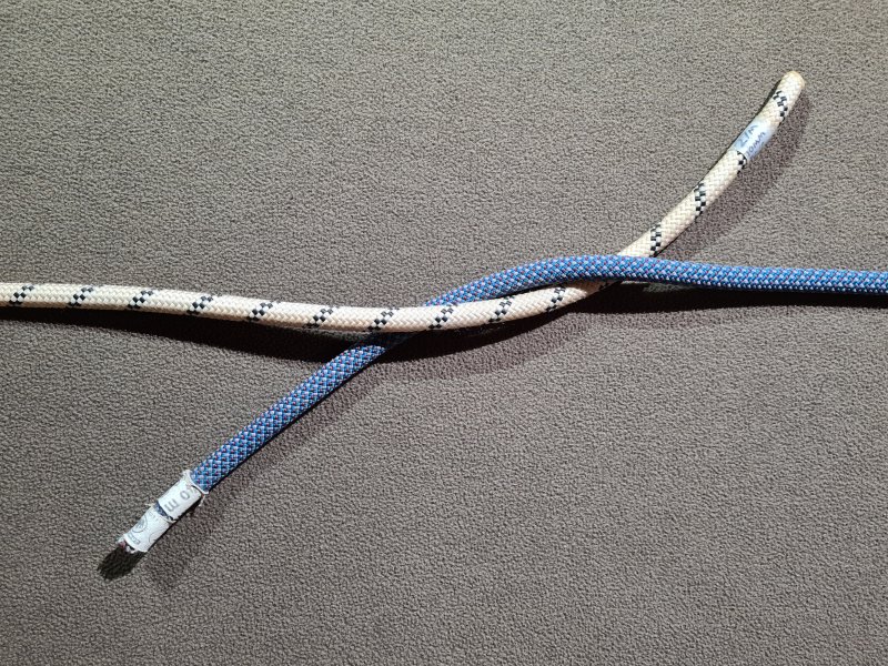
Avoid
A binding knot tied by threading, that is very rarely used on its own when tied from two separate ropes, but may be used as part of a reef knot. Sometimes used on its own when tied with a single piece of rope, either used by mistake instead of a stopper knot, or as a half hitch that is not dressed the way it is supposed to be. Made from an overhand knot that is tied with two ropes, or two ends of the same rope.
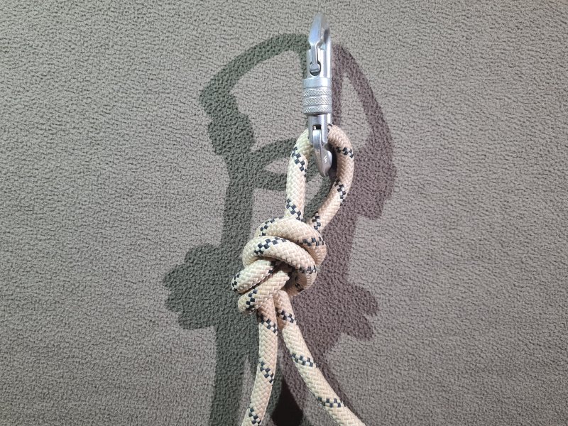
Common Use with caution
A knot tied on a bight, used to create a loop that can be clipped into a carabiner. Sometimes used to attach cows tails to a D-ring. Very hard to undo, and should not be used in rigging. Resistant to cross loading at the level that it might receive from a caver clipping their cows tail into the loop and pulling against an anchor, but severe cross loading, in the region of 960 kg (480 kg across the knot itself), causes the knot to deform and start rolling continually down the rope until it falls off a tail and unties. Made from an overhand knot tied using a bight.
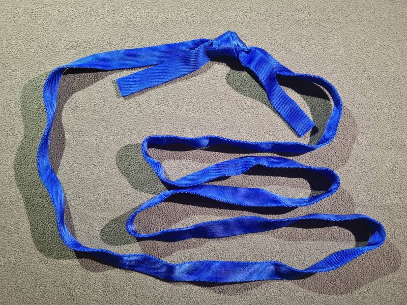
Common Recommended
A bend knot used to turn a length of tape into a sling. Almost impossible to undo once fully set. Made from an overhand knot on a bight, which is rethreaded from the wrong end, so its loop connects to both ends of the knot.
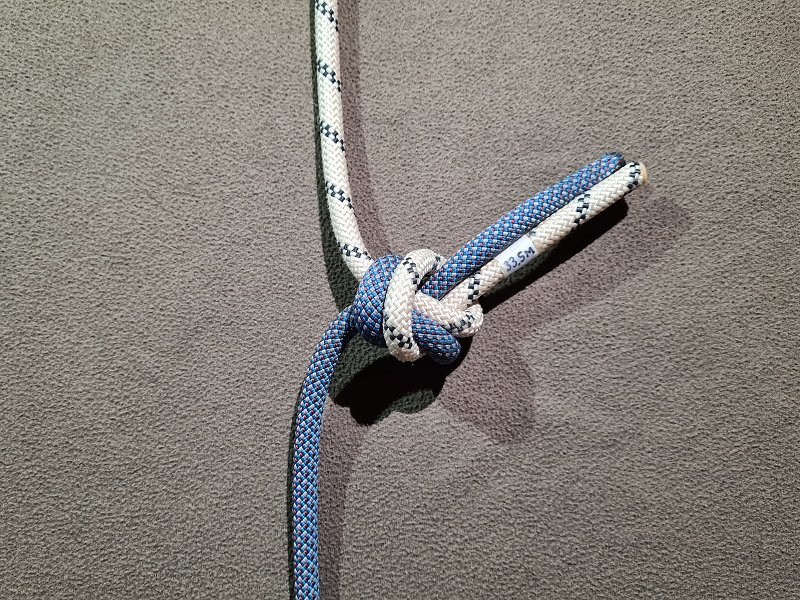
Avoid
A bend knot used as a way to join two ropes to make a longer rope, but with limited applications. It reduces the strength of the rope by around 78%, but not because of any weakness in the knot, which is very strong when used as a tape knot. Its weakness lies in the fact that it is essentially a cross loaded version of the overhand on a bight, and when loaded to levels in the region of 480 kg, the knot will deform (it capsizes into the same knot) and start rolling continually down the tails of the ropes, until it falls off the ends and unties. These numbers are even lower if the knot has not been properly set, and are significantly lower on dynamic rope than on static rope. While this is more than it is likely to experience with normal SRT usage, it is far weaker than the normal safety margin that is expected by rigging knots, and really should be avoided. Sometimes seen as a rigging knot for a pull-through without a Y-hang, where it might be used to join separate ropes (one for loading, and one for derigging the pull-through), while simultaneously jamming against an anchor in order to support the load. There are much better knots for this purpose, such as a flat double overhand bend. When pulling the rope down the pitch, the knot can run over rough surfaces, and usually orients itself facing away from the surface, in a way that avoids snagging, which is why it is sometimes preferred over other bends, but the flat double overhand bend can do that too. Made from a tape knot with the second rope threaded from the same end as the first one.
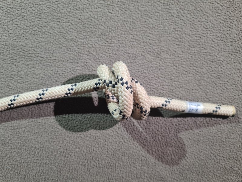
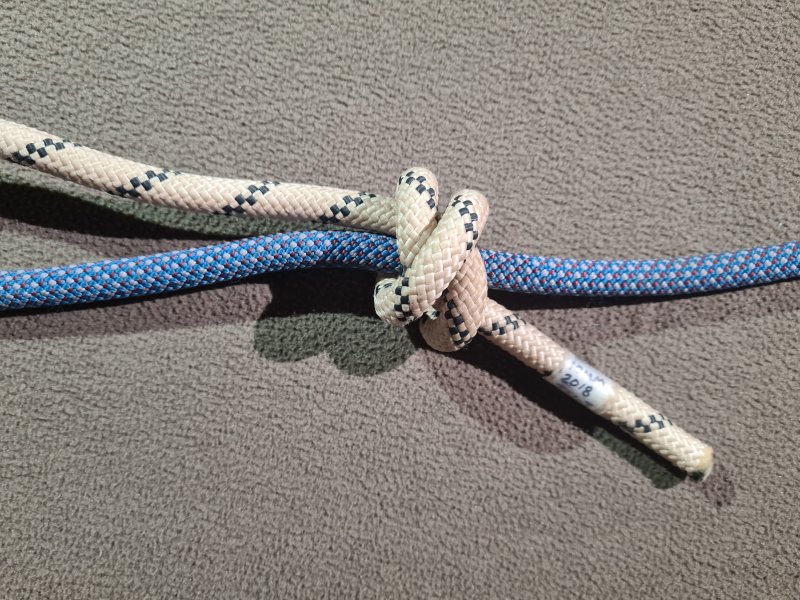
Common Recommended
A hitch tied by threading, that is used to prevent another knot from accidentally undoing. Made from a half hitch with an extra turn. Essentially a double overhand knot that is tied around another piece of the rope where it emerges from the other knot. The result is that the other knot can now be considered "stopped", such as a stopped bowline. Note that the term "stopper knot" refers to a class of knots that does not in fact include the knot that is called a stopper knot by cavers. Cavers use the term safety knot for what is called a "stopper knot" elsewhere. (The reason for this is that climbers often use the double overhand knot as their safety knot to prevent a rope from slipping all the way through a belay device, where they call it a stopper knot. In the caving world, the name stuck, but for the wrong reasons.)
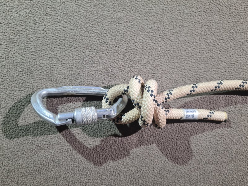
Common Recommended
A noose version of the stopper knot, tied by threading or on a bight, often used to attach carabiners to cows tails. Intentionally difficult to untie once set, because it is not supposed to be undone. Note that arborist websites, and some cavers, often mistakenly call it a "fisherman's knot" instead of a ¾ fisherman's knot. Sometimes mistakenly called a "barrel noose" but an actual barrel noose has one additional turn of rope. From personal experience, very few cavers seem to know the correct name for this knot.
Recommended
A bend knot tied by threading, used to turn a length of string or rope into a loop (such as a prusik loop). Sometimes used as a way to join two ropes to make a longer rope, since it can work with ropes of different thicknesses - a figure of 8 on a bight can be added to one of the tails to provide something to clip a cows tail into. It is considered to be the best way to join ropes to make a longer rope, and tests as the strongest of all common bend knots. Very hard to undo after loading (nearly impossible using hands alone), so when used to join ropes, it is usually coupled with another knot tied with the fisherman's knot in its loop such as an alpine butterfly knot, with the other knot taking the load, and the double fisherman's knot only serving as an emergency backup. Made from two stopper knots, pulling against each other.
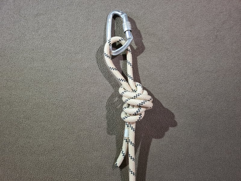
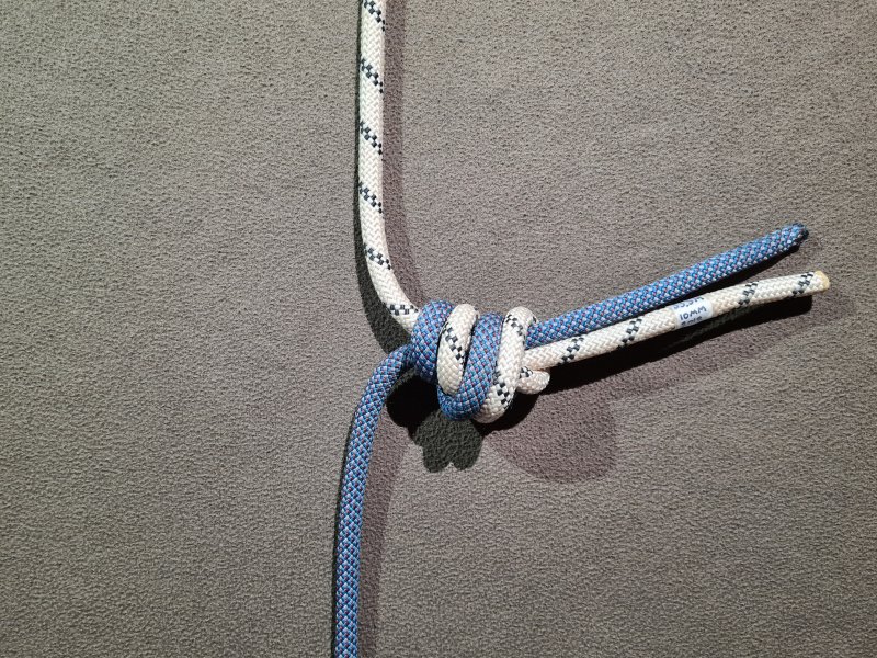
Recommended
A bend knot used as a way to join two ropes to make a longer rope, but with the ropes pulled in an unusual fashion. Sometimes used as a rigging knot for a pull-through without a Y-hang, where it might be used to join separate ropes (one for loading, and one for derigging the pull-through), while simultaneously jamming against an anchor in order to support the load. A far better knot than the flat overhand bend, which is also used for this purpose. When pulling the rope down the pitch, the knot can run over rough surfaces, and usually orients itself facing away from the surface, in a way that avoids snagging, which is why it is sometimes preferred over other bends. If the two ropes are of different diameters, then for maximum strength, the knot should be tied so that the thinner rope ends up making the turn closest to the neck of the knot, where the loaded ropes come out. This is shown in blue in the illustration. Made from a double overhand on a bight with the two tails replacing the usual loop.
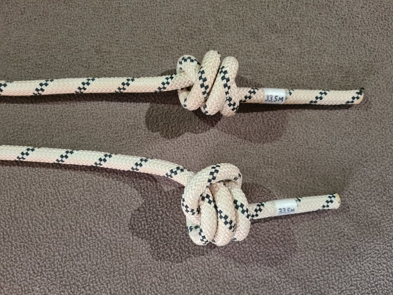
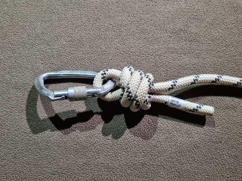
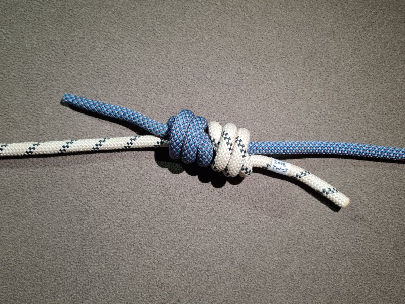
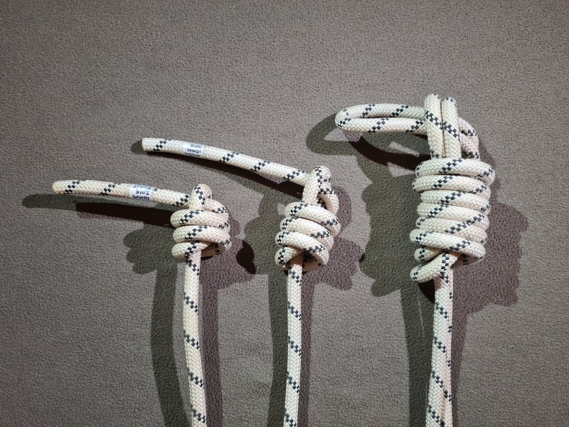
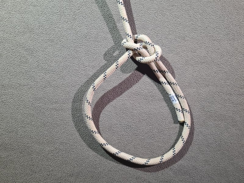
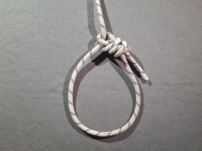
Common Use with caution
A loop knot that can only be tied by threading, and is well known for the mnemonic used to remember how to tie it; the rabbit comes out of the rabbit hole, runs around the back of the tree, then back down the rabbit hole. Alternatively, it can be rapidly tied by threading the tail through an overhand noose, and pulling the noose until it capsizes into a bowline, known as the "quick bowline". The ends of the loop emerge from different parts of the knot, so the loop remains open, which is useful for some purposes. Sometimes used at the start of a rope to connect to a backup. Has the benefit that it is relatively easy to tie, and easy to untie after loading. The ease of untying the knot is its major failing, and it is very prone to accidentally coming undone if pulled the wrong way, cross loaded, or repeatedly loaded and unloaded. Just a few pulls in the cross-loaded direction can be enough to completely undo the knot, and just a single pull on the tail can cause it to capsize so that it undoes completely! Must always be used with a stopper knot, turning it into a stopped bowline, to largely mitigate this very serious risk.
A bowline can also be tied in "multiple bowline" format to create a Y-hang and potentially a traverse line and backup as well. In this format, a normal bowline loop is tied part way along a rope, which is used to create one arm of a Y-hang, while the other arm of the Y-hang is created using a second bowline tied on the very long tail of the first bowline. This approach leaves the rigger without a safety line while working at the pitch head. Further bowlines can then be added for a traverse line and backup, and the final bowline must have a stopper knot. However, because the bowline is a threaded knot, it can only be practically tied near the end of a rope, and so multiple bowline format is generally only used when creating a Y-hang without a backup. The load on the second bowline pulls on the tail of the first bowline, which means the first bowline can suddenly capsize into an overhand noose if someone clips a cows tail into the piece of rope between the two bowlines. The first bowline can also capsize into an overhand noose when cross loaded, such as when a cows tail is clipped into the loop of the first bowline. This results in the Y-hang becoming unbalanced, and the load being placed only on one arm of the Y-hang when it is subsequently loaded. Once it has turned into a noose, only the second anchor is then used correctly for support, and if that anchor fails, the first anchor will only take over if the knot from the second anchor jams into the noose or the first anchor. This competely defeats the safety aspect of a Y-hang. If it has turned into a noose and the first anchor fails instead, the knot immediately slips, causing a significant shock load. It is unlikely to accidentally undo when the down rope is loaded, since the first bowline is being pulled in the normal load direction at the same time as its tail is being pulled by the second bowline. There are many better knots to use instead of a multiple bowline, such as a butterfly knot or Alpine butterfly knot, but the multiple bowline may be preferred when connecting the rope directly to an anchor instead of using a carabiner, since it can be more easily tied by threading through itself than the more common Y-hang knots.
A doubled variation of the bowline may sometimes be used part way along a rope by taking a very long bight of rope, and tying it as a doubled stopped bowline around a natural. However, this requires an excessive amount of rope, and if tied without a stopper knot, it leaves an incredibly dangerous loop that someone might mistakenly think they can clip a cows tail into, but since it is actually the tail of the bowline, it can capsize the bowline if it is loaded. There are far better techniques, such as using a sling and carabiner. As a result, it is ony used in desperation when slings and carabiners are not available.
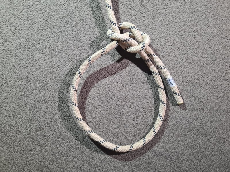
Use with caution
Variation of the bowline where the rabbit goes the other way around the tree. Needs a few more pulls to cause it to untie when cross loaded, but otherwise performs almost identically to the standard bowline, and should be treated the same way. It also needs a stopper knot.
Avoid
Variation of the bowline where the rabbit goes down the rabbit hole, around the root of the tree, and back up the rabbit hole. Used in some countries, particularly Russia. This is just as likely as a bowline to accidentally untie when cross loaded, and can also accidentally untie when used around a natural with high friction, such that the two sides of the loop receive unbalanced load. This knot should be avoided.
Avoid
Variation of the bowline where the tail is wrapped around one side of the loop, then passed back through the knot. More resistant to cross loading than a bowline, but relies on the knot being specifically set while it is being tied and used. If the tensioning is incorrect, or if repeated loading and unloading causes the knot to deform, it can capsize into a noose based on the figure of 8 knot. This knot is therefore significantly inferior to a stopped bowline, and should be avoided.
Good but unknown
Variation of the bowline where the tail is fed back through the knot, weaving behind and in front of the rope in the knot. Far more resistant to cross loading than a bowline. Tends to partially set itself when loaded, even if the knot had not properly been set beforehand. More resistant to capsizing than most other variants of the bowline, with a capsized arrangement that remains stable, and returns to the correct structure when loaded again, rather than slipping to become dangerous. This knot has many properties that make it comparable to a stopped bowline. However, most cavers do not know it, and will assume that it is a basic bowline or mis-tied bowline, rather than a stopped bowline. This can cause unnecessary fear, so don't be surprised if someone adds a stopper knot onto your beautiful knot. An excellent knot for a footloop made from rope, since the loop remains open and easy to find with your foot, and the knot can be fairly easily adjusted if needed, even after loading.
Common Recommended
A knot tied on a bight, with bunny ears (two loops), each of which can be clipped into a carabiner. The lengths of each loop can be easily adjusted, and the two ropes emerging from the knot can also be easily adjusted. Commonly used on a Y-hang. This variation has the traverse line coming in to the middle of the Y. The ends of each loop emerge from different parts of the knot, so the loops remains open, which makes them relatively easy to clip cows tails into. Significantly safer than a regular bowline, because it does not easily undo when cross loaded, though it may mis-adjust the lengths of the loops if repeatedly cross loaded on one loop. However, if it has not been set correctly, then a sudden cross loading on just one loop can cause the knot to capsize, and allow the tail to rapidly feed into the knot. When connecting to a loop with a cows tail, it is best to connect to both loops at once, to minimise both of these effects. This knot must always be used with a backup or stopper knot, to prevent the unused tail from slipping through the knot, when the knot is repeatedly loaded and unloaded. If one anchor of the Y-hang fails, the unused loop may start to slip into the remaining loop. This does not normally happen quickly enough to cause a shock load, though it can be alarming when it happens.
Avoid
A bend knot tied by threading, used to make an improvised chest harness from a sling (known as a Parisienne baudrier). Used in a very careful arrangement of multiple knots that prevents the sheet bend from untying with an amarrage souple. Otherwise this knot, and countless other knots taught in the Scouts, have no place in SRT. Made from the same basic structure as a bowline, but without the loop that makes the bowline a little more reliable. Highly vulnerable to cross loading, and can capsize such that it comes untied with only a single pull on one of the tails. This is a very dangerous knot!
Common There are better alternatives
A threaded knot, commonly used as a safety knot. When used as a safety knot, it must be set to make sure it cannot be pushed down the rope. In general, it is better to use knots with a loop to clip things into. Very easy to undo when needed. Made from an overhand knot with an extra half turn. The figure of 8 is the basis of many of the most important knots used with SRT.
Common Recommended
A knot normally tied on a bight. Made from an overhand knot on a bight with an extra half turn. Used to create a loop that can be clipped into a carabiner. Designed only to be loaded in a direction away from the anchor. Can be used to start a traverse line instead of a bowline. Often used at a rebelay. Often mis-used in the middle of a traverse line. May be used to attach carabiners to cows tails, cows tails to a D-ring, a footloop to a top jammer, to form the loops at each end of a tether or safety cord, and to attach a lifeline to a sit harness or belay belt. General purpose knot, very common. Resistant to cross loading at the level that it might receive from a caver clipping their cows tail into the loop and pulling against an anchor, but severe cross loading, such as at about 660 kg (330 kg across the knot itself), causes the knot to deform (not as bad as a full capsize) and lose some of its strength, while rolling a short distance down the rope (that can be a problem if the knot has a very short tail). The rethreaded version produces the exact same knot, with the only difference being in the way it is initially tied, allowing it to loop through objects. It makes no difference whether the knot is tied with the first turn clockwise or anti-clockwise, with the two versions being simply mirrors of each other, with identical performance. However, there are two very similar variations of this knot, with one being far easier to intentionally untie than the other after loading, if only one of the tails is going to be loaded (such as when the knot is used at the start of a traverse line). The rope that is going to be loaded should be the one that passes further from the loop, over the shoulders of the knot, when it performs the first turn at the neck of the loop (at the opposite end of the knot from the loaded rope).
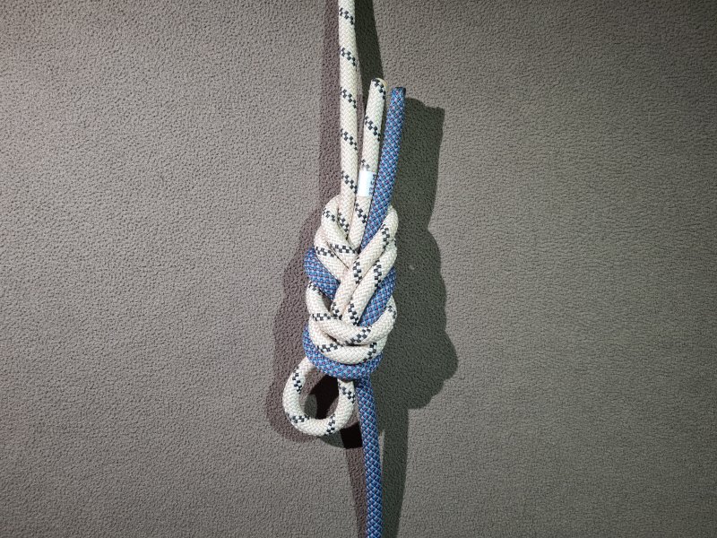
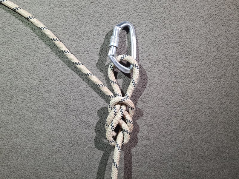
Avoid
A knot tied on a bight. Used to create a loop that can be clipped into a carabiner. Designed to be loaded on only one of its tails, directly away from the anchor, and is considered fairly strong when loaded that way. Can alternatively be loaded in three different directions at once, with two of those directions almost opposite each other, one pointing away from the anchor. Can be used where a traverse line changes direction. Sometimes used as one arm of a Y-hang, because it can be easily adjusted; this variation has the traverse line coming in to one side of the Y. However, this knot has some very serious shortcomings. Cross loading with a fairly low load, such as when someone clips a cows tail into the loop, causes the knot to capsize into a noose based on the figure of 8 knot, so that the loop rapidly enlarges, taking rope from the tail that comes sideways out of the knot. If the wrong tail of the knot is loaded, it can very easily capsize into a noose based on the figure of 8 knot, that tightens around whatever it is tied to, but then releases when the other tail is loaded (which it normally will be). For this reason, although it may be seen as part of a traverse line, it can only be used there if that tail will never be loaded. It must never be used at the start of a rope, to ensure that if it capsizes, it cannot fall off the end of the rope. When used as part of a Y-hang, it is less likely to capsize, since both arms would normally be under load at the same time, which forces the knot to keep its structure. However it can suddenly capsize if someone clips a cows tail into the wrong arm of the Y-hang, unbalancing the Y-hang, and removing the redundancy aspect of it. This might also happen when clipping cows tails into the loop, depending on how much load is applied to it, so neither side is safe. When used for a Y-hang, if the knot has capsized and the anchor that the knot is connected to fails, the knot immediately slips, causing a significant shock load, which competely defeats the safety aspect of a Y-hang. While this knot is sometimes used for rigging, it is a liability, and should absolutely be avoided. There are many better knots to use instead, such as an alpine butterfly knot, but the locked directional figure of 8 might also be a viable alternative. Made from a figure of 8 on a bight with one of the tails performing half a turn less than the other. Just like the figure of 8 on a bight, there is a version that is easier to intentionally untie after loading, and a version that is difficult to untie. The loaded rope should go around the shoulder of the knot (as shown in the illustration), not where the collar of the knot would have been. The rope that comes sideways out of the knot should be the one that would have formed the collar of the knot if it had been a figure of 8 on a bight.
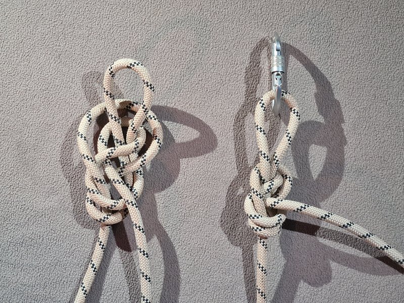
Probably good but needs more testing
A knot tied on a bight. A variation of the directional figure of 8 which does not suffer from the risk of capsizing when the wrong tail is loaded, and can be used in all of the same situations that a directional figure of 8 might be used. Both tails can be loaded either individually, or together, such as when using it for a Y-hang. It does not have such a neat dressing, but is easier to intentionally untie after loading than a standard directional figure of 8. Significantly more resistant to cross loading than a directional figure of 8 as long as it has been set correctly. If forced to capsize that way (which is unlikely to happen naturally), it becomes a variation of the butterfly knot based on a noose version of the figure of 8 knot, instead of the usual overhand noose. As a result, even the capsized version of the knot normally remains relatively functional. This knot has not yet been properly tested for strength, but relies on the same basic structures as the directional figure of 8 and butterfly knot, and is likely to perform similarly to those. In limited personal testing (using thin cord), it performed as well as a figure of 8 on a bight no matter how it was loaded (loading either tail separately, or loading across both tails without loading the loop). The main limitation of the locked directional figure of 8 is that it is harder to adjust than the directional figure of 8. Created by adding a single hitch around the loop strands of a directional figure of 8, like the one used by a butterfly knot, creating a half hitch structure. The single hitch is then tucked into the knot to prevent it from distorting the knot when loaded, before the knot is set. Relies on the directional figure of 8 to be dressed correctly, in the format that allows it to be more easily untied, to allow the single hitch to be tucked into place.
Common Recommended
A knot tied on a bight, with bunny ears (two loops), each of which can be clipped into a carabiner. The lengths of each loop can be easily adjusted, but the two ropes emerging from the knot cannot be easily adjusted. Designed to be used on a Y-hang. This variation has the traverse line coming in to the middle of the Y. More wasteful and less easily adjustable than a bowline on a bight. Repeated cross loaded may mis-adjust the lengths of the loops, and severe cross loading causes the knot to deform and lose some of its strength, or capsize into a form of the knot where the adjustment between the two loops passes freely between the loops, instead of being wrapped around the body of the knot. However, it generally performs better than a bowline on a bight when cross loaded. The knot has a detrimental quality that if one of the loops is disconnected from whatever it was connected to, that loop can pull back through the knot. With one of the loops, the knot will continue to function as a figure of 8 on a bight with one strand performing an extra turn, but with the other loop, the knot capsizes into a slipped version of a figure of 8 that can undo completely. If the knot has been loaded first, however, then it will normally tighten up and not allow the loop to pull back through the knot. Made from a figure of 8 on a bight with the loop fed back into the knot, and wrapped around the body of the knot, so that it becomes two loops.
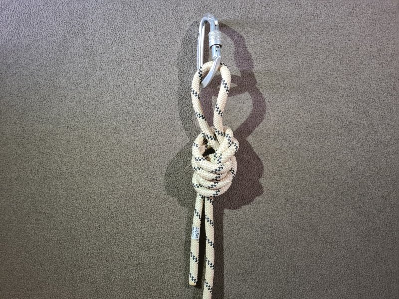
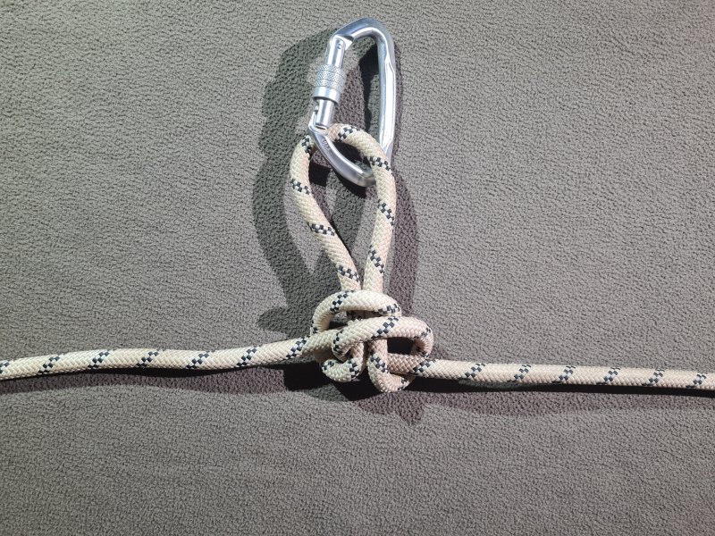
Common There are better alternatives
A knot normally tied on a bight, but can also be rethreaded. Used to create a loop that can be clipped into a carabiner. Designed to be loaded in three different directions at once, including perpendicular to the anchor. Can be easily adjusted and undone when needed. Can be used in the middle of a traverse line, and at a rebelay. Commonly used as one arm of a Y-hang; this variation has the traverse line coming in to one side of the Y. Can be used to attach a carabiner for a pull-through. Must not be used at the start of a rope, as it can undo if not loaded on one side. One of the strongest (when pulled against the loop) and least wasteful of all knots used in rigging. It is somewhat vulnerable to repeated cross loading before the knot has been set, and can capsize into a noose that tightens around whatever it was tied to. It is considered safe enough to clip a cows tail into the loop. Most of its benefits are surpassed by the Alpine butterfly knot, but the butterfly knot has the benefit that it does not introduce twists into the rope. Made from an overhand noose, with a single hitch creating a half hitch structure.
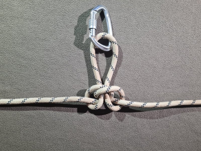
Common Recommended
A knot normally tied on a bight, but can also be rethreaded. A variation of the butterfly knot which outperforms it in most cases, and can be used in all of the same situations that a butterfly knot might be used. It is slightly stronger (not enough to worry about the difference), and highly resistant to cross loading. It does not capsize into a noose if cross loaded. However, it causes two full twists in the rope for every alpine butterfly that is tied (the butterfly knot does not). If tying several in a row, it can help to twist the first one clockwise, and the second one anticlockwise, and so on. This should help reduce the effect of them twisting, but can be confusing to do if they are tied by wrapping the rope around your hand.
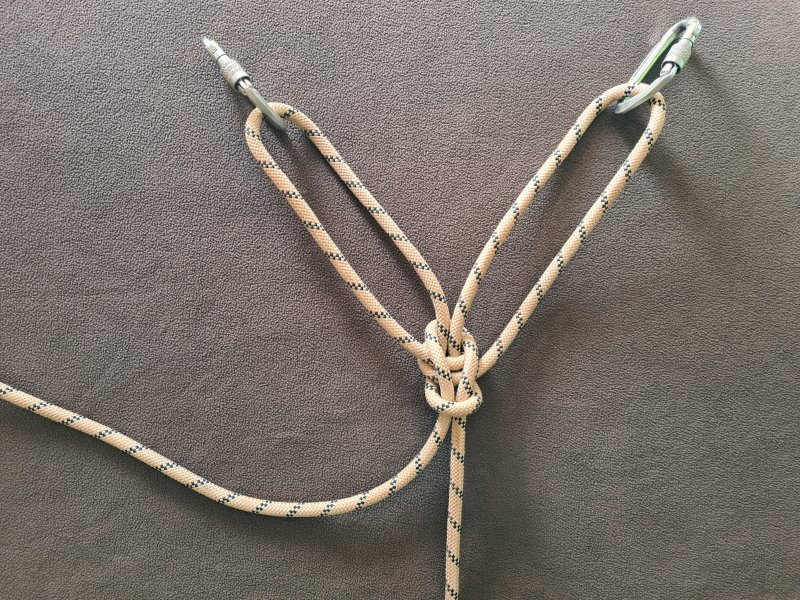
Avoid
A knot normally tied on a bight. It has two loops, and can be used as a bunny ears knot, and would work for a Y-hang. The lengths of the loops are very easy to adjust. Usefully, the two loops are held open by having a strand of rope passing through them, making them easy to clip into. Somewhat resistant to cross loading, although slow cross loading may cause it to look odd. Repeated or sudden cross loading may mis-adjust the lengths of the loops, or can cause the knot to loosen completely and capsize, and setting the knot tightly does not prevent it from happening. One of the loops is far more prone to this than the other (the one whose strand crosses over the outside of the other, where they cross over just before the loop). Because the two tails come from opposite sides of the knot, loading a tail causes the insides of the knot to rotate, scraping their strand against the strand that passes between the loops. Alternating which one is loaded, which will happen each time someone passes the Y-hang, causes a cutting action of the strands against each other, slowly damaging the rope. The effect is much worse with stiffer ropes. For this reason, the knot should be avoided. This knot could be confused with the double Alpine butterfly variation 2 and double Alpine butterfly variation 3, since they are all called by the same name. Made from an Alpine butterfly knot, with the two loops taken from part way around the knot, ending up with a structure made from two interlinked left-hand bowlines.
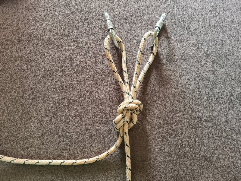
Avoid
A knot normally tied on a bight. It has two loops, and can be used as a bunny ears knot, and would work for a Y-hang, or can have the tails pulled apart, and used as part of a traverse line. However, the length of the loops is quite difficult to adjust, and the knot is very difficult to set. Cross loading or just pulling on a tail can easily cause the knot to capsize into a variety of different configurations, which can cause the lengths of the loops and the rope to change quite dramatically, even if it has been set tightly. This knot is not stable enough to be used reliably, and it should be avoided. This knot could be confused with the double lineman's loop and double Alpine butterfly variation 3, since they are all called by the same name.
A knot normally tied on a bight. A variation of the Alpine butterfly knot which has two loops. However, this cannot be used as a bunny ears knot, and does not work for a Y-hang, because the loops come out opposite each other. Highly resistant to cross loading, and does not easily capsize. Each loop can be used to pull separately against each tail, and the two tails can be pulled against each other, without the knot capsizing. However, the length of the loops is quite difficult to adjust. There are almost no practical situations where this knot would be useful, so it is never seen, but it could be confused with the double lineman's loop and double Alpine butterfly variation 2, since they are all called by the same name.
Avoid
A hitch tied by threading, that is sometimes used by mistake instead of a stopper knot. Provides no safety benefit, as it can capsize and untie itself more easily than the knot it is trying to protect. Can be thought of as a half hitch with its tail not fed through the knot. Alternatively, a half hitch could be thought of as a noose version of a single hitch. This knot should be avoided!
Avoid
A hitch tied on a bight or by threading, that may be mistakenly used to connect to a carabiner or anchor. However, it can slip when loaded, particularly if the object that it is tied around is able to rotate. This knot, and countless other knots taught in the Scouts, have no place in SRT. It is only acceptable in situations where a little bit of grip would be nice but not essential, and it would be acceptable for the knot to slip all the way until it unties at the end of the rope. It also is only acceptable if the person who ties it is constantly there with the knot, to monitor its slippage, and correct it if it slips too far to be useful. This means that it can have some purposes in climbing, and some very limited uses in caving, particularly setting up a Y-hang belay with a sling, where it cannot slip off the end since it is connected to an anchor at both ends, and gravity can keep it in position. With SRT, however, where ropes get left on a pitch to be used by others, and knots on SRT gear get dragged through a cave and pulled around in all directions, a clove hitch is a liability. However, it may rarely be seen connecting a set of cows tails to a D-ring, so that the lengths of the cows tails can be changed as needed, with one getting longer as the other gets shorter. In this case, it would be unlikely for the knot to walk off the end of the rope used to make the cows tails, since there is another knot clipped to a carabiner at each end of the rope, but they may randomly slip and change length while in use. Made from two single hitches.
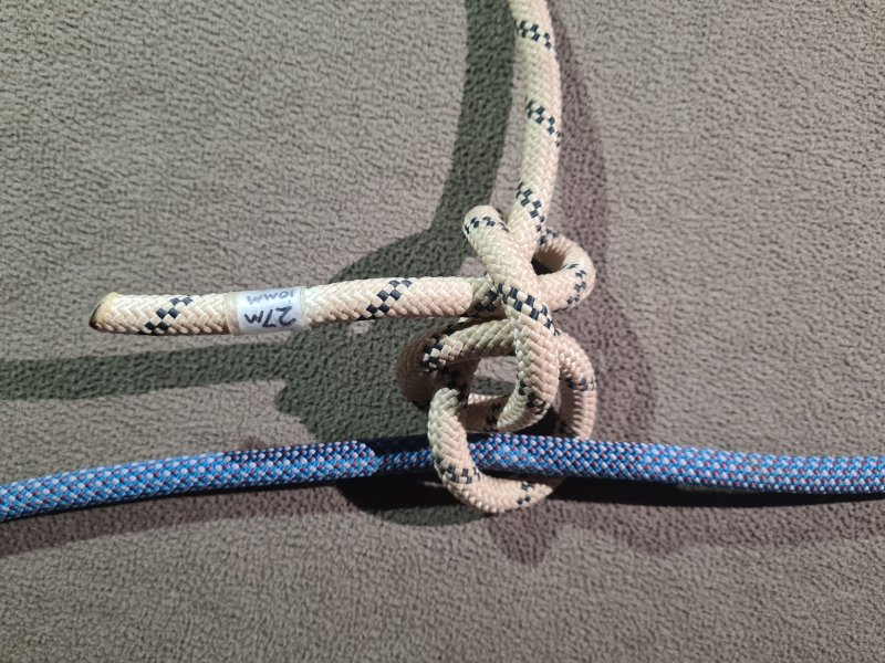
Avoid
A hitch tied by threading. Made from a noose version of a clove hitch, with all the same failings as a clove hitch. This knot, and countless other knots taught in the Scouts, have no place in SRT.
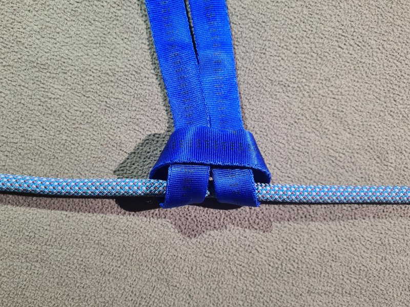
Common Use with caution
A hitch tied on a bight or by threading, that should almost never be used. Sometimes used as a way to connect a sling to a natural, but it would be better to simply clip both ends of the sling into a carabiner, which increases the strength by doubling the sling, rather than reducing it by adding a knot. With a nylon sling, it weakens the sling by 15-50% (nobody seems to be able to agree on the numbers, so it may relate to the width of the sling), but with Dyneema, it reduces it by much more, sometimes significantly over half (75% in some tests). However, it may be used if the sling needs to grip the natural more tightly to avoid slipping off. Users of this knot should be reminded of the disadvantages of its use. A doubled lark's foot does have some valid uses, such as turning a sling into a spreader, with the advantage that it reverts (without capsizing) to a doubled cow hitch (the same knot, but with only one side loaded) if one side is damaged. This must never be done with a Dyneema sling, however, because the knot can slip undone under load. Made from two opposing single hitches. If tied around another rope, it is the same structure as a reef knot or strop bend that has capsized. Climbers may be seen using a lark's X or clove X for similar purposes, which perform much better with Dyneema slings, but they are not seen in caving.
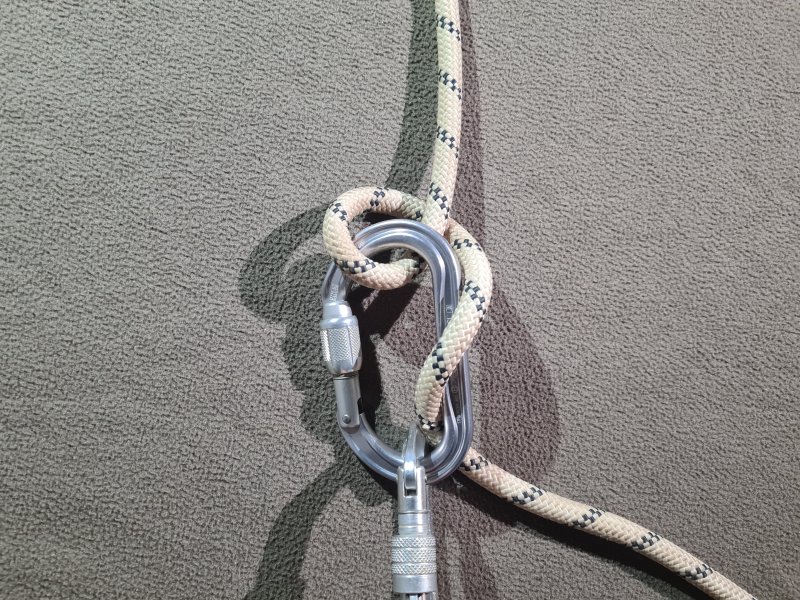
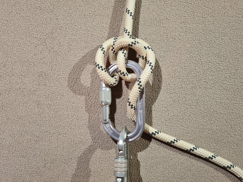
Common Recommended
A special type of adjustable friction hitch, tied on a bight, that lets you use a carabiner as a descender or belay device. Preferably a steel carabiner because it gets worn out quite quickly otherwise. Locking gates are essential. Increasing the tension on the down rope increases the friction, and slows the descent, just like a regular descender. Lifting the down rope up, so that it wraps further around the carabiner, also increases the friction. Twists the rope badly, so only used as a descender when needed/lazy. Often used as a belaying knot for a climb or ladder. The knot is bidirectional, and when pulled in the opposite direction along a rope, it will swing through the carabiner, reverse its direction, and perform the same task in the new direction. HMS carabiners are recommended because their shape and size is designed specifically for this purpose. For safety, the knot should be arranged so that the down rope is on the side of the carabiner away from the gate, if possible, since it can potentially unlock the gate by rubbing against it and catching on it. If the knot reverses because the direction of pull changes, the down rope will switch sides of the carabiner, so that in one direction, it will run against the gate, so this requires more care. When arranged so that the down rope is on the right side, exiting from the back of the carabiner (as it usually would be for a right-handed user), movement in either direction would normally cause a screw gate to tighten up no matter which side the gate is on. When arranged on the opposite side (as a left-handed user might do), or on the right side but exiting from the front of the carabiner, movement in either direction will normally cause a screw gate to unscrew. Users of this knot should carefully examine this motion to ensure that they use it in the safest manner. Made from an incomplete clove hitch or lark's foot.
There is also a "super" version of the knot, which wraps the tail of the knot back around the opposite side of the up rope in the same direction. This version is able to produce much more friction, and is therefore used for much heavier loads. This has the very significant benefit that it does not twist the rope like a standard Italian hitch while abseiling, though it introduces 2.5-3 full twists into the rope while tying it, compared with the Italian hitch's 1-1.5 twists, which can make it appear to introduce some twists when abseiling towards a rebelay. It can still change direction, but requires much more force to do so. If the second part of the knot is added to an existing Italian hitch, it switches which side of the carabiner the rope exits from, so the tail will now run against the gate when the Italian hitch would not have done. As a result, it is therefore best for the initial Italian hitch to have the carabiner clipped through it in the wrong direction for an Italian hitch, before adding the second part of the knot. However, it should still be tied in the same direction as the Italian hitch (as a right-handed user would usually do).
The knot is first thought to have been used by Phoenician sailors in around 1000 BCE (approximately modern day Lebanon), to control the launch of a ship. Much later, the knot became known as the crossing hitch, used to add a little extra grip where strings crossed when tying up a package, with the earliest known English depiction being from 1911. It was then used as part of a body abseil technique called the two leg seat, which was depicted in the 1913 edition of the mountaineering booklet Anwendung des Seiles published by the Bavarian section of the German Alpine Club, without giving any details about who invented it or when. It is not immediately recognisable in that format, but it used exactly the same principle, substituting the legs for the carabiner, and can therefore be considered the first time it was used for abseiling. The Italian hitch was then used by Russian climbers in the 1930s, presumably with a carabiner like it is normally used now. It was stated as being for belaying, but this could not be verified, since German mountaineer Pit Schubert made the statement in 1999 without providing a reference for it.
The knot was then depicted in 1944 by American sailor Clifford Warren Ashley as the crossing hitch in the Ashley Book Of Knots (#206, #1818), used to make a temporary circus fence. It had probably been used for decades for that purpose. It was then reinvented in Italy by Mario Bisaccia, Franco Garda and Pietro Gilardoni, in the late 1950s. It was intended to be used when initially securing boats to a bollard, reversing as needed to pull a boat closer, or to let it pull away. It was called "mezzo barcaiolo" ("half the clove hitch") in Italian, as it was an incomplete clove hitch. The German military used it for abseiling as early as 1966 for mountain rescue, and German military mountaineer Hans Hintermeier depicted it in their mountaineering regulations as the "Seilkreuzbremse" ("cable cross brake"). Swiss mountaineer Franz Ruso proposed its use for belaying in 1967, the way it is used now, but was ignored. It was separately recognised and used the same way by mountaineers in Italy's Valle d'Aosta for belaying by 1969. Swiss mountain guide Werner Munter is often mistakenly credited with introducing it to mountaineering, having learned about it while training as a mountain guide. The date of that is not accurately stated, but it is likely to have been 1969. He proposed its use for belaying in 1971, with the tail of the knot being held around the shoulders, which made it impossible to use as a reversible friction hitch and caused it to catch falls much more abruptly, so it was less useful for belaying, and this approach was abandoned. In the same year and at the same meeting, the Valle d'Aosta mountaineers tried to persuade the International Climbing and Mountaineering Federation (UIAA) to use the basic Italian hitch the way they had been doing, which is the way it is still used today for belaying, but it was rejected because it was incorrectly assumed the rope rubbing would damage it too much. Their much better use of the knot had nothing to do with Werner Munter, and had developed completely independently. The Italian hitch was probably first used for caving in Ghar Parau in Iran in 1972, by Iranian mountaineers who abseiled using it during the British expedition.
In 1973, after it was proposed again at a conference by the Italian mountaineers, Pit Schubert's safety group showed that it was safe to use for belaying, and during discussions between Pit Schubert and Werner Munter, it was given the German name "Halbmastwurfsicherung" ("half the clove hitch belay"), or HMS. The use of the Italian hitch had already spread to mountaineering around the World by the mid 1970s, and its emergence soon prompted the introduction of the HMS carabiner. Some climbers then (incorrectly) renamed the Italian hitch after Werner Munter, presumably because of his enthusiasm for it, and his own repeated incorrect claims to have introduced it to climbing, including arguments over whether he or Franz Ruso used it first. It really does not matter which of them used it first, because it had already been used for mountaineering over 50 years before either of them used it. Werner Munter's name is not appropriate for it, not only because he did not invent it, did not introduce it to mountaineering, did not use it the way it ended up being used, and was not the first to propose its use for belaying, but also because it only became accepted for belaying within mountaineering due to its proposal by Italian mountaineers, and then became popular because the UIAA recommended it, not because of Werner Munter. Being loud does not make you right. Most British cavers call it the Italian hitch.
This history section only covers the Italian hitch. This article also has a detailed history of many of the other devices and techniques that are used for vertical caving.
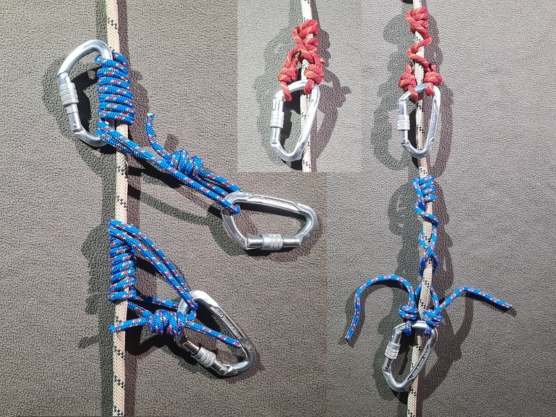
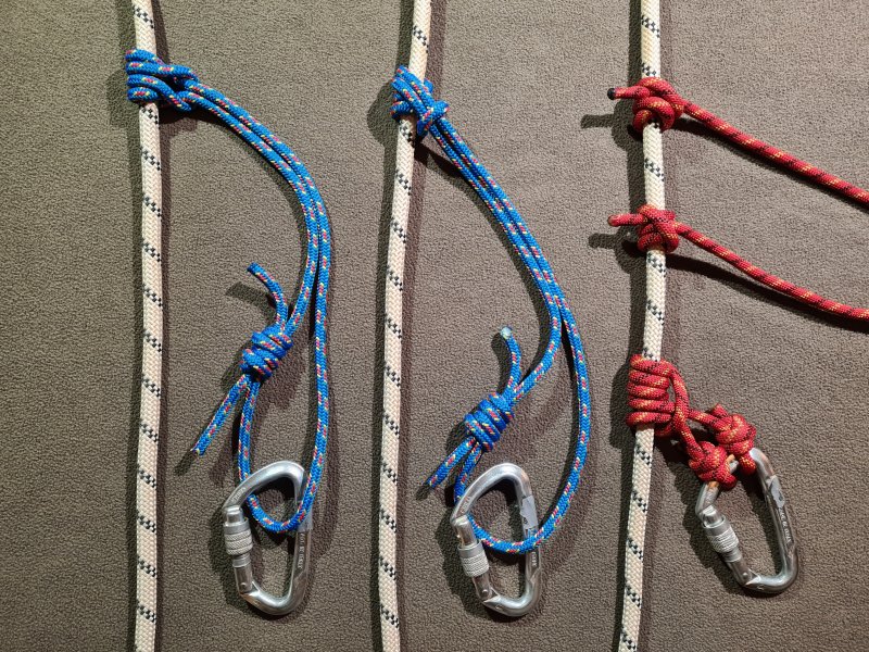
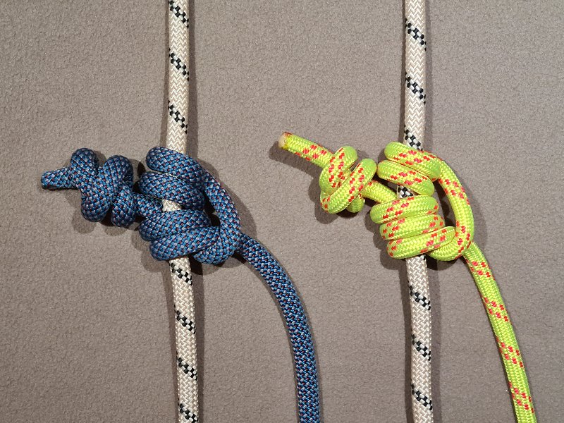
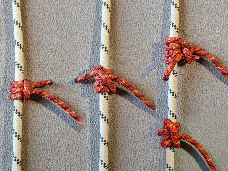
Useful for emergencies
Several different types of friction hitch which can be used instead of an ascender, and are commonly referred to as prusik knots. The klemheist knot (also confusingly known as the French Machard knot, despite not being French, and not being created by Serge Machard) is often used, and the classic Prusik knot is still regularly recommended, in spite of its problems. Both of those are made from a lark's foot with additional turns, but differ in which side of the knot the tails come from. Both can be tied with more turns or fewer turns, depending on how much grip is needed, and this can be used to set the working load limit of the knot. The Prusik knot can be frustratingly hard to untie after loading, and is less convenient for prusiking as a result, since it would need to be loosened for every movement. This problem gets much worse as more turns are added, and modern kernmantel nylon ropes normally require more turns than hawser laid and hemp ropes. In spite of there being several knots that perform better, it is still widely recommended by climbers, and appears in virtually all literature that discusses prusiking with friction hitches.
The Gérard hitch is a variation of the Prusik knot, where the carabiner is clipped into the loop at the ends of the knot rather than the middle, and is generally now only tied by mistake, but was the first one used for prusiking, and is slightly easier to tie. The Hedden knot is the original variation of the klemheist knot, and grips much better with only minimal turns. The Schwabisch hitch is an asymmetric variation of the Prusik knot, where one side of the knot has more turns than the other. The Bachmann knot does not grip as well on muddy ropes. The autoblock knot (also known as the Machard knot or French prusik knot, but that confuses it with the klemheist knot) slips more easily when accidentally touched even when loaded, and is intended to add more friction to a descender, not to be trusted for prusiking. Most of these knots are tied by threading a prusik loop around the main rope.
The Schwabisch hitch, Distel hitch, Valdôtain tresse and Valdôtain tresse XT are made from a tether instead of a prusik loop, typically connected using a pair of poacher's knots or eye splices, with both ends clipped to the same carabiner. The Distel, Valdôtain tresse and Valdôtain tresse XT knots are very rarely used, with the Valdôtain tresse XT needing a slightly longer cord, and significantly more rope than the other two. All three are based on the rolling hitch, with additional turns to provide a better grip. The Valdôtain Tresse and Valdôtain Tresse XT may need more wraps depending on the tether being used, and are often used in combination with a pulley to help push up the knot.
The Blake's hitch is made from a tether instead of a prusik loop, and is very unusual, because it can be tied with a tether that is the same thickness as the rope it is tied around. It is primarily used for doubled rope technique, where it only needs to hold about half the load it would do with regular prusiking, so the grip requirements are lower. With very flexible ropes, it is normally tied with four turns, and the tail is passed around the front of the tether, around the back of the rope, and fed up through the bottom 2 turns of the knot, known as a "4/2" arrangement. However, for stiffer ropes, such as the ones used for SRT, it usually requires more turns, and the tail needs to be fed through more of them, such as a "5/3" arrangement, with the knot being very tightly set before and during use. It relies on the tether being flexible enough to be able to bend in a circle of its own diameter, using just simple finger strength, and if the rope cannot turn a tight enough bend, then the knot will not grip enough. With most caving SRT ropes, it barely manages to get enough grip to be used for prusiking. The knot can slip untied, so a long tail is used, and must be tied with an additional knot that cannot slip back through the main knot, such as a double overhand knot. This additional knot also must be large enough to prevent the tail from passing through the loop running down the outside of the Blake's hitch, as even though that would cause it to pass through more turns, the knot does not grip unless the tail passes behind the main rope. Pulling on the tail can make it easier to slide up the rope. Because of its limitations, the main potential use of this knot in caving would be for some improvised rescue techniques.
The rolling hitch, Magnus hitch, steeplejack's hitch, locking hitch and helical knot are made from a tether instead of a prusik loop, with only a single end being loaded. None of these are likely to be actively used for prusiking now, and are mentioned here only because they played a part in the development of the more popular knots, or because they were historically used instead of the more common knots. However, the helical knot may see some rare use with prusiking in caves for historical fun, particularly in the southeastern USA, and the rolling hitch may sometimes be seen as the tautline hitch with tent guy ropes. The rolling hitch is just a clove hitch with an extra turn on one side. The Magnus hitch is a variation of the rolling hitch where the direction of the top turn is reversed, and is also a lark's foot with an extra turn on one side. The steeplejack's hitch is a variation of the rolling hitch with an extra turn. The helical knot is a more simple idea, relying on twisting the prusik tether around the main rope repeatedly, with additional turns increasing the friction. The tail is then tied to the loaded side of the knot to form a loop, typically using a bowline or eskimo bowline for caving, but a clove hitch might be seen in older publications. It is very common to add an overhand knot or figure of 8 knot in the tail of the bowline, to make it less likely to accidentally capsize, but this is definitely not as safe as using a stopped bowline. The helical knot is more sensitive to the knot being too lose or too tight, with it either gripping too tightly to allow easy motion, or not gripping enough to be used.
Almost all of these knots are directional, in that they are designed to be used only with a specific direction pointing up the rope. The exceptions are the Prusik knot, the Gérard hitch, the autoblock knot and the helical knot, which can be used equally in both directions. The Hedden knot and klemheist knot are inverted versions of each other, with the Hedden knot rarely neading more than two turns, and the klemheist often needing twice as many. For some reason, the weaker one became more popular, and people often incorrectly claim that the klemheist is weaker when pulled in the wrong direction. When using a hawser laid rope, many of the knots perform better when their turns match the twist direction of the main rope, and this is particularly significant with the helical knot.
Prior to the Gérard hitch, there were numerous hitches used by sailors, arborists and well diggers, such as the rolling hitch by 1794 and a variation called the Magnus hitch soon afterwards, which were used to secure objects to a cable, rope or mast, rather than actively prusik up it. Initially, the rolling hitch was also called the Magnus hitch until 1841, when the two names were separated, and the rolling hitch earned its own name (which had previously been used for a completely different knot, just to add to the confusion). Mountaineers were using friction hitches to secure ropes to an axe handle, described by British mountaineer Clinton Thomas Dent in 1892 in the Mountaineering magazine as a double clove hitch (though the exact knot is not known). They also used the rolling hitch in 1906, described by British mountaineer Lionel F. West as a way to connect ropes. However, neither of them were recognised as useful for prusiking. The classic Prusik knot and Hedden/klemheist knots were invented long ago by sailors who used them to raise a spar (wooden pole), depicted by American sailor Clifford Warren Ashley in The Ashley Book Of Knots (#1763 and #1762). The Autoblock knot was originally a well digger's hitch used to secure a hook to a pole (#505). It is not known exactly when each of these knots was invented, since the research for that book took place between 1933 and 1944, but the knots will have been in very common use already by the time they were researched, and the use of sailing knots will have come from the author's own time as a sailor, which began in 1904.
It is safe to assume that the Prusik knot was in use by sailors long before 1931, not least because Clifford Warren Ashley did not call it by that name or mention it in reference to mountaineering, showing that use of that knot within sailing had not originated with Karl Prusik. In addition, he stated that its purpose was for hoisting spars for sailing in particular, which was a dying art by then, as commercial and naval shipping had already been largely replaced by mechanical engines, and even hybrid sailing ships were being replaced with entirely steam powered vessels by the 1930s. (The last major cargo sailing ships to be built were the København and Magdalene Vinnen II/Sedov from 1921, though the major cargo sailing ships Pamir and Passat last sailed in 1957, and the smaller cargo sailing ship Omega sailed in 1958. Much smaller sailing ships are still made as pleasure craft or cargo carriers such as Indonesian pinisi.) However, Clifford Warren Ashley did not mention it in his minimalistic articles called The Sailor And His Knots from 1925 (which showed only a couple of hitches), so possibly he had not seen anyone using it in Massachusetts at that time, or did not think it was important enough to include. It will have originated as a lark's foot, which was used to attach a strop/strap or bale sling (a sling used by sailors) to a wooden mast or spar. This is always depicted as just a lark's foot in every manual I could find, starting with British naval manuals from 1860 and American manuals a few years later, but from as early as 1853, the text describing strops states that two or more turns could be used if needed for extra grip when attaching it to a rope with other hitches, implying that the idea of adding extra turns to a lark's foot might also be used if needed, creating the Prusik knot. Almost all sailing books from the 1800s and early 1900s simply copy each other's text and graphics, showing the subset of knots the British navy taught to new recruits. Very few had new content based on what was actually being used by sailors at that time and location, so they show only a fraction of the knots that sailors were actually using. As a result, it is impossible to know when the Prusik knot started being used by sailors. It might be that Clifford Warren Ashley was the first to depict it, but either way, it is likely to have been in use for many decades, possibly since the 1850s or even earlier. The vast majority of his 96 sailing knot references are from before 1931, and neither of the later ones show it, so it is extremely likely that he learned about it from a much older source. I have not been able to work out which one it came from, despite searching through the majority of them (a few of the old books cannot be searched, unfortunately). "What ancient hairy tar, how many centuries ago, was author of the artifice we do not seem to know." - Alan Patrick Herbert, The Bowline, 1939 (but that line could just as easily have been about the Prusik knot).
The Gérard hitch was created by French mountaineer E. Gérard and published in 1928 in French publication La Montagne, with more information later in the same year relating to footloops and glacier rescue, with the intention of it being used to ascend ropes, the first knot created for that purpose. Perhaps we should call it gérarding rather than prusiking, or even agripping, since mechanical ascenders came first. It is highly likely that he had also experimented with the Prusik knot variation, but preferred his own one. It is worth noting that almost every publication I could find that discusses this hitch incorrectly says that it was announced in the 1922 edition of La Montagne, but it was definitely the 1928 edition. It was translated into English in the Alpine Journal in 1929, as part of E. R. Blanchet's article "The Spare Rope In Theory And Practice". The Austrian mountaineering journal Österreichische Alpenzeitung described it in an article by W. F. in December of 1929, and referenced the Alpine Journal translation. Astrian mountaineer Karl Prusik would have read that journal, since he was a prominent member of the Österreichischer Alpenklub that published it (later the vice president of it), and which distributed both La Montagne and the Alpine Journal to its members, and it can be safely concluded that he knew about it. The classic Prusik knot was supposedly independently reinvented by Karl Prusik in 1931, inspired by the lark's foot which he had used to mend guitar strings in the World War I trenches. However, since it is basically the same as a Gérard hitch, with the load placed on the other end of the same structure, his invention was probably also heavily influenced by E. Gérard's article, though he completely failed to credit anyone, and significant parts of his article could almost be considered plagiarism. At the time, his clubs were openly racist, having been early adopters of what would later become Nazi ideals since 1921 (Karl Prusik himself served as a Nazi captain), and it is extremely likely that they would not have wanted someone from France to get the credit for developing something that they would end up using. Unlike the sailors who had normally pulled the knot directly away from the spar it was tied to, he used it to pull sideways, in line with the rope that it was tied to (this hardly counts as an innovation, and it is likely that sailors also pulled it this way, as books show they would sometimes do so with a lark's foot too). His name has since become an adjective and a verb, applied to all methods of ascending ropes, as well as the loops used to make the knots. His version of the knot has one fewer turn than is generally used now, and was more prone to slipping. According to his climbing partner Wolf Kitterle, he started work on it in the late 1920s, "he guessed 1928", and this is completely consistent with him having learned the technique from E. Gérard. These knots were then used as the main method of prusiking, even though mechanical ascenders already existed, until the first Jümar was released in 1958.
Some time before 1936, American arborists were using the rolling hitch and a variation with an extra turn, which they called a locking hitch, for storing their climbing progress. The rolling hitch also gets called a tautline hitch when it is tied back to its own rope, and American arborist Karl Kuemmerling was apparently using the tautline hitch for this purpose in the 1930s, probably as early as 1932, when he developed a sit harness. In 1938, French caver Pierre Chevalier used the Prusik knot to prusik up a pitch in the Dent de Crolles system after a ladder failed to pull up correctly, which is the first known use of a friction hitch underground. By 1944, American steeplejack Laurie Young showed that they were also using a variation of the rolling hitch called a steeplejack's hitch. American arborists were also using the prusik knot by that year, but pulling on one side of it instead of using both sides at once. This seems to be an independent invention, derived from the locking hitch. By 1952, American cavers Bob Handley and Charlie Fort had also used Prusik knots in caves. The Bachman knot was invented by Austrian Franz Bachmann in 1952. In 1955, British caver W. H. Little created the Slipgrip, a belay device for self belaying, which relied on a simple helical friction hitch. This was very similar to a well digger's hitch (#1760) described in 1944 by American sailor Clifford Warren Ashley, but using a splice instead of its final clove hitch. American caver Chet Hedden reinvented the Hedden knot and klemheist knot (the same knot pulled in opposite directions) in 1959, and decided that the Hedden knot direction was better because that direction did not jam, and resulted in a much more natural direction for the tails to be pulled. After it was announced to cavers in 1959 and climbers in 1960, others chose to use it upside down, in the klemheist direction, even though it was weaker in that direction, and often needed more turns. The inverted Hedden knot was named the klemheist knot in 1973 in Bill March's Modern Rope Techniques, and people soon forgot that it was much better when used in the Hedden knot direction.
American caver Clarence Cook is credited with inventing the helical knot (later known as the Penberthy hitch after Larry Penberthy reinvented it in 1968) in 1961, but it is the same basic knot as the Slipgrip used 6 years previously, relying on a bowline to tie the ends together instead of a splice. The autoblock knot was reinvented in France in 1961 by Serge Machard, which happened to be an adaptation of the inverted Hedden knot. At the time, it is likely that he did not know about the existence of the Hedden knot. Because of their similarities, and because they both started to be used for mountaineering at around the same time, the name Machard was used for both the autoblock and klemheist knots in French, and because of that, many people mistakenly assumed that Serge Machard invented the klemheist knot too. In 1963, British caver T. Charles Bryant stated in the Wessex Cave Club journal that the Austrian Alpine Club had said that the Prusik knot did not work well enough with nylon prusik loops, especially when wet, and that the Bachmann knot was better, and that hemp was a better material for prusik loops when used with the Prusik knot.
Arborists and cavers then made numerous little variations of the rolling hitch, often adding turns and tucking the tail through various parts of the knot. The Schwabisch hitch was announced as a new invention by Bernd Strasser in Germany in 1998 for arboriculture, but it is a variation of the Prusik knot that had actually been in use since the 1970s, and is also a variation of the much older Magnus hitch. The Blake's hitch was created in 1981 by Austrian mountaineer Heinz Prohaska, when it was announced to mountaineers, and announced to cavers in Nylon Highway in 1990. However, when it was then used and described by arborist Jason Blake in 1994, it was renamed by arborists to the Blake's hitch, and the incorrect name has now become its common name. (Heinz Prohaska is also the author of the 1997 article that exposed Karl Prusik's deception, so it is almost insultingly ironic that he would be deprived of recognition over his own invention. A sarcastic bravo, arborists.) The Valdôtain tresse was invented some time before 1994 in Aosta, Italy, for use with Alpine search and rescue. The Distel hitch was created from a mis-tied Schwabisch hitch. As might be expected, several variations of each of these knots were produced, often with someone's name or initials attached to them. And there are numerous other knots that are not related to any of these, many of which appeared and disappeared from use during the days before Jümars became available.
This history section only covers the Prusik knot and other friction hitches. This article also has a detailed history of many of the other devices and techniques that are used for vertical caving.
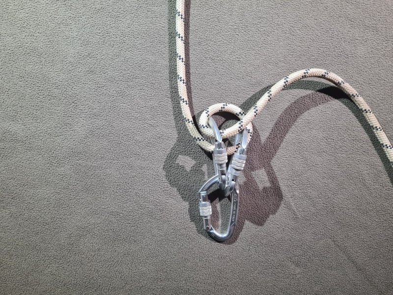
Useful for emergencies
Friction hitch used to create a chest jammer when a real one is not available, instead of using a prusik knot. Much more clumsy to use, as the down rope needs to be pulled upwards for it to feed through. Usually grips and releases the rope very easily, but often takes some time to grip, so a lot of effort can be lost. Sometimes locks up and needs some effort to make it release the rope. Cannot create a top jammer. Needs a perfectly matched pair of locking carabiners. It can also work with snap-link carabiners, and in fact works a little better because the carabiners can get closer so they can pinch thinner ropes better, but with the obvious risk of it accidentally opening the gates during use. It is more likely to accidentally open screw gate carabiners if the rope is fed in one direction through the carabiners rather than the other, so twist locks are best. Otherwise there is a chance the rope can accidentally rub the screw gates in the direction that unscrews them, open the carabiners and either disengage the knot, or disconnect them from the rope! It relies on the strands of rope crossing over each other to get the best gripping effect, so it performs best with carabiners that channel the rope into the corner, such as a D-shaped or offset D, but it can be used with oval carabiners too. It does not work well with pear-shaped carabiners, as it can slip into a position where it does not grip at all. For the most reliable use, the two carabiners should be held quite firmly together, with a common recommendation being to connect them using a sling tied around both of them using a lark's foot, which tightens when loaded. Made from a very simple loop that binds the carabiners against each other when pulled in one direction. Twists the rope badly.
A self belay device from 1955 functioned the same way as an Alpine clutch, though it involved a box with moving parts. It was created by British caver W. E. Clarke. The Alpine clutch was created by Italian Franco Garda in 1970 (the same person who used the Italian hitch for shipping). It was appearing in British caving articles in 1977.
This history section only covers the Alpine clutch. This article also has a detailed history of many of the other devices and techniques that are used for vertical caving.
Avoid
A binding knot tied by threading, used to tie up the top of a tackle bag, one of the very few things it is actually good for. Made from a pair of half knots, with alternating overlap directions. Used in a very careful arrangement of multiple knots that prevents the reef knot from untying with an amarrage souple. Sometimes used as a bend knot to join two ropes to make a longer rope, but only when combined with a double fisherman's knot for safety. With only a single pull on one of the tails, a reef knot can very easily capsize into a lark's foot tied around a tail which can then slip off and untie completely. It also reduces the strength of the rope significantly (as much as a 75-90% reduction in strength). As a result of both of these major failings, this knot should be avoided (except for the very specific use of tying up the top of a tackle bag). This knot, and countless other knots taught in the Scouts, have no place in SRT. This is a very dangerous knot!
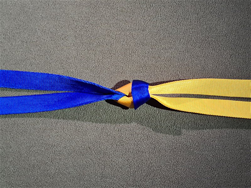
Recommended
A knot used to join two slings to make a longer sling, while retaining about 80% of the strength of the sling. Works best with nylon slings or wide Dyneema slings. Narrow dyneema slings or a mix of Dyneema and nylon slings, reduces the strength of the sling to about half. If a sling is cross loaded, this can capsize into a lark's foot. Made from a reef knot or capsized lark's foot. Despite being related to a reef knot, it is far stronger, since all four strands are being pulled equally, and the knot cannot capsize into a form that slips undone.
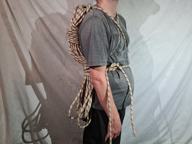
Common Recommended
A coil used to bundle ropes up for storage, transport or drying. Uncoils without twists, and rarely causes tangles. A few different variations for how to tie the loose end, usually started with a doubled rope. Some start with the two ends of the rope in your hand, some start with the middle of the rope in your hand. Some variations allow the coil to be worn as a backpack, some allow it to be hung on a peg, others use the final turn to bind the coil, leaving the binding around the coil without an obvious tail. The "wow" coiling method starts with a single strand, and normally allows the rope to be used without uncoiling, as it normally pays out like a flake (but sometimes it does not, so it cannot be relied on).
Common in USA
A method used to tie a rope to a natural as part of the indestructible rope technique. This method preserves the maximum breaking strength of the rope, as it does not rely on the final knot to provide any of the strength. The rope is wrapped multiple times around a large natural, such as a tree or boulder, with the rope only turning large radius bends. The natural should be at least 8 times as thick as the rope, and bigger is much better. After several turns, the friction provides enough grip for the rope to provide its full strength. The exact number of turns will depend on the friction of the rope and how smooth the object is that it is being wrapped around, but 4-6 turns is normally about right. This can waste a very large amount of rope, depending on how large the natural is, and how many turns are needed; 20 metres of rope could easily be wasted on a single natural. The tail of the wrapped rope is then tied in a hitch or loop knot, either threaded directly around the loaded rope, or with a carabiner that is clipped into the loop, and around the loaded rope. When threading the knot around the loaded rope, it is common to use a bowline (a format known as a "running bowline", but with the tensionless hitch tied in the noose of the running bowline). When using a carabiner, is is common to use a figure of 8 on a bight. However, many other knots could be used for this purpose. The connection to the loaded rope is only used as a safety measure, just in case there is not enough friction, and to prevent people, animals, wind or water from unwrapping it unintentionally. If it has been configured correctly, the final hitch or loop knot is not loaded at all, and does not provide any of the strength. It can actually be left hanging loosely, which is why it is called tensionless, since the final knot is not put under any tension. This technique is not used at all in Britain, and is almost exclusively used in parts of the USA where indestructible rope technique is used. The terms come from the USA, and there is no British equivalent.
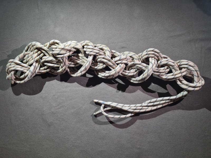
Common Recommended
A coil used to bundle ropes up for washing in a machine, since it is less likely to accidentally undo than most other coils, and is less likely to trap dirt in the bundle. Uncoils with kinks and twists (if the chain is made from single direction loops), and often causes tangles while uncoiling; very frustrating to uncoil a rope at a pitch head. Often started with an overhand noose, but with a doubled rope, it can be started with a lark's foot instead. Usually replaced with a butterfly coil for drying and storage.
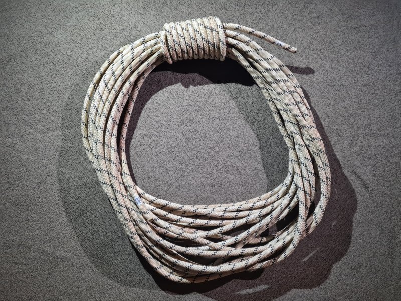
Common
A coil used to bundle ropes up for carrying in a loop around your body. Uncoils with twists, often causing tangles. However, it is possible to use the "over under technique" to reduce twists. Only suitable for shorter ropes such as handlines.
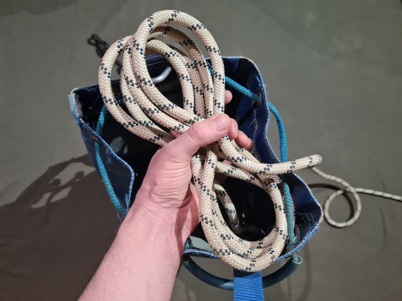
Common Recommended
A flake used to put a rope into a tackle bag so that it pays out (feeds out) cleanly while abseiling. Usually done while preparing for the caving trip, not while underground.
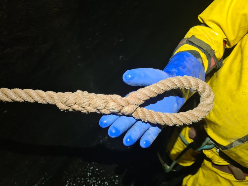
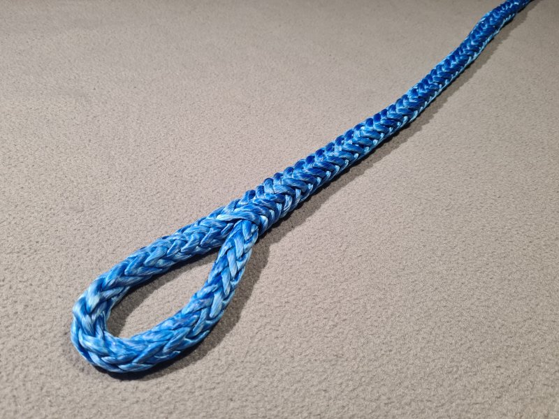
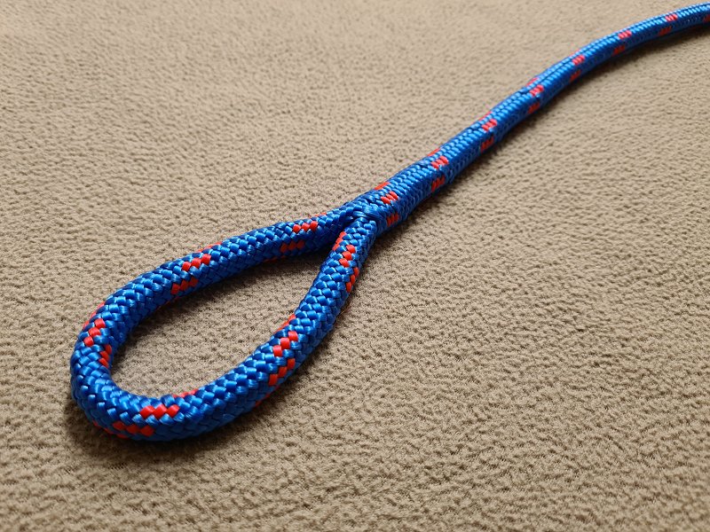
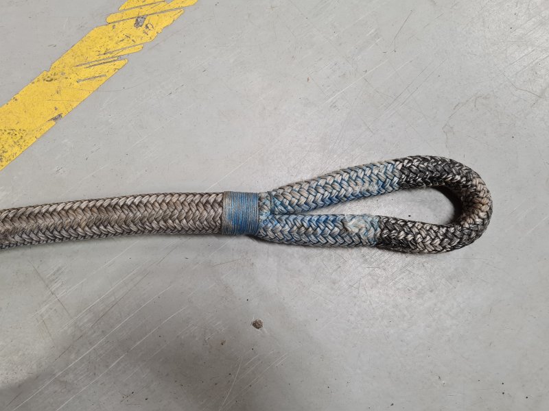
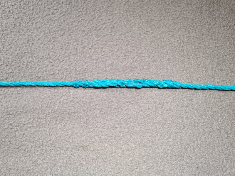
A way to connect ropes to each other or back to themselves, without using a normal knot. The most common use is to form a loop known as an eye splice in the end of a rope. The second most common use is to join ropes to make a longer rope without using a bend, known as an end-to-end splice, such as the short splice and long splice. There are several other less common splices which are tailored specifically to hawser laid ropes, such as to fold the end of a rope back on itself rather than tying a knot or melting the rope to prevent it fraying, known as a back splice or end splice. Loops can also be made while joining ropes, known as a cut splice or horseshoe splice. Specially shortened versions of the eye splice can be used to connect to chains and rings, known as a chain splice or ring splice.
With most types of splice, the individual strands of two pieces of rope, or two parts of the same rope, are woven around each other in such a way that the individual strands grip each other using friction, rather than the entire rope at once like a normal knot. They normally require the rope to be partially deconstructed and rebuilt into the splice. Because of this, a splice is not normally considered to be a type of knot, in British English. Almost all splices require the end of at least one rope to be used, so they cannot be used to make a loop part way down a rope, and they cannot be used to join two ropes part way along both of them. Although there are many types of end-to-end splice, most have the disadvantage that they make the rope much thicker, which limits their uses, though there are some that only make it slightly thicker, such as the long splice (which can only be used with hawser laid ropes). As a result, eye splices are more common than end-to-end splices. With most types of rope, splices are extremely time consuming to prepare, are designed never to be undone, and often cannot be adjusted after they are made, so they are never used for rigging. They might be used in rare cases with pre-prepared equipment such as commercial prusik tethers or fixed handlines, but they are much more common with arborist, highlining and sailing equipment, where abrasion is less of an issue.
With hawser laid ropes, the strands are woven through each other, using a tool called a "marlinspike" or "marlingspike". With braided/plaited ropes, it is normal for one of the ropes to be fed through a gap called a "neck" or "throat" into the hollow middle of the other rope, with a long length buried inside the other rope, relying on the Chinese finger trap effect from the outer rope to grip the inner rope (this is most commonly used with Dyneema cords). For end-to-end splices, both ends could be fed into the middle of the other rope. With braided/plaited ropes, splicing is used almost exclusively to create eye splices, so the two ropes are really just different parts of the same rope, at either side of the loop. The buried length is normally about 20-30 times the diameter of the rope, so for a 10 mm rope, the bury length will be about 20-30 cm, but it can be as much as 72 times the diameter of the rope with Dyneema. This is normally fed through the outer rope using a tool called a "fid". Some strands of the inner rope are normally cut to different lengths to produce gentle tapers instead of abrupt changes, to preserve more strength. Splices in braided/plaited ropes are often protected with a whipping made from thinner thread which is lock stitched through them and wrapped around them, to prevent the splice from slipping when not loaded, or when repeatedly loaded and unloaded. With double braided/plaited and kernmantel ropes, it is normal for complex picking and unpicking to be required, weaving the core and sheath of one rope separately into the other rope, relying on the same effect as the braided/plaited rope, but in several different steps. Again, this is used almost exclusively to create eye splices, and in many cases, the core and sheath are passed around the eye in opposite directions to each other.
There are many different variations of each type of splice, many of which are tailored to specific types of rope manufacture. Some will work only with ropes that have a specific number of threads making up their sheath or core. Some manufacturers specify their own recommended splices which perform best for specific rope products. Splices typically take up much more length than a knot, so it is not possible to make a short tether using them. The part of the rope taking part in the splice remains relatively thick and stiff compared with the rest of the rope, and loses most of its dynamic properties, which can be inconvenient for some purposes. Splices have the benefit that they retain about 80-90% of the minimum breaking strength of the rope, or 100% with braided/plaited Dyneema. Note that with hawser laid rope, the stated strength of the rope is typically tested with an eye splice at each end which itself retains about 90% of the strength of the rope, so a short splice in the rope is often said not to reduce the stated strength, even though it actually does (a long splice retains about 85-90% of the stated strength, so 77-81% of the actual strength of the rope). However this strength will depend on the specific splice being used, and how well it has been made. For example, the strength of an end-to-end splice is improved if the splice causes the tails of both ropes to be kept under tension, which improves that rope's grip on the other rope. Without that, a much longer splice is needed to obtain the required amount of grip. Natural fibre ropes such as hemp generally need shorter splices than synthetic fibres such as nylon, and slippery fibres like Dyneema need far longer splices. Eye splices are extremely poor when cross loaded, and can fail at extremely low loads, such as just 3-15% of the strength of the rope, even in cases where the splice is extremely strong when loaded normally. This is low enough that they could fail just from the load of a person hanging on the rope. Eye splices should never be cross loaded.
Splices rely on the sheath of a kernmantel rope to grip the rope strands. As a result, a damaged sheath can cause the strength to be lost completely, which is a serious problem in high abrasion environments like caves. In general, kernmantel ropes are not considered to be good for splicing even in low abrasion environments, though a few splices have been developed for them. In some cases, splices that appear to have been used with kernmantel rope are actually intended for use with braided ropes that have either a hollow core or some filler core strands which are there to make the rope have a rounded shape, rather than providing strength. Those splices may abandon the core strands completely, while performing the splice only with the sheath. It is extremely dangerous to use any of those splices with actual kernmantel rope. Splices are far more common with double braided/plaited ropes, since both the sheath and core braids can take part in providing the grip of the splice, but they are still significantly weakened by a damaged sheath, and are not really suitable for caving. In some cases, a splice in double braided/plaited rope may still abandon the core braid while briefly interlocking the core and sheath braids, and rely only on the sheath for strength around the eye, but this can only be used on ropes where the sheath is strong enough. This type of splice remains weaker than one using both the core and sheath around the eye, but can make the splice more stable when repeatedly loaded and unloaded compared with a splice where the core and sheath are not interlocked, and this approach may be used in places where the splice needs to remain very thin or flexible, such as some arboriculture cases.
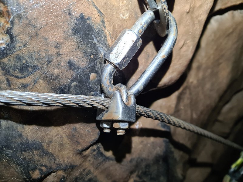
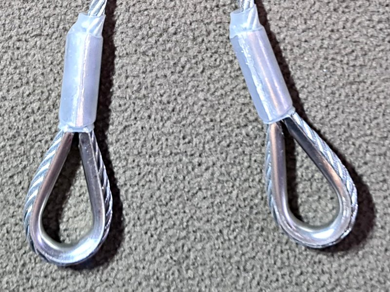
When working around pitches, there is often a lot of noise from falling water and echos. Cavers must communicate over relatively long distances. The standard calls are intended to enable communication over these distances, with minimal chance of being misunderstood. It is important not to use the wrong calls, or to mix up calls. For example, "take in the slack" can leave a belayer questioning whether you wanted them to take in, or give you slack, and can result in dangerous confusion. "Help me" sounds a lot like rope free, and could also result in dangerous confusion. With bigger pitches, walkie talkie radios might be needed instead, to allow proper communication.
Communication with whistles is very limited compared with the standard calls. There is no way to ask for slack, a tighter lifeline, or state that the rope is free. Therefore cavers should discuss these calls amongst themselves, and work out which calls will be used for what purpose. The following calls are generally understood, but since there is no real need to have both an up and down call in use at the same time, one of them might be re-purposed to state that a rope is free, while the other can then be used for something else.
Several parts of this article cover the historical development of equipment or techniques. To help you find them all, they are listed here:

While researching this article, several examples of statements that are commonly repeated as "facts", turned out to be myths or mistaken assumptions. By far, the biggest of these is about the origin of carabiners, as virtually all sources, including carabiner manufacturers, get it wrong. To make it easier, I have gathered them all here:
The most hazardous part of any caving trip is the part before it where you cross a street, or the parts where you drive to and from the cave. That is not to say that vertical caving is not hazardous, but hopefully it should help to put things into perspective. As humans, we are quite poor at judging danger, and tend to think of things as dangerous just because we are unfamiliar with them. In reality, the hazards of daily life far outweigh the hazards of cave exploration. At least with vertical caving, we put a lot of effort into minimising the hazards, far more than we do with most other sports or common daily activities.
With vertical caving, there are many of the same potential hazards as in regular caving, but there are a several that are unique to the vertical nature of the cave, which must be avoided by rigging the ropes or ladders away from the hazards, or providing protection. This section is not intended to be an exhaustive list (this page is about terminology, after all), but this shows why the approaches and equipment described on this page are used.
Many hazards can be avoided by good rigging. The heights and slippery surfaces can result in falls, and need protection. The dropzone for shrapnel and equipment from cavers, idiot tourists and streams, needs to be avoided where possible, to protect both cavers and the equipment. Falling sheep can sometimes happen with surface shafts! Rigged routes should avoid loose debris where possible, as well as birds' nests in surface shafts. Waterfalls are a common hazard which can make breathing difficult and rapidly reduce body temperature if not avoided. Fast flowing water at the head or base of a pitch is a hazard of its own. Deep water, such as sumps or lakes, does occur at the bottom of pitches in some caves, and rigged routes should not normally land in it. Spikes of rock, or pointed stalagmites sometimes occur at the bottom of pitches, and these need to be avoided. Rub points can rapidly cause severe damage and even cut through a rope, which can be avoided with Alpine rigging, or reduced using rope rub protection. Confusing rigging can cause cavers to make mistakes, such as getting hung up, accidentally abseiling off the short end of a rope, or following the wrong rope when a pitch has ropes rigged over each other. Selecting a good rope diameter and pre-shrinking it or wetting it before use prevents it from being so fast that someone might lose control of their speed while abseiling. Preparing the rope correctly can also prevent some other hazards. Packing the rope correctly prevents the rigger from having to contend with spaghetti. A safety knot prevents a caver from abseiling off the end of the rope.
Some environmental hazards can happen in spite of good rigging. Fear of heights can be a significant risk if it causes someone to act irrationally, forget their training, or shake so much that they cannot use their equipment. Cold can be excessive, due to the amount of time spent waiting for rigging while in a wet and draughty cave, without anywhere to go to warm up. Sitting in a sit harness for too long without moving can cause suspension syncope, which can happen while waiting for a rigger without having anywhere good to stand, or can happen to an incapacitated casualty. Loud sounds from water and big hangs can make communication challenging or cause confusion, but whistle calls can help with this to some extent, and walkie talkies can help a little more. Flooding is something that can happen particularly quickly in many potholes. Very narrow pitches can prove challenging, particularly given the movements required for prusiking.
Training can help avoid a lot of hazards. Failing to use the equipment correctly, or follow the right procedures, can have serious consequences, so training is essential. Sit harness buckles and carabiners should be checked to make sure they are closed. Failing to connect to a rope correctly can result in a fall. When abseiling, it is very easy to forget to look down and watch out for hazards which can cause injury or snagging of equipment. With long hangs, where the weight of the rope changes the friction during the descent, additional friction might need to be added part way down the hang to avoid losing control. Body parts could be entangled in equipment which is not used correctly. Hair can be abseiled into a descender, and may need to be cut free, using a knife next to the rope while unable to see it.
A great deal of effort is made to make sure there is redundancy, such as almost always having two points of contact with the rope, which mitigates a lot of potential hazards and mistakes. The exceptions are that a single descender is normally used (though climbers are sometimes seen using a shunt or prusik loop as a safety brake), a single sit harness is used (though these do have minimal redundancy), a single D-ring is used, and a single rope is normally used; if one of these fails, there is normally nothing left, so they are typically over-engineered.
Extra challenges are presented by the existence of caving and SRT gear, and selection of approapriate equipment can help avoid this. Swimming across pools while wearing SRT gear is challenging, and needs additional buoyancy. Carbide lighting (where still in use), is not only environmentally questionable (hello pile of spent carbide) and unintentionally vandalising with its pervasive soot marks, it is also a significant fire risk, since there is a flame dancing around on your head right next to a rope, and you cannot see where it is pointing.
Equipment can be damaged or fail. Anchors, naturals, tat and knots can fail, resulting in shock loading as other equipment takes over, impacting the floor or a ledge, or a fall if there is no suitable backup. Even if they do not result in a fall, an accidental pendulum may result in impacting a wall. Passing cavers could dislodge a sling that has been looped around a natural (particuarly common with deviations), exposing the caver to whatever hazard the rope had been set up to avoid. Equipment can become worn out or fail, and needs regular inspections before and after each use to ensure that it is still safe. Weak or fractured rock could break, dislodging an anchor which was placed in that piece of rock. For all of these reasons, rigging normally includes multiple backups and Y-hangs, configured to reduce shock loading.
Ropes exposed to heat or UV from sunshine, or many types of cleaning chemicals, deteriorate relatively quickly (this applies to slings and sit harnesses too). Ropes left dangling in a waterfall for several weeks or months can become damaged because of the constant movement, expecially if they frequently make contact with rock. Unused ropes eventually deteriorate over time (though nothing like as fast as previous maintenance schedules would suggest). General use of a rope slowly wears it out. Mud and ice on a rope can cause the rope to become damaged faster, and will also wear down other equipment much faster. They also make it hard for ascenders to grip the rope. Hot descenders can singe or partially melt through a rope, and ropes may be intentionally wetted to avoid this risk. Ropes could be stressed by having two many cavers connected to the same piece of rope, such that their combined weight is held by the same knot. Ropes could also be stressed by tension, such as with a Tyrolean traverse, or by using knots that dramatically reduce the strength of the rope.
Equipment could be stressed in unexpected ways, such as being bent around a rock, or pulled in an abnormal direction, causing it to deform or break. Handled top jammers are the most common case, bending them around a rub point at a pitch head; yet another reason why rub points are bad, and indestructible rope technique should be avoided. Poorly placed anchors could cause extreme stress by pulling on the screw threads, or can cause a knot to rub against the rock at the anchor. Unlocked carabiners could have their gates pulled onto something, causing them to open. Carabiners and maillons could be accidentally left open, causing them to break or release a rope.
Almost all equipment is designed to cope with 5-10 times as much force as it should ever experience during normal use, with a minimum breaking strength normally 5 times more than the recommended working load limit. The seemingly excessive over-engineering of equipment, and repeated use of redundancy, is what allows issues to happen without serious results. A rope being parially worn through by a rub point, a carabiner being bent sideways over an edge, or loaded repeatedly at high loads. Some rock fracturing and taking an anchor with it, suddenly shock loading the rope as it now has to catch the rock as well as supporting the cavers who were above and below it. It might not ever happen, but if it does, the equipment can cope with far more than just a normal load.
Somewhat less obvious and thankfully less common, a thief could take the ropes or other rigging equipment, leaving cavers stranded. A vandal could damage the equipment, leaving the rigging in a dangerous state. Thieves are somewhat dissuaded by tying the bottom of a rope to something on a surface shaft, so that they cannot pull the rope up from the top.
.jpg)
.jpg)
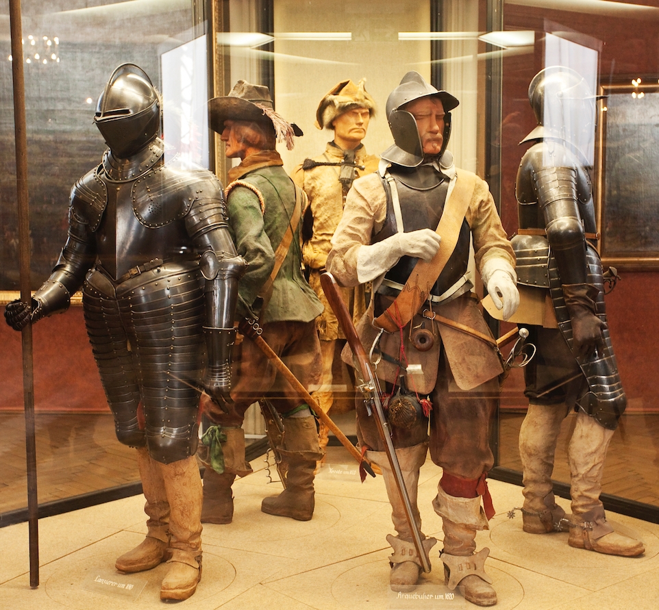
.jpg)
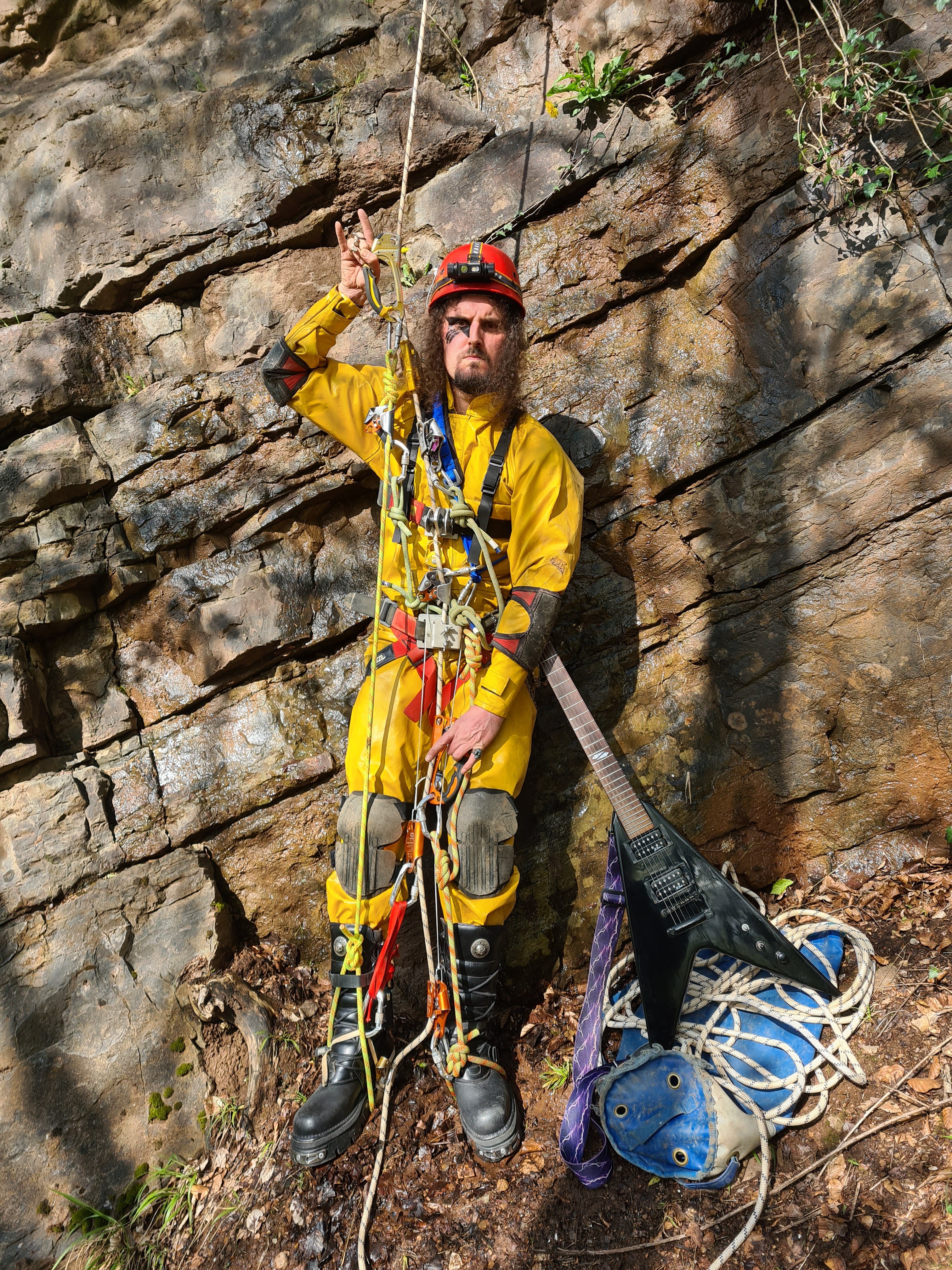
.jpg)
_351.jpg)
_b_049.jpg)
_b_517.jpg)