
Vertical caving terminology and methods > General hardware
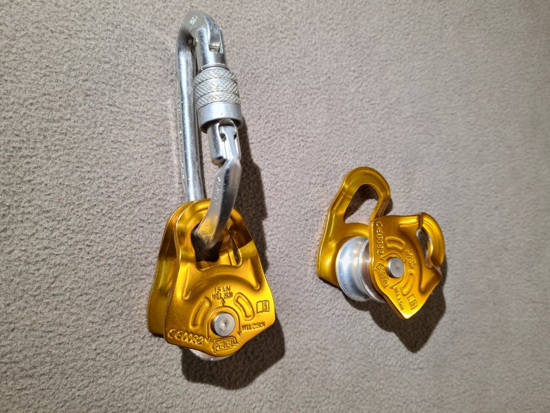
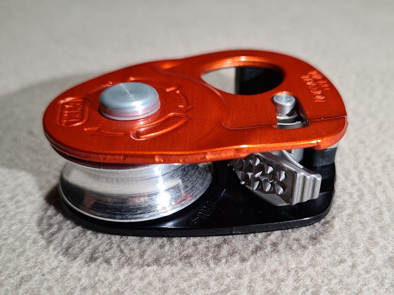
A wheel ("sheave") that the rope can run over, providing much less friction than if it just runs through a carabiner. In site of their benefits in many situations, it is more common to simply run the rope through a carabiner, and pulleys are generally reserved for a few specific uses. There are several variations, including dedicated pulleys with a housing that can be clipped to a carabiner, down to a basic wheel that is put onto an oval carabiner, using the carabiner as its axle. Most designs have to be removed from the carabiner they are attached to, in order to connect or disconnect them from a rope, and a keeper cord may be needed to avoid dropping them. Some have fixed sides, where the rope needs to fit through the gap between them, so they need to be used with a wide carabiner which pulls equally on both sides, so they work best with an oval carabiner. With fixed sided pulleys, other carabiners designs, such as D-shaped, can cause unequal or diagonal loading that may damage or break the pulley at surprisingly low loads. Many pulleys use swing cheeks, where the two sides can be rotated separately, allowing them to be separated to get the rope between them, and these tend to have no gap when closed, so they can work with almost any design of carabiner. Lightweight, small designs are often preferred, but the strength requirements may sometimes mandate larger pulleys. Some designs have a cam like an ascender which allows the rope to move only in one direction, specifically for use with hauling, and are known as progress capture pulleys. Many of these can also be used as an ascender.
A pulley may be used to allow an object to move along a relatively straight rope with reduced friction, such as for crossing a Tyrolean traverse, or as part of a chest roller. In these cases, the rope remains still, and the load is attached to the pulley with a pull direction roughly perpendicular to the rope.
A pulley can also be used for redirecting a force, such as for hauling equipment, top roping, the double bungee variation of rope walking, part of a Z-rig tensioning system, and as part of a rope washer. In these cases, the pulley is attached to a fixed object, one or both ends of the rope are pulled, and the rope changes direction at the pulley.
A pulley can be used as a force multiplier, doubling a pulling force at the expense of halving the distance moved (or vice versa, but they are rarely used that way). They are used this way with the Italian technique, Z-rig tensioning systems, and various types of improvised rescue. In these cases, the pulley is attached to a moving load, the rope changes directions at the pulley, and one end of the rope is pulled, while the other is fixed. Various configurations, such as redirecting the fixed end back to the load, can then be used to give 3 or more times the force, or pulleys can be stacked to double an already doubled force.
Pulleys can also be used to share a load equally between two anchors. For this, the two ends of the rope are fixed to anchors, the rope is given an amount of slack, and the load is connected to the moving pulley. The pulley will move along the rope until the force applied to each anchor is the same. This has traditionally been used to hang a ladder on the middle of a rope stretched over a pitch, to create the effect of a Y-hang. However, it lacks redundancy, and a failure of either anchor causes the ladder to fall, so this approach is not recommended.
Efficiency of pulleys plays a major role in how useful they are, especially when they are being used in Z-rigs and other force multiplier situations (see that section for some practical measurements). A pulley with perfect efficiency (something that cannot actually exist) would be able to redirect a force completely. If using a pulley with a terrible efficiency of 50%, pulling on one end of the rope with 10 kg would cause only 5 kg to be seen by the rope on the other side of the pulley. 35-45% is the approximate efficiency of a carabiner, so a pulley with an efficiency of 45% is basically pointless, as it could be replaced with a simple carabiner. An efficiency of 70% is fairly standard for pulleys without ball bearings (they use a low friction "bushing" instead), while extremely good pulleys with ball bearings and a large sheave tend to have an efficiency of about 90% (manufacturers may claim higher, but actual testing generally gives 85-90% for the best pulleys). These efficiencies are reduced when mud is involved, and generally get worse over time, with bushings normally wearing out faster than sealed ball bearings. Efficiencies are normally measured as the proportion of force that can be redirected by a 180° deflection (so the rope changes direction by 180° at the pulley), and the pulley's sheave must always perform a full 360° rotation during testing, just in case it has some rough spots. The efficiency is normally 1-5% higher for a 90° deflection (it does not follow a simple mathematical formula, since it relates to the friction of the rope, pulley surface and pulley bearings). With no deflection (meaning that the pulley is not involved at all), the efficiency is 100%.
Pulleys were used in 1991-1802 BCE in Egypt, though these were fairly crude, with ropes running over a grooved stone cylinder, and could not be connected to objects as needed. They were used for construction, so that people standing on a flat surface could haul something up a sloped surface. Pulleys were used to raise containers of water by the Sumerians in Mesopotamia in 1500 BCE. They were depicted in Assyria in 900-800 BCE, as a wheel used to redirect a rope that lifted a bucket of water. It is not known exactly when these developed into self-contained units. Archytas devised the mathematics that showed how to multiply forces using pulleys in 400 BCE, in what was then Greece, now Italy. Archimedes demonstrated their use as a force multiplier in Greece between 265 to 214 BCE, using compound pulleys to allow a single person to move a ship, and to allow cranes to lift a ship. He is credited with making the first block and tackle. During the middle ages, their use expanded along with the rise in sailing. In 1321-1337, a pulley is thought to have been first used to access a cave now called Covolo di Butistone in Verona, now Italy. It was being used as a fortress, rather than for active cave exploration, but this is the earliest known use of a pulley for accessing a cave. The pulley was described in 1664, but will have been needed from whenever the winch was installed, or perhaps even earlier.
Pulleys also formed an integral part of many winches, and so they will have been used in many caves, such as in 1595 by guano miners at the Gouffre de Padirac. However, this section will concentrate on pulleys that are separate from a winch's own structure. It is unknown when cavers and miners first started using pulleys in caves, but the first written record is from 1682, when British captain Greenville Collins explored Pen Park Hole using ropes and sailor's pulleys. Wooden ball bearings are known to have been used in a rotating table from a Roman ship in 40 BCE. They were used as a standard ball bearing and roller bearing by Leonardo da Vinci as part of the helicopter depicted in the Madrid Codex in 1493-1497, in the Holy Roman Empire, now Italy. They were used with a cage to guide the rollers by British inventor John Harrison in 1740, and then with a guiding groove by British ironmaster Philip Vaughan in 1794. The earliest known mention of roller bearings in a pulley is an American patent from 1810 by Mark Laighton, but it was destroyed in a patent office fire (along with all other American patents from 1790-1836), so the exact details are unknown, and it is not known if it was ever produced.
A British team consisting of John Birkbeck, William Metcalfe, William Howson and 7 others used pulleys to help lower cavers from the British Long Churn into Alum Pot in 1847. In 1851, a pulley was used on a wooden structure to winch Colombian priest Romualdo Cuervo 115 metres down into the Hoyo del Aire. By 1852, steeplejacks were using a type of progress capture pulley which they called a brake block or brake pulley, which could be used when being hauled up a structure, in case the person hauling accidentally let go. A specific design used by James Duncan Wright, better known as Steeple Jack, in 1852 was stated as being a "pulley [...] connected [to] a sort of handle, which acts, when pressed to the cord, with the same effect as a brake", showing that it could also be manually activated. Later designs were patented, many of which were intended to allow hoisting of heavy loads in warehouses and workshops, while effectively functioning as progress capture pulleys. Some needed a lever to be pulled (often with a cord) to stop the motion, while others needed a lever to be pulled to allow motion. Some functioned only as progress capture pulleys, and would only allow motion in one direction.
In 1864, American inventor John Jochum patented a pulley that had a small ball on a spring that would jam into the pulley sheave whever it rotated in one direction, but would allow it to move freely in the other direction. This would not be as effective as a modern progress capture pulley, since it would just act as a static bar instead of a pulley, creating a little more friction, but the rope could still slide over it if it was pulled hard enough. Also in 1864, American inventor James Bird patented a design that had a lever which, when pulled, raised the centre of the sheave enough to force the rope against the housing of the pulley, creating a braking effect. Gravity would release it when the handle was not pulled. In 1868, British inventor Arthur Paget patented a pulley with a one-way cogwheel on the side of the wheel, with a sprung lever that jams against the teeth when it is pulled in the wrong direction, acting as a ratchet. The lever cannot be disengaged. It is not known when this approach was first used with a pulley, but it is likely to be much older, since similar mechanisms are seen on medieval winches and weapons. This design has the same limitation as John Jochum's, that the rope could still slide over the pulley if pulled hard enough.
In 1869, French inventor Benjamin Bellair patented a design which once again used a ratchet to stop the sheave from moving in one direction, using gravity to engage the ratchet. However, to make it more effective, when the ratchet was pushed in the wrong direction, it pushed a block against the rope as a brake, trapping the rope between it and the sheave. The ratchet and brake could be disabled with a lever. A ratchet was subsequently used used with chains by British inventor Thomas Aldridge Weston (famous for the 1854 Weston differential chain hoist) in 1878 after moving to the USA, and ratchets could be more reliable with chains due to the chain meshing with the sprocket dents in the sheave. They were used again in 1891 by American John Farrell and 1895 by American Oliver Spitzer with rope, but both had far less effective braking to prevent the rope from slipping. A design from 1873 by British inventors Benjamin Hewitt and Samuel Goff used a brake pad that was pressed against the rope as it passed around the sheave, using a spring. When the rope moved in one direction, it would push the brake away, but not in the other direction. When the rope was pulled diagonally instead of vertically, it was more likely to catch the brake, and pull it harder onto the rope. This design would not have been very effective, and would only work with a hawser laid rope. In 1874, American inventor John Nicholas Floyd patented a design where the rope would move normally in one direction, but when pulled in the other direction, it could catch in a narrow slot, and be pulled further into it, trapping the rope. This depended on whether the rope was pulled downwards or on a slight diagonal angle. A pair of surviving American patents from 1877 by Edward Y. Moore and Samuel E. Moore used bearings in a pulley to reduce friction and increase durability, the earliest known patents where the bearing design can be seen.
A pulley was used in Lamb Leer Cavern in Britain by miners to lower Joseph Nicholls and James McMurtrie into the cave's Great Chamber, in 1880. An American patent from 1887 by John G. Speidel used the same basic approach as a modern progress capture pulley, but for chains rather than rope, and with a very aggressive cam that poked through the hole in a chain link, pulled downwards by gravity. An American patent from 1888 by Charles F. Batt repeated Benjamin Bellair's design, but to make the brake even more effective, it was shaped as a cam, so it would jam the rope much harder. The cam had a spring pulling into contact with the rope, and the rope was also wrapped twice around the pulley for more friction. The ratchet and cam can be disengaged with a lever. American patents from 1889 by Charles James Hibberd, from 1891 by Jesse. T. Burr and from 1893 by Bryant R. Sockman, all relied on a rocking motion as the rope pulled between a pair of pulleys, to trap the rope against parts of the housing of the pulley, providing progress capture. An American patent from 1889 by Charles T. Segar used a cam like a modern progress capture pulley, but instead of a spring, it relied on the weight pulling on a hinged part of the housing, forcing the cam into the rope. A separate lever needed to be pulled to release the pressure on the rope, with would also allow motion in both directions. An American patent from 1889 by Frank E. Young used a ridged cam in exactly the same way as a modern progress capture pulley, but it would intentionally not engage when the rope was pulled diagonally, which would make it unreliable in practice. An American patent from 1891 by Horace W. Seaman worked as a progress capture pulley, using a rotating cam that moved downwards by rolling down a toothed surface, pushing it harder into the rope. A lever could be pulled to force it to lock harder. Another American patent from 1891 by Frank X. Rousseau functioned exactly like a modern progress capture pulley, with a lever to disengage the ridged cam. It relied on gravity rather than a spring to engage the cam.
French caver Édouard-Alfred Martel initially used a log laid across a pitch as a very poor pulley for a winch in 1889. However, at some point before 1892, he switched to using an A-frame leaned over the pitch, holding an actual pulley. In 1892, he also used pulleys for a pull-through with a ladder in Aven de Vigne Close. An American patent from 1895 by Jervis Spencer refined the cam to exactly match the operation of a modern progress capture pulley, with a sprung cam pushing against the rope as it passed around the sheave. It also had a lever that made the cam more likely to disengage when pulling on the correct rope. An American patent from 1896 by John Fraser relied on a pair of ridged cams operated by gravity to grip the rope against the housing of the pulley, similar to a modern progress capture pulley, but with the cams in a different location. Strings could be pulled to disengage the cams if needed. In 1897, American inventors Frank D. Gosnell and James E. Thomas, patented a design that used a ridged cam like a modern progress capture pulley, but located below the pulley instead of against it. It operated partly by gravity, but also required the rope to be pulled at a diagonal angle instead of directly downwards. In 1899, American inventor Henry C. Tillottson patented a design where pulling a lever would twist the rope around a sharp bend, preventing it from moving. The load would cause the lever to mostly return to normal when it was released, but it would never be completely disengaged, and would always cause some amount of friction. It was intended to be used to lower someone in a controlled manner, so that limitation was not considered to be a problem, but would be quite undesirable for any other purpose.
The Kyndwr Club descended Eldon Hole using a boatswain's chair lowered on a rope fed through a pulley, in 1900. In 1907, British caver Ernest Albert Baker of the Kyndwr Club described how a pulley was typically used for lifelines, a practice which they had likely used since Eldon Hole, and continued to use from 1903 in Mendip as well. He also described how in 1903 in Eastwater Cavern, a steel pulley was used to create a 2:1 mechanical advantage for lowering and hauling, by attaching the end of the rope to a natural at the top of the pitch, looping it down through the pulley on the person, and back up to the top, where it was pulled by the rest of the team. Cavers were using pulleys for vertical caving in 1935 in the Grenoble region of France, with French cavers Bouffé and Perche from the Lyons Speleo Club using one in the Dent de Crolles system. In 1937, pulleys were used as part of an advanced tyrolean traverse (called a ropeway or cable-way) installed in Lamb Leer Cavern by the Wessex Cave Club, one to run along the traverse cable, and one to redirect the winch rope at the far end of the traverse. One was used as part of a maypole described by French caver Henry P. Guérin in 1944, in the Grenoble region of France. He also showed their use with ladders to create the equivalent of a Y-hang. French caver Pierre Chevalier describes their use for pull-up cords in 1946. In 1956, a pulley was used to lower a member of the British Wessex Cave Club down a well in Gambia (now Republic Of The Gambia), Africa, to rescue a lamb. A pulley used in Britain by the Mendip Rescue Organisation for hauling casualties in Swildon's Hole in 1956, Easterwater Cavern in 1957, and Swildon's Hole again in 1959. Bruno Dressler made dedicated caving pulleys in the Grenoble region of France in the 1960s, before giving the design to Fernand Petzl, who probably started making them in 1968 (before Petzl existed as a company).
During the 1980s and 1990s, many small combination ascender and pulleys were made for progress capture, following the same basic approach that Frank D. Gosnell and James E. Thomas had used 90 years earlier. Initially, most of these were made from separate devices bolted together, with the first known commercial product being the 1988 Wall Hauler made by American climber Rock Thompson of Rock Exotica, based on an idea from American climber John Middendorf and with input from American climber Larry Arthur. However, John Middendorf had complained that earlier designs were not good enough, suggesting that something existed earlier in the 1980s. By the 1990s, almost all manufacturers switched to using the more common sprung cam pressing the rope directly against the sheave, exactly like Jervis Spencer had done 100 years earlier, the earliest known one being the Ural-Alp Hauler which was sold in 1994 (their own website says 1996). The Aral-Alp Hogwauler was released in 1998, and used a unique arrangement, with the pulley sitting on one end of a lever, and the other end of the lever pinching the rope as it is pulled through a gap, so the pinching force increases as the load increases. While there were several further devices such as the Petzl Traxion series that became stronger, lighter, easier to open, slightly more efficient, or had some other advantage, almost all of them are based on exactly the same cam principle of the earlier devices. The Climbing Technology/Skylotec RollNLock, released in 2012, is likely to be the first to have the progress capture eccentric cam hinged in the same place as the pulley sheave, trapping the rope against the housing instead of the sheave. However, they did not patent that idea, so perhaps they knew of a previous product using it. This design causes significantly more progress to be lost each time it captures the progress, compared with the normal cam approach.
This history section only covers pulleys. This article also has a detailed history of many of the other devices and techniques that are used for vertical caving.
<< Maillon ("may-on", or "may-o(n)" if you want perfect French, or "mallion" if you don't know how to read), maillon rapide (sometimes "quick link" in USA) | Sling, tape sling >>
This page is not intended to be viewed this way, please load the entire article. This version exists only to make it easier for search engines to understand the contents.